EP0087594A2 - Sessel - Google Patents
Sessel Download PDFInfo
- Publication number
- EP0087594A2 EP0087594A2 EP83100849A EP83100849A EP0087594A2 EP 0087594 A2 EP0087594 A2 EP 0087594A2 EP 83100849 A EP83100849 A EP 83100849A EP 83100849 A EP83100849 A EP 83100849A EP 0087594 A2 EP0087594 A2 EP 0087594A2
- Authority
- EP
- European Patent Office
- Prior art keywords
- armchair
- armchair according
- seat
- metal
- metal frame
- Prior art date
- Legal status (The legal status is an assumption and is not a legal conclusion. Google has not performed a legal analysis and makes no representation as to the accuracy of the status listed.)
- Granted
Links
Images


Classifications
-
- A—HUMAN NECESSITIES
- A47—FURNITURE; DOMESTIC ARTICLES OR APPLIANCES; COFFEE MILLS; SPICE MILLS; SUCTION CLEANERS IN GENERAL
- A47C—CHAIRS; SOFAS; BEDS
- A47C21/00—Attachments for beds, e.g. sheet holders or bed-cover holders; Ventilating, cooling or heating means in connection with bedsteads or mattresses
- A47C21/02—Holders for loose bed elements, e.g. sheet holders; bed cover holders
- A47C21/022—Sheet holders; Bed cover holders
-
- A—HUMAN NECESSITIES
- A47—FURNITURE; DOMESTIC ARTICLES OR APPLIANCES; COFFEE MILLS; SPICE MILLS; SUCTION CLEANERS IN GENERAL
- A47C—CHAIRS; SOFAS; BEDS
- A47C5/00—Chairs of special materials
- A47C5/04—Metal chairs, e.g. tubular
-
- A—HUMAN NECESSITIES
- A47—FURNITURE; DOMESTIC ARTICLES OR APPLIANCES; COFFEE MILLS; SPICE MILLS; SUCTION CLEANERS IN GENERAL
- A47C—CHAIRS; SOFAS; BEDS
- A47C5/00—Chairs of special materials
- A47C5/04—Metal chairs, e.g. tubular
- A47C5/06—Special adaptation of seat upholstery or fabric for attachment to tubular chairs
-
- Y—GENERAL TAGGING OF NEW TECHNOLOGICAL DEVELOPMENTS; GENERAL TAGGING OF CROSS-SECTIONAL TECHNOLOGIES SPANNING OVER SEVERAL SECTIONS OF THE IPC; TECHNICAL SUBJECTS COVERED BY FORMER USPC CROSS-REFERENCE ART COLLECTIONS [XRACs] AND DIGESTS
- Y10—TECHNICAL SUBJECTS COVERED BY FORMER USPC
- Y10T—TECHNICAL SUBJECTS COVERED BY FORMER US CLASSIFICATION
- Y10T403/00—Joints and connections
- Y10T403/71—Rod side to plate or side
- Y10T403/7129—Laterally spaced rods
- Y10T403/7141—Plural channels in connector
-
- Y—GENERAL TAGGING OF NEW TECHNOLOGICAL DEVELOPMENTS; GENERAL TAGGING OF CROSS-SECTIONAL TECHNOLOGIES SPANNING OVER SEVERAL SECTIONS OF THE IPC; TECHNICAL SUBJECTS COVERED BY FORMER USPC CROSS-REFERENCE ART COLLECTIONS [XRACs] AND DIGESTS
- Y10—TECHNICAL SUBJECTS COVERED BY FORMER USPC
- Y10T—TECHNICAL SUBJECTS COVERED BY FORMER US CLASSIFICATION
- Y10T403/00—Joints and connections
- Y10T403/71—Rod side to plate or side
- Y10T403/7171—Two rods encompassed by single connector
Definitions
- the invention relates to an armchair with a seat and backrest, at least part of which consists of a flexible flat structure which is clamped to a metal frame which is provided with a longitudinal groove, into which an elongated metal part is pressed while enclosing the edge of the flat structure.
- textile-covered seating furniture without upholstery is known (e.g. from FR-PS 1027 585, US-PS 3512 834 and GB-PS 2020 175), in which the textile material only is just excited.
- the attachment of such flexible fabrics already presents difficulties if the metal frames are essentially only within one plane.
- the resulting armchair shapes have only a very simple appearance and do not adapt to the body support and contact surfaces.
- the anchoring of the textile material on the frame is usually visible, which is why such seating furniture does not meet the aesthetic requirements.
- the horizontally prestressed textile material is often overstressed.
- More complex and body-fitting armchair shapes can be achieved with metal frames that are curved as three-dimensional spatial curves, but with which it is difficult to anchor the flexible flat structure in a stable manner and at the same time to brace it and to connect the armchairs or frame parts to one another.
- the invention has for its object to provide a generic armchair with the highest adaptation and lightness radiating appearance, the armchair should have a stability comparable to a solid armchair.
- the body contact surfaces of the armchair should be permeable to heat and perspiration, an optimal one have static and dynamically adapted support form and should only require a few, small-sized construction elements for connecting the main armchair parts.
- the walls of the longitudinal groove are provided with barbs forming undercuts and that the metal part consists of crushed metal, which is pressed together with the bordered edge of the fabric up to the undercuts.
- the metal frame is preferably made of extruded rod material, or extruded profiles, for. B. made of hard aluminum.
- a soft metallic wire e.g. B. uses a soft aluminum wire.
- the flat structure can be fabric-like or mesh-like, preferably a mesh-like fabric made of braided, knitted or woven, mono- or multifilament plastic threads being used.
- the groove walls run at an angle to the adjacent area of the fabric.
- the groove preferably lies on the upper side of the metal frame facing the user and a further groove is provided on the metal frame at an angular distance of more than 90 ° below the fabric.
- a C-shaped cushion strip is fastened, which spans the outside of the frame.
- the attachment point of the flexible fabric is optically covered by such a cushion strip.
- the metal frame of the seat and backrest - with respect to the user - are convexly curved on both sides of the armchair and concave in the front and rear area.
- the metal frames of the seat and backrest lie with sections running parallel to one another in an arcuate clip piece which is approximately C-shaped in cross section and in which they are clamped by an arcuate closing strip inserted between the sections. That way achieved a screwless, very unobtrusive, but extremely stable connection between seat and backrest.
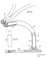
- Attached to the clamp piece in the center is a support tube directed under the seat and bent downwards, e.g. B. welded, which is supported on a pipe socket attached to a chair foot with the interposition of a plug pin or a height-adjustable gas spring.
- the seat height can be conveniently determined by choosing plug pins of different lengths.
- An axial thrust ball bearing is expediently arranged in the base-side pipe socket, on which the plug pin rests, so that the armchair can be rotated about a vertical axis.
- two armrests can also be assigned to the armchair, which consist of an arch piece which runs with its central section approximately parallel to the parallel metal frame sections and has a groove on the back with which the arch piece is pressed tightly onto the locking bar.
- the armrests are securely attached to the armchair by screwless connection.
- the invention achieves an armchair with a high utility value, which is characterized by a large number of advantages. On the one hand, it is largely transparent optically, so that it enables good integration into interior designs.
- the cushioning effect is achieved with a very small volume, e.g. B. with a network just one millimeter thick.
- the body contact surfaces of the armchair are permeable to heat flow and heat exchange between the body and its surroundings and for vapor diffusion (perspiration) to the atmosphere, which is particularly important for long periods of sitting when working, etc. is of great importance.
- the armchair offers a very high adaptation of the contact areas to the body with primary sitting posture and a largely automatic adjustment of the contact areas for secondary, changing sitting postures, such as those that change during work.
- the adaptation to the body is not brought about by material elasticity or material compression, but rather by a mesh material deformation without elongation, so that a flexible, changing adaptation is achieved with a consistently high support of the body contact surfaces.
- connection areas of the main armchair parts are invisible, but with a homogeneous load distribution. Due to the curved foot connection, only a minimal number of construction elements are required.
- the curved leg in conjunction with a flat plate foot plate provides a large free foot space.
- the overall structure of the armchair is characterized by good elasticity, which is achieved by an annular undulating of the footplate, by the curved foot design, by the cantilever of the seat frame surface, by the connection of the frame parts by means of an elastic closing strip and by a shape-adaptable mesh covering without elongation.
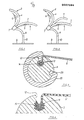
- the seat 1 and the backrest 2 each consist of a metal frame 3, 4 which are covered with a textile fabric 5, 6 and of an arcuate clamp piece 7 which holds the two metal frames 3 and 4 together.
- a support tube 8 directed under the seat 3 and bent downward is fastened in the center, for. B. welded, which is provided via a connector on a on a base plate 9 Pipe socket 10 is supported.
- the armchair according to FIG. 2 also has armrests 11, which consist of a single, curved piece which is fastened to the armchair with its central section in the region of the clamp piece 7.
- Figure 3 shows a section through the metal frame 3 of the seat.
- the metal frame 3 consists of extruded, hard aluminum rod material, which is bent into a closed ring.
- the frame is bent convex upwards on the sides of the chair and concave downwards in the longitudinal center of the chair at the front and back, so that the clamped flat structure forms a vaulted surface with two opposite curvatures.
- the aluminum frame 3 is provided with a longitudinal groove 12, the side walls of which are provided with undercuts 13 forming barbs.
- a soft aluminum wire 14 is tightly pressed into this groove 12 while enclosing the edge region of the textile fabric 5.
- FIG. 3 roughly illustrates the relationships that result when using a dense, woven cloth as a flexible sheet 5, which is pressed into the undercuts 13.
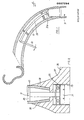
- Figure 5 shows an enlarged view of the rear node area of the chair, on which the backrest 2, armrest 11, seat 1 and support tube 8 are connected to each other.
- the metal frames 3, 4 have in their rear or lower region parallel longitudinal sections 16, 17 which run through the arcuate clamp piece 7, which has a cross section of approximately the shape "3" or “C".
- the sections 16, 17 are each closely and fittingly in the upper and lower semicircular receptacles 18, 19 of the "3" profile or “C” profile and are tightly clamped in the clamp piece 7 by an elastic closing strip 20 which is driven in between, whereby between the Strips 20 and the pipe sections 16, 17 interposed strips 21, 22 offer protection against shearing or other damage to the textile fabrics 5, 6.
- the armrest 11 has at its central area 23, which also runs parallel to the sections 16, 17, a groove 24 at the rear, with which the armrest 11 is pressed onto the edge of the wedge strip 20 protruding from the profile of the clamp 7.
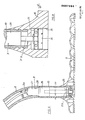
- FIG. 6 shows an enlarged view of the base plate 9 with a pipe socket 10 attached to it.
- the pipe socket there is an axial thrust ball bearing 25 at the bottom, on which sits a bolt 26 which is inserted into the pipe socket 10 and which engages in the support tube 8 with an upper, conical end 27. which has a conical receptacle 28 for the plug pin at its lower end.
- the metal frame 3 - and the metal frame 4 - are also provided with a further groove 29, which is at an angular distance of slightly more than 90 ° from the groove 12 below the seat.
- this groove 29 and in the groove 12 the ends of an overall approximately C-shaped cushion strip 30 are clamped, which optically covers the fastening point of the fabric 5 on the metal frame and the metal frame itself.
- the bolt 26 with the upper conical end 27 according to FIGS. 6 and 7 is the housing of a so-called called gas spring 31 with a valve tappet 31a projecting above, which can be depressed by means of an actuating double lever 32 articulated on the support tube 8 and a pressure transmission member 33 displaceably mounted in the support tube 8 for adjusting the seat height.
- the piston rod 31b of the gas spring 31 is supported on the rotary bearing 25.
- the thrust ball bearing 25 supporting the gas spring 31 is expediently seated on a screw 34 which is screwed into a threaded hole 35 in the bottom of the foot plate 36.
- This screw 34 thus allows a height adjustment of the gas spring 31 within the pipe socket 10 and thus the consideration of manufacturing tolerances in the area of the gap between the pipe socket 10 and the support tube 8.
- FIG. 9 shows an embodiment in which the plate 37 is cast with a conical receptacle 38, into which one is fitted with a corresponding conical one Bottom end 39 provided pipe socket 40 is pressed.
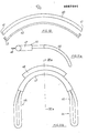
- FIG. 10 shows a plan view of the arcuate closing strip 20 used at the node point according to FIG. 5, which is provided with cutouts 41 on its ends on the convex side.
- the front edge 20 of the locking bar is covered by an arcuate strip 42 which is snapped onto the locking bar 20, its hooked ends 43 engaging in the recesses 41.
- Figure lla and b illustrate a modified embodiment of the armrests 44, 45.
- the two armrests each consisting of a wire bracket 46 to be foamed with plastic, are connected to one another via a pipe section 47 to which a locking bar 48 is directly welded.
- the armrest according to FIGS. 11a and 11b is used instead of the armrest 11 shown in FIG. 5 and the closing bar 20 shown there.
- FIG 12 shows a further embodiment for the base of the armchair.
- the foot plate 49 is here provided along its edge with a plurality of plastic sliding feet 50 which are inserted with a plug pin 59 into corresponding receiving holes in the foot plate 49.
- the base plate is again in the center with a conical
- FIG. 13 shows a plug pin 59 which can be used instead of the plug pin 55 according to FIG. 12 and instead of the pipe socket 53 there and represents the only connecting piece between the base plate 49 and the support tube 57.
- the plug pin 59 is fixed in a torsion-proof manner in the base plate and in the support tube, so that in such a case there is a rigid, non-rotating armchair.
- FIGS. 14 and 15 illustrate an embodiment of the connection point between support tube 60 and seat frame 61 and backrest frame 62, in which a solid node piece 63 is provided which has a conical receiving opening for the upper, somewhat tapered end 64 of the support tube 60.
- the knot piece 63 engages under the clamp piece 66 with a bow 65.
- the knot piece is first screwed to the lower bow 68 of the clamp piece by means of two screws 67, the screws increasing the strength of the metal frame 61 of the seat.
- a solid knot piece 72 is again provided, which encloses the lower half of the clamp piece 74 with an arc 73.
- the knot piece 72, the clamp piece 74 and the metal frame 70 of the seat are provided with successive through holes into which a stable pin 75 is pressed, which holds the knot piece on the clamp piece.
- the support tube 69 is in turn pressed with a conical end 76 into a conical opening of the node piece 72.
- a wedge-shaped cross pin 77 which has an inclined surface 78 on the clamp piece 74 the opposite side is supported on a ball or cylinder 79 clamped in the support tube, the support tube is held particularly tight and securely on the node piece.
Landscapes
- Chair Legs, Seat Parts, And Backrests (AREA)
- Chairs Characterized By Structure (AREA)
Abstract
Description
- Die Erfindung betrifft einen Sessel mit Sitz und Rückenlehne, von denen mindestens ein Teil aus einem flexiblen Flächengebilde besteht, das an einem Metallrahmen festgespannt ist, der mit einer Längsnut versehen ist, in welche ein längliches Metallteil unter Einfassung des Randes des Flächengebildes eingedrückt ist.
- In der Polstersesseltechnik werden heute meist Schaumstoffkörper auf harten Membranen oder gespannten Gurten oder Geweben aufgelegt. Diese Technik führt aber im allgemeinen zu voluminösen, schwergewichtigen Polstersesseln, die oft nur eine schlechte Unterstützung der Körperkontaktflächen bieten und bei denen ein Wärmestau an den Körperkontaktflächen auftritt.
- Ferner sind textilbespannte Sitzmöbel ohne Polsterauflage bekannt ( z. B. durch die FR-PS 1027 585, US-PS 3512 834 und GB-PS 2020 175 ), bei denen das Textilmaterial nur eben gespannt ist. Die Befestigung solcher flexibler Flächengebilde stellt bereits Schwierigkeiten dar, wenn die Metallrahmen im wesentlichen nur innerhalb einer Ebene liegen. Die sich dabei ergebenden Sesselformen haben jedoch nur ein sehr einfaches Erscheinungsbild und passen sich an die Körperauflage- und- berührungsflächen nicht an. Die Verankerung des Textilmaterials am Rahmen ist meist sichtbar, weshalb solche Sitzmöbel auch den ästhetischen Anforderungen wenig entsprechen. Darüber hinaus kommt es oft zu Überbeanspruchung des horizontal vorgespannten Textilmateriales.
- Komplexere und körperangepaßtere Sesselformen sind mit als dreidimensionale Raumkurven gebogenen Metallrahmen erreichbar, bei denen es jedoch Schwierigkeiten bereitet, das flexible Flächengebilde stabil zu verankern und gleichzeitig zu verspannen und die Sessel bzw. Rahmenteile miteinander zu verbinden.
- Der Erfindung liegt die Aufgabe zugrunde, einen gattungsgemäßen Sessel mit einem höchste Anpassung und Leichtigkeit ausstrahlenden Erscheinungsbild zu schaffen, wobei der Sessel eine mit einem soliden Gebrauchssessel vergleichbare Stabilität aufweisen soll. Darüber hinaus sollen die Körperkontaktflächen des Sessels wärmetechnisch und perspirationsmäßig durchlässig sein, eine optimale statische und dynamisch angepaßte Stützform aufweisen und sollen nur wenige, kleindimensionierte Konstruktionselemente zur Verbindung der Hauptsesselteile erforderlich sein.
- Zur Lösung dieser Aufgabe ist erfindungsgemäß vorgesehen, daß die Wände der Längsnut mit Widerhaken bildenden Hinterschneidungen versehen sind und daß das Metallteil aus Quetschmetall besteht, welches zusammen mit dem eingefaßten Rand des Flächengebildes bis in die Hinterschneidungen gepreßt ist. Der Metallrahmen besteht dabei vorzugsweise aus extrudiertem Stangenmaterial, oder Strangpreßprofilen, z. B. aus Hartaluminium. Als Quetschmetall wird vornehmlich ein weicher metallischer Draht, z. B. ein Weich-Aluminiumdraht verwendet. Das Flächengebilde kann gewebe- oder netzartig sein, wobei vorzugsweise ein netzartiges Flächengebilde aus geflochtenen, gewirkten oder gewebten, mono- oder multifilen Kunststofffäden verwendet wird.
- Wie umfangreiche Erprobungen ergeben haben, kann mit solchen metallischen Preß- und Quetschverbindungen eine überaus stabile Einspannung der Flächengebilde an dem Metallrahmen erreicht werden, wobei überraschenderweise das Flächengebilde im Bereich der Quetschverbindungen seine Stabilität voll beibehält. Dies zeigt sich insbesondere bei netzartigen Flächengebilden, durch deren Maschen hindurch das Quetschmetall bis in die Hinterschneidungen der rahmenseitigen Nut gedrückt wird, wonach die Netzfäden wie eine Armierung im Quetschmetall eingebettet und verankert sind.
- Gemäß einem weiteren Merkmal der Erfindung verlaufen die Nutwände winklig zum benachbarten Bereich des Flächengebildes. Vorzugsweise liegt die Nut an der dem Benutzer zugewandten Oberseite des Metallrahmens und ist eine weitere Nut am Metallrahmen in einem Winkelabstand von mehr als 90° unterhalb des Flächengebildes vorgesehen. In diesen beiden Nuten ist ein C-förmiger, den Rahmen außen umspannender Polsterstreifen befestigt. Durch einen solchen Polsterstreifen ist die Befestigungsstelle des flexiblen Flächengebildes optisch verdeckt.
- In weiterer Ausgestaltung der Erfindung kann vorgesehen werden, daß die Metallrahmen von Sitz und Rückenlehne - bezogen auf den Benutzer - auf den beiden Seiten des Sessels konvex und im vorderen und rückwärtigen Bereich konkav gekrümmt sind. Die Metallrahmen von Sitz und Rückenlehne liegen dabei gemäß einem weiteren Merkmal der Erfindung mit parallel zueinander verlaufenden Abschnitten in einem bogenförmigen im Querschnitt etwa C-förmigen Klammerstück, in welchem sie durch eine zwischen die Abschnitte eingeschobene bogenförmige Schließleiste eingespannt sind. Auf diese Weise wird eine schraublose, sehr unauffällig wirkende, jedoch äußerst stabile Verbindung von Sitz und Rückenlehne erreicht. An dem Klammerstück ist längsmittig ein unter den Sitz gerichtetes und nach unten hin abgebogenes Tragrohr befestigt, z. B. angeschweißt, welches sich auf einen an einem Sesselfuß angebrachten Rohrstutzen unter Zwischenschaltung eines Steckbolzens oder einer höhenverstellbaren Gasfeder abstützt. Durch Wahl unterschiedlich langer Steckbolzen kann somit bequem die Sitzhöhe bestimmt werden.
- In dem fußseitigen Rohrstutzen ist zweckmäßigerweise ein Axialdruck-Kugellager angeordnet, auf welchem der Steckbolzen aufsitzt, so daß der Sessel um eine vertikale Achse drehbar ist.
- Schließlich können der Erfindung zufolge dem Sessel noch zwei Armlehnen zugeordnet sein, welche aus einem Bogenstück bestehen, das mit seinem mittigen Abschnitt etwa parallel zu den parallelen Metallrahmenabschnitten verläuft und an der Rückseite eine Nut aufweist, mit welcher das Bogenstück auf die Schließleiste stramm aufgedrückt ist. Auf diese Weise sind auch die Armlehnen durch schraubenlose Verbindung stabil am Sessel befestigt.
- Weitere Merkmale und Abwandlungsmöglichkeiten des Sessels sind in der nachfolgenden Figurenbeschreibung und in den Unteransprüchen angegeben.
- Durch die Erfindung ist insgesamt ein Sessel hohen Gebrauchswertes erreicht, der sich durch eine Vielzahl von Vorteilen auszeichnet. Zum einen ist er optisch weitgehend transparent, so daß er eine gute Integration in Raumgestaltungen ermöglicht. Der Polsterungseffekt ist mit sehr geringem Volumen erreicht, z. B. mit einem nur einen Millimeter starkem Netz. Ferner sind die Körperkontaktflächen des Sessels für einen Wärmefluß und Wärmeaustausch zwischen Körper und Umgebung und für eine Dampfdiffusion ( Perspiration ) an die Atmosphäre durchlässig, was gerade für ein langes Sitzen beim Arbeiten u.s.w. von großer Bedeutung ist.
- Der Sessel bietet eine sehr hohe Anpassung der Kontaktflächen an den Körper bei primärer Sitzhaltung und eine weitestgehende, automatische Anpassung der Kontaktflächen für sekundäre, wechselnde Sitzhaltungen, wie diese sich beispielsweise bei Arbeiten ändern. Die Anpassung an den Körper wird hierbei nicht durch Materialelastizität bzw. Materialkompression bewirkt, sondern durch eine Netzmaterialverformung ohne Längendehnungen, so daß eine flexible, wechselnde Anpassung bei gleichbleibend hoher Abstützung der Körperkontaktflächen erreicht wird.
- Die Verbindungsbereiche der Hauptsesselteile sind unsichtbar, bei gleichzeitig aber homogener Lastverteilung. Durch die gekrümmte Fußanbindung werden nur eine minimale Anzahl von Konstruktionselementen benötigt. Durch das gekrümmte Bein wird in Verbindung mit einem flachen Plattenfußteller ein großer freier Fußraum erreicht.
- Ferner zeichnet sich die Gesamtkonstruktion des Sessels durch eine gute Elastizität aus, die erreicht ist durch eine ringförmige Ondulierung der Fußplatte, durch die gekrümmte Fußausbildung, durch Auskragung der Sitzrahmenfläche, durch die Verbindung der Rahmenteile mittels einer elastischen Schließleiste und durch eine formänderungsfähige Netzbespannung ohne Längendehnung.
- Die Erfindung wird im folgenden anhand der Zeichnung näher erläutert, in der zeigen :
- Figur 1 ein Ausführungsbeispiel eines Sessels nach der Erfindung,
- Figur 2 ein weiteres Ausführungsbeispiel, bei welchem der Sessel mit Armlehnen versehen ist,
- Figur 3 einen Schnitt durch den Rahmen von Sitz bzw. Rückenlehne.des Sessels nach den Figuren 1 oder 2,
- Figur 4 in vergrößerter Schnittdarstellung eine Skizze zur Veranschaulichung der Verankerung der Sesselbespannung am Metallrahmen,
- Figur 5 einen Vertikalschnitt durch die rückwärtige Verbindungsstelle von Rückenlehne, Armlehne, Sitz und Tragrohr des Sessels,
- Figur 6 einen Sesselfuß,
- Figur 7 eine Höhenverstelleinrichtung am Sesselfuß,
- Figur 8 und 9 je eine abgewandelte Ausführungsform eines Sesselfußes,
- Figur 10 zeigt eine zur Verkeilung von Sitz- und Rückenlehnenrahmen verwendete Schließleiste zusammen mit einem Abdeckstreifen,
- Figur 11 a und b veranschaulichen eine abgewandelte Ausführungsform der Armlehnen,
- Figur 12 zeigt eine abgewandelte Ausführungsform des Untergestelles des Sessels,
- Figur 13 zeigt einen Steckbolzen für eine starre, nichtdrehbare Ausführung des Untergestelles,
- Figur 14 zeigt im Vertikalschnitt eine abgewandelte Ausführungsform für die Verbindungsstelle von Sitz- und Rückenlehnenrahmen mit dem Tragrohr,
- Figur 15 zeigt einen Horizontalschnitt zur Ausführungsform na ch Figur 14,
- Figur 16 zeigt eine weitere abgewandelte Ausführungsform der Verbindungsstelle zwischen Sitzrahmen und Rückenlehnenrahmen einerseits und dem Tragrohr andrerseits und
- Figur 17 zeigt eine Draufsicht zu Figur 16.
- Bei den Sesseln nach den Figuren 1 und 2 bestehen der Sitz 1 und die Rückenlehne 2 jeweils aus einem Metallrahmen 3, 4, die mit einem textilen Flächengebilde 5, 6 bespannt sind und aus einem die beiden Metallrahmen 3 und 4 zusammenhaltenden, bogenförmigen Klammerstück 7. An dem im Querschnitt etwa C-förmigen Klammerstück 7 ist mittig ein unter den Sitz 3 gerichtetes und nach unten hin abgebogenes Tragrohr 8 befestigt, z. B. festgeschweißt, welches über eine Steckverbindung auf einem an einer Fußplatte 9 vorgesehenen Rohrstutzen 10 abgestützt ist. Der Sessel nach Figur 2 besitzt ferner Armlehnen 11, die aus einem einzigen, gebogenen Stück bestehen, das mit seinem mittleren Abschnitt im Bereich des Klammerstückes 7 am Sessel befestigt ist.
- Figur 3 zeigt einen Schnitt durch den Metallrahmen 3 des Sitzes. Der Metallrahmen 3 besteht aus extrudiertem, hartem Aluminiumstangenmaterial, welches zu einem geschlossenen Ring gebogen ist. Dabei ist der Rahmen an den Seiten des Sessels konvex nach oben und in der Längsmitte des Stuhles vorne und hinten konkav nach unten durchgebogen, so daß das eingespannte Flächengebilde eine zwei gegenläufige Krümmungen aufweisende Gewölbefläche bildet. An der Oberseite ist der Aluminium-Rahmen 3 mit einer Längsnut 12 versehen, deren Seitenwände mit Widerhaken bildenden Hinterschneidungen 13 versehen sind. In diese Nut 12 ist ein Weichaluminiumdraht 14 unter Einfassung des Randbereiches des textilen Flächengebildes 5 stramm eingedrückt. In Figur 3 sind in etwa die Verhältnisse veranschaulicht, die sich bei Verwendung eines dichten, gewebten Tuches als flexiblen Flächengebildes 5 ergeben, das in die Hinterschneidungen 13 hineingedrückt wird.
- Eine noch strammere Einspannung ergibt sich bei Verwendung eines Netzes 5'aus z. B. zerreißfesten Kunststoffäden als textiles Flächengebilde. Beim Einpressen dringt das Quetschmetall 15 durch die Maschen des Netzes 5'hindurch bis in die Hinterschneidungen 13 hinein, wonach der Randbereich des Netzes 5'in Quetschmetall 15 eingebettet ist und der vom Quetschmetall 15 gebildete Körper formschlüssig in den Hinterschneidungen 13 verankert ist. Am Rückenlehnenrahmen 4 ist das Flächengebilde 6 in der gleichen, anhand der Figur 3 und 4 beschriebenen Weise befestigt.
- Figur 5 zeigt in vergrößerter Darstellung den rückwärtigen Knotenbereich des Sessels, an welchem Rückenlehne 2, Armlehne 11, Sitz 1 und Tragrohr 8 miteinander verbunden sind. Die Metallrahmen 3, 4 weisen in ihrem hinteren, bzw. unteren Bereich parallele Längsabschnitte 16, 17 auf, die durch das bogenförmige Klammerstück 7 hindurch verlaufen, das einen Querschnitt von etwa der Form " 3 " oder " C " aufweist. Die Abschnitte 16, 17 liegen jeweils eng und passend in der oberen bzw. unteren halbrunden Aufnahme 18, 19 des " 3 " -Profiles bzw. "C"-Profils und sind durch eine dazwischengetriebeneelastische Schließleiste 20 stramm im Klammerstück 7 festgespannt, wobei zwischen der Schließleiste 20 und den Rohrabschnitten 16, 17 zwischengefügte Streifen 21, 22 Schutz gegen ein Abscheren oder eine sonstige Beschädigung der textilen Flächengebilde 5, 6 bieten.
- Die Armlehne 11 besitzt an ihrem mittleren, ebenfalls parallel zu den Abschnitten 16, 17 verlaufenden Bereich 23 rückwärtig eine Nut 24, mit der die Armlehne 11 auf den aus dem Profil der Klammer 7 herausragenden Rand der Keilleiste 20 aufgepreßt ist.
- Figur 6 zeigt in vergrößerter Darstellung die Fußplatte 9 mit daran befestigtem Rohrstutzen 10. In dem Rohrstutzen liegt unten ein Axialdruckkugellager 25, auf dem ein in dem Rohrstutzen 10 eingesteckter Bolzen 26 sitzt, der mit einem oberen, kegeligen Ende 27 in das Tragrohr 8 greift, welches an seinem unteren Ende eine konische Aufnahme 28 für den Steckbolzen besitzt.
- Wie aus Figur 3 ferner noch ersichtlich ist, ist der Metallrahmen 3 - und der Metallrahmen 4 - noch mit einer weiteren Nut 29 versehen, die in einem Winkelabstand von etwas mehr als 90° von der Nut 12 entfernt unterhalb des Sitzes liegt. In diese Nut 29 und in die Nut 12 sind die Enden eines insgesamt etwa C-förmigen Polsterstreifens 30 eingeklemmt, welcher die Befestigungsstelle des Flächengebildes 5 am Metallrahmen und den Metallrahmen selbst optisch abdeckt.
- Bei dem Bolzen 26 mit oberem konischen Ende 27 nach den Figuren 6 und 7 handelt es sich um das Gehäuse einer sogenannten Gasfeder 31 mit einem oben vorstehenden Ventilstößel 31a, welcher mittels eines am Tragrohr 8 angelenkten Betätigungs-Doppelhebels 32 und eines im Tragrohr 8 verschieblich gelagerten Druckübertragungsgliedes 33 zur Sitzhöhenverstellung niedergedrückt werden kann. Die Kolbenstange 31b der Gasfeder 31 stützt sich auf dem Drehlager 25 ab.
- Wie aus Figur 8 ersichtlich ist, sitzt das die Gasfeder 31 abstützende Axialdruckkugellager 25 zweckmäßigerweise auf einer Schraube 34 auf, die in ein bodenseitiges Gewindeloch 35 der Fußplatte 36 eingeschraubt ist. Diese Schraube 34 erlaubt somit eine Höhenverstellung der Gasfeder 31 innerhalb des Rohrstutzens 10 und somit die Berücksichtigung von Fertigungstoleranzen im Bereich des Spaltes zwischen Rohrstutzen 10 und Tragrohr 8.
- Während bei den Ausführungsbeispielen nach den Figuren 6 und 8 die Fußplatte 9 bzw. 36 unmittelbar an den Rohrstutzen 10 angegossen ist, zeigt Figur 9 eine Ausführungsform, bei welcher der Teller 37 mit einer konischen Aufnahme 38 gegossen ist, in die ein mit einem entsprechenden kegeligen Fußende 39 versehener Rohrstutzen 40 eingedrückt ist.
- Figur 10 zeigt eine Draufsicht auf die an der Knotenstelle nach Figur 5 verwendete bogenförmige Schließleiste 20, die an ihren Enden auf der konvexen Seite mit Aussparungen 41 versehen ist. Bei Sesseln, die keine Armlehnen 11 aufweisen ( vergleiche Figur 1 ), wird die Schließleiste 20 an ihrem vorderen Rand mittels eines bogenförmigen Streifens 42 abgedeckt, der federnd auf die Schließleiste 20 aufgeschnappt wird, wobei seine hakenförmigen Enden 43 in die Aussparungen 41 eingreifen.
- Figur lla und b veranschaulichen eine abgewandelte Ausführungsform der Armlehnen 44, 45. Die beiden Armlehnen, die jeweils aus einem mit Kunststoff zu umschäumenden Drahtbügel 46 bestehen, sind über ein Rohrstück 47 miteinander verbunden, an welches eine Schließleiste 48 unmittelbar angeschweißt ist. Die Armlehne nach den Figuren lla und llb wird anstelle der in Figur 5 gezeigten Armlehne 11 und der dort gezeigten Schließleiste 20 verwendet.
- Figur 12 zeigt eine weitere Ausführungsform für das Untergestell des Sessels. Die Fußplatte 49 ist hier längs ihres Randes mit mehreren Gleitfüßen 50 aus Kunststoff versehen, die mit einem Steckzapfen 59 in entsprechende Aufnahmelöcher der Fußplatte 49 gesteckt sind. Die Fußplatte ist wiederum in ihrem Zentrum mit einer konischen
- Öffnung 52 versehen, in die das untere, kegelig sich verjüngende Ende eines Rohrstutzens 53 eingesteckt ist. In dem Rohrstutzen ist wiederum ein Axialkugellager 54 angeordnet, auf dem ein Steckbolzen 55 aufsitzt, der drehbar im Rohrstutzen 53 gelagert ist. Zur Erhöhung der Gleitfähigkeit ist der Rohrstutzen 53 mit einer den mittleren, zylinderischen Abschnitt des Steckbolzens 55 umschließenden Gleithülse 56 ausgekleidet. Auf das obere kegelige bzw. kegelstumpfförmige Ende des Steckbolzens 55 ist das gebogene Tragrohr 57 aufgesteckt, das an das Klammerstück 7 angeschweißt ist, wobei noch eine Verst ärkungsplatte 58 zwischen Klammerstück 7 und der Unterseite des Tragrohres vorgesehen ist. Bei der Ausführungsform nach Figur 12 liegt ein massiver Steckbolzen 55 vor, so daß eine Höhenverstellung des Sitzes hier nicht möglich ist.
- Figur 13 zeigt einen Steckbolzen 59, der anstelle des Steckbolzens 55 nach Figur 12 und anstelle des dortigen Rohrstutzens 53 verwendbar ist und das einzige Verbindungsstück zwischen Fußplatte 49 und dem Tragrohr 57 darstellt. Der Steckbolzen 59 setzt sich verdrehungsfest in der Fußplatte und im Tragrohr fest, so daß in einem solchen Falle ein starrer, nicht drehbarer Sessel vorliegt..
- Die Figuren 14 und 15 veranschaulichen eine Ausführungsform der Verbindungsstelle zwischen Tragrohr 60 und Sitzrahmen 61 und Rückenlehnenrahmen 62, bei der ein massives Knotenstück 63 vorgesehen ist, das eine konische Aufnahmeöffnung für das obere, sich etwas kegelig verjüngende Ende 64 des Tragrohres 60 aufweist. Das Knotenstück 63 untergreift mit einem Bogen 65 das Klammerstück 66. Bevor das Tragrohr 60 in das Knotenstück 63 eingesteckt wird, ist zunächst das Knotenstück mittels zwei Schrauben 67 an dem unteren Bogen 68 des Klammerstückes festgeschraubt, wobei die Schrauben zur Erhöhung der Festigkeit den Metallrahmen 61 des Sitzes durchdringen.
- Bei der in den Figuren 16 und 17 gezeigten abgewandelten Ausführungsform der Verbindungsstelle zwischen Tragrohr 69 und den Metallrahmen 70, 71 von Sitz und Rückenlehne ist wiederum ein massives Knotenstück 72 vorgesehen, das mit einem Bogen 73 die untere Hälfte des Klammerstückes 74 umschließt. Das Knotenstück 72, das Klammerstück 74 und der Metallrahmen 70 des Sitzes sind mit hintereinanderliegenden Durchgangslöchern versehen, in welche ein stabiler Stift 75 eingepreßt ist, der das Knotenstück am Klammerstück hält. Das Tragrohr 69 ist wiederum mit einem kegeligen Ende 76 in eine koni-sche Öffnung des Knotenstückes 72 eingedrückt. Durch einen keilförmigen Querstift 77, der sich mit einer Schrägfläche 78 auf der dem Klammerstück 74 abgewandten Seite an einer im Tragrohr festgeklemmten Kugel oder Zylinder 79 abstützt, ist das Tragrohr besonders stramm und sicher am Knotenstück gehalten.
Claims (16)
Applications Claiming Priority (2)
| Application Number | Priority Date | Filing Date | Title |
|---|---|---|---|
| DE19823207352 DE3207352A1 (de) | 1982-03-02 | 1982-03-02 | Sessel |
| DE3207352 | 1982-03-02 |
Publications (3)
| Publication Number | Publication Date |
|---|---|
| EP0087594A2 true EP0087594A2 (de) | 1983-09-07 |
| EP0087594A3 EP0087594A3 (en) | 1984-11-28 |
| EP0087594B1 EP0087594B1 (de) | 1986-12-30 |
Family
ID=6157038
Family Applications (1)
| Application Number | Title | Priority Date | Filing Date |
|---|---|---|---|
| EP83100849A Expired EP0087594B1 (de) | 1982-03-02 | 1983-01-29 | Sessel |
Country Status (4)
| Country | Link |
|---|---|
| US (1) | US4552406A (de) |
| EP (1) | EP0087594B1 (de) |
| CA (1) | CA1212305A (de) |
| DE (2) | DE3207352A1 (de) |
Cited By (2)
| Publication number | Priority date | Publication date | Assignee | Title |
|---|---|---|---|---|
| EP0702946A1 (de) * | 1994-09-13 | 1996-03-27 | Ortopedia Gmbh | Rollstuhl mit Verkleidungsteilen |
| WO2009153556A1 (en) * | 2008-06-17 | 2009-12-23 | Thomas Oliver Duncan Higgs | A chair |
Families Citing this family (27)
| Publication number | Priority date | Publication date | Assignee | Title |
|---|---|---|---|---|
| KR100334316B1 (ko) | 1992-06-15 | 2002-10-11 | 헤르만밀러인코퍼레이티드 | 사무용의자의지지장치및제조방법 |
| DE19544210A1 (de) * | 1995-11-28 | 1997-06-05 | Stoll Sedus Ag | Sitzmöbel mit zwei seitlichen Profilschienen |
| US6053558A (en) * | 1997-10-01 | 2000-04-25 | Penda Corporation | Cover assembly for the cargo area of a vehicle |
| USD463144S1 (en) | 2000-09-28 | 2002-09-24 | Formway Furniture Limited | Chair |
| USD460300S1 (en) | 2000-09-28 | 2002-07-16 | Formway Furniture Limited | Slotted seat panel for a chair |
| USD445580S1 (en) | 2000-09-28 | 2001-07-31 | Formway Furniture Limited | Chair |
| USD448277S1 (en) | 2000-09-28 | 2001-09-25 | Formway Furniture Limited | Castor |
| USD446397S1 (en) | 2000-09-28 | 2001-08-14 | Formway Furniture Limited | Chair |
| USD448219S1 (en) | 2000-09-28 | 2001-09-25 | Formway Furniture Limited | Castored base for a chair |
| AU783829B2 (en) | 2000-09-28 | 2005-12-08 | Formway Furniture Limited | A reclinable chair |
| AUPR054400A0 (en) | 2000-09-29 | 2000-10-26 | Formway Furniture Limited | A castor |
| DE10048779A1 (de) * | 2000-09-29 | 2002-04-18 | Stoll Sedus Ag | Rückenlehne |
| NZ518944A (en) | 2002-05-14 | 2004-09-24 | Formway Furniture Ltd | Height adjustable arm for chair with outer stem releasably lockable to inner stem by engagement of recesses |
| ITVI20020148A1 (it) * | 2002-07-05 | 2004-01-05 | Nardi Spa | Dispositivo di bloccaggio di un elemento laminare flassibile ad un telaio |
| US20050194829A1 (en) * | 2004-03-08 | 2005-09-08 | Chad Aerts | Fabric attachment device |
| PT1858372E (pt) * | 2005-03-01 | 2013-06-03 | Haworth Inc | Encosto de cadeira |
| GB0511393D0 (en) * | 2005-06-04 | 2005-07-13 | Space Net Technology Ltd | A seating system |
| GB2426698A (en) * | 2005-06-04 | 2006-12-06 | Space Net Technology Ltd | Push-chair with two closed support frames over which a flexible membrane is stretched |
| US7395590B2 (en) * | 2005-06-10 | 2008-07-08 | Haworth, Inc. | Method for assembling a frame assembly for a chair |
| US7461442B2 (en) * | 2005-06-10 | 2008-12-09 | Haworth, Inc. | Assembly apparatus and process for a chair back |
| TWI360400B (en) * | 2008-06-24 | 2012-03-21 | Teng Hsu Yang | Chair and chair covering |
| US8662560B2 (en) | 2009-07-27 | 2014-03-04 | Lear Corporation | Vehicle seating attachment assembly |
| USD705561S1 (en) | 2013-05-16 | 2014-05-27 | Steelcase Inc. | Chair |
| USD708466S1 (en) | 2013-05-16 | 2014-07-08 | Steelcase Inc. | Chair |
| USD704945S1 (en) | 2013-05-16 | 2014-05-20 | Steelcase Inc. | Chair |
| US10118704B2 (en) | 2015-04-10 | 2018-11-06 | Franklin Products, Inc. | Hybrid seat pan and diaphragm |
| JP5967740B1 (ja) * | 2015-07-30 | 2016-08-10 | 株式会社リディアワークス | シートの展張装置 |
Family Cites Families (9)
| Publication number | Priority date | Publication date | Assignee | Title |
|---|---|---|---|---|
| US1553862A (en) * | 1923-05-03 | 1925-09-15 | Kirsch Charles Wendel | Shade-fastening means for window-shade rollers |
| FR1027585A (fr) * | 1950-11-13 | 1953-05-13 | Perfectionnements aux sièges métalliques pliants | |
| US3041109A (en) * | 1958-09-29 | 1962-06-26 | Miller Herman Inc | Web and spreader furniture construction |
| US3143165A (en) * | 1961-07-18 | 1964-08-04 | Ted W Lewis | Metal frame structure and preformed structural units comprising the same |
| US3425028A (en) * | 1966-06-17 | 1969-01-28 | Burndy Corp | Clamp connector |
| US3512834A (en) * | 1967-12-22 | 1970-05-19 | Shott Chairs Corp | Method and means for securing the ends of the webbing material to the frame of garden or porch furniture |
| US3604752A (en) * | 1969-09-16 | 1971-09-14 | United States Steel Corp | Support member for a vehicle seat |
| US3891270A (en) * | 1974-05-10 | 1975-06-24 | Krueger Metal Products | Pneumatic stool with foot rest connected to seat base |
| IT1094427B (it) * | 1978-04-18 | 1985-08-02 | Internatinal System Developmen | Intelaiatura di sedia,poltroncina e similari,provvista di mezzi atti al fissaggio amovibile di un materiale di copertura di una imbottitura |
-
1982
- 1982-03-02 DE DE19823207352 patent/DE3207352A1/de not_active Withdrawn
-
1983
- 1983-01-18 US US06/458,925 patent/US4552406A/en not_active Expired - Fee Related
- 1983-01-29 DE DE8383100849T patent/DE3368502D1/de not_active Expired
- 1983-01-29 EP EP83100849A patent/EP0087594B1/de not_active Expired
- 1983-03-01 CA CA000422626A patent/CA1212305A/en not_active Expired
Cited By (3)
| Publication number | Priority date | Publication date | Assignee | Title |
|---|---|---|---|---|
| EP0702946A1 (de) * | 1994-09-13 | 1996-03-27 | Ortopedia Gmbh | Rollstuhl mit Verkleidungsteilen |
| WO2009153556A1 (en) * | 2008-06-17 | 2009-12-23 | Thomas Oliver Duncan Higgs | A chair |
| US8657374B2 (en) | 2008-06-17 | 2014-02-25 | Thomas Oliver Duncan Higgs | Chair |
Also Published As
| Publication number | Publication date |
|---|---|
| EP0087594B1 (de) | 1986-12-30 |
| DE3368502D1 (en) | 1987-02-05 |
| DE3207352A1 (de) | 1983-09-08 |
| US4552406A (en) | 1985-11-12 |
| EP0087594A3 (en) | 1984-11-28 |
| CA1212305A (en) | 1986-10-07 |
Similar Documents
| Publication | Publication Date | Title |
|---|---|---|
| EP0087594B1 (de) | Sessel | |
| EP1039816B1 (de) | Stuhlmechanik | |
| EP0949875B1 (de) | Rahmenkonstruktion, stellmechanik und polsterbezug für einen stuhl | |
| DE69326241T3 (de) | Bürostuhl | |
| EP0885576A3 (de) | Sitzmöbel, insbesondere Bürodrehstuhl | |
| EP0114034A1 (de) | Sitzmöbel | |
| EP1911374A1 (de) | Personensitz mit ergonomischen Lahnenteil | |
| EP3295829B1 (de) | Stuhl, insbesondere konferenz- oder bürostuhl, verfahren zur herstellung eines stuhls | |
| EP1201162A2 (de) | Sitzmöbel aus schichtweise verleimtem Formsperrholz | |
| EP0910264A1 (de) | Rahmen für liege- oder sitzmöbel | |
| EP1850698A2 (de) | Sessel | |
| DE202004011233U1 (de) | Unterfederung für Auflagen von Sitz- oder Liegemöbeln | |
| DE3313677C2 (de) | Sitzmöbel, insbesondere Bürostuhl mit synchron verstellbarer Rückenlehne und Sitzfläche | |
| DE3742465C2 (de) | ||
| EP0951226A2 (de) | Sitzmöbel | |
| DE202007013776U1 (de) | Polstermöbelstück | |
| DE69620345T2 (de) | Stuhl, welcher an die Körperform des Benutzers anpassbar ist | |
| EP4342334B1 (de) | Rückenlehne für einen stuhl sowie stuhl | |
| DE2262594C3 (de) | Polstersitz o.dgl | |
| DE69507834T2 (de) | Federstruktur für möbel und dergleichen | |
| WO2018114515A9 (de) | Stuhl, vorzugsweise drehstuhl | |
| WO2024012812A1 (de) | Unterfederungselement für eine matratze, unterfederung und ein unterfederungssystem | |
| DE2421970A1 (de) | Sitz- bzw. liegemoebel | |
| WO2023083411A1 (de) | Modulares klappbettsystem, installationsanordnung und klappbettmodul hierfür | |
| CH718248A1 (de) | Stützanordnung für einen Stuhl. |
Legal Events
| Date | Code | Title | Description |
|---|---|---|---|
| PUAI | Public reference made under article 153(3) epc to a published international application that has entered the european phase |
Free format text: ORIGINAL CODE: 0009012 |
|
| AK | Designated contracting states |
Designated state(s): DE FR GB IT NL |
|
| PUAL | Search report despatched |
Free format text: ORIGINAL CODE: 0009013 |
|
| AK | Designated contracting states |
Designated state(s): DE FR GB IT NL |
|
| 17P | Request for examination filed |
Effective date: 19841017 |
|
| GRAA | (expected) grant |
Free format text: ORIGINAL CODE: 0009210 |
|
| AK | Designated contracting states |
Kind code of ref document: B1 Designated state(s): DE FR GB IT NL |
|
| REF | Corresponds to: |
Ref document number: 3368502 Country of ref document: DE Date of ref document: 19870205 |
|
| ITF | It: translation for a ep patent filed | ||
| ET | Fr: translation filed | ||
| PLBE | No opposition filed within time limit |
Free format text: ORIGINAL CODE: 0009261 |
|
| STAA | Information on the status of an ep patent application or granted ep patent |
Free format text: STATUS: NO OPPOSITION FILED WITHIN TIME LIMIT |
|
| 26N | No opposition filed | ||
| ITTA | It: last paid annual fee | ||
| REG | Reference to a national code |
Ref country code: FR Ref legal event code: ST |
|
| PGFP | Annual fee paid to national office [announced via postgrant information from national office to epo] |
Ref country code: DE Payment date: 19931209 Year of fee payment: 12 |
|
| PGFP | Annual fee paid to national office [announced via postgrant information from national office to epo] |
Ref country code: FR Payment date: 19931223 Year of fee payment: 12 |
|
| PGFP | Annual fee paid to national office [announced via postgrant information from national office to epo] |
Ref country code: GB Payment date: 19940120 Year of fee payment: 12 |
|
| PGFP | Annual fee paid to national office [announced via postgrant information from national office to epo] |
Ref country code: NL Payment date: 19940131 Year of fee payment: 12 |
|
| PG25 | Lapsed in a contracting state [announced via postgrant information from national office to epo] |
Ref country code: GB Effective date: 19950129 |
|
| PG25 | Lapsed in a contracting state [announced via postgrant information from national office to epo] |
Ref country code: NL Effective date: 19950801 |
|
| GBPC | Gb: european patent ceased through non-payment of renewal fee |
Effective date: 19950129 |
|
| PG25 | Lapsed in a contracting state [announced via postgrant information from national office to epo] |
Ref country code: FR Effective date: 19950929 |
|
| NLV4 | Nl: lapsed or anulled due to non-payment of the annual fee |
Effective date: 19950801 |
|
| PG25 | Lapsed in a contracting state [announced via postgrant information from national office to epo] |
Ref country code: DE Effective date: 19951003 |
|
| REG | Reference to a national code |
Ref country code: FR Ref legal event code: ST |