EP0087594A2 - Chaise - Google Patents
Chaise Download PDFInfo
- Publication number
- EP0087594A2 EP0087594A2 EP83100849A EP83100849A EP0087594A2 EP 0087594 A2 EP0087594 A2 EP 0087594A2 EP 83100849 A EP83100849 A EP 83100849A EP 83100849 A EP83100849 A EP 83100849A EP 0087594 A2 EP0087594 A2 EP 0087594A2
- Authority
- EP
- European Patent Office
- Prior art keywords
- armchair
- armchair according
- seat
- metal
- metal frame
- Prior art date
- Legal status (The legal status is an assumption and is not a legal conclusion. Google has not performed a legal analysis and makes no representation as to the accuracy of the status listed.)
- Granted
Links
Images


Classifications
-
- A—HUMAN NECESSITIES
- A47—FURNITURE; DOMESTIC ARTICLES OR APPLIANCES; COFFEE MILLS; SPICE MILLS; SUCTION CLEANERS IN GENERAL
- A47C—CHAIRS; SOFAS; BEDS
- A47C21/00—Attachments for beds, e.g. sheet holders or bed-cover holders; Ventilating, cooling or heating means in connection with bedsteads or mattresses
- A47C21/02—Holders for loose bed elements, e.g. sheet holders; bed cover holders
- A47C21/022—Sheet holders; Bed cover holders
-
- A—HUMAN NECESSITIES
- A47—FURNITURE; DOMESTIC ARTICLES OR APPLIANCES; COFFEE MILLS; SPICE MILLS; SUCTION CLEANERS IN GENERAL
- A47C—CHAIRS; SOFAS; BEDS
- A47C5/00—Chairs of special materials
- A47C5/04—Metal chairs, e.g. tubular
-
- A—HUMAN NECESSITIES
- A47—FURNITURE; DOMESTIC ARTICLES OR APPLIANCES; COFFEE MILLS; SPICE MILLS; SUCTION CLEANERS IN GENERAL
- A47C—CHAIRS; SOFAS; BEDS
- A47C5/00—Chairs of special materials
- A47C5/04—Metal chairs, e.g. tubular
- A47C5/06—Special adaptation of seat upholstery or fabric for attachment to tubular chairs
-
- Y—GENERAL TAGGING OF NEW TECHNOLOGICAL DEVELOPMENTS; GENERAL TAGGING OF CROSS-SECTIONAL TECHNOLOGIES SPANNING OVER SEVERAL SECTIONS OF THE IPC; TECHNICAL SUBJECTS COVERED BY FORMER USPC CROSS-REFERENCE ART COLLECTIONS [XRACs] AND DIGESTS
- Y10—TECHNICAL SUBJECTS COVERED BY FORMER USPC
- Y10T—TECHNICAL SUBJECTS COVERED BY FORMER US CLASSIFICATION
- Y10T403/00—Joints and connections
- Y10T403/71—Rod side to plate or side
- Y10T403/7129—Laterally spaced rods
- Y10T403/7141—Plural channels in connector
-
- Y—GENERAL TAGGING OF NEW TECHNOLOGICAL DEVELOPMENTS; GENERAL TAGGING OF CROSS-SECTIONAL TECHNOLOGIES SPANNING OVER SEVERAL SECTIONS OF THE IPC; TECHNICAL SUBJECTS COVERED BY FORMER USPC CROSS-REFERENCE ART COLLECTIONS [XRACs] AND DIGESTS
- Y10—TECHNICAL SUBJECTS COVERED BY FORMER USPC
- Y10T—TECHNICAL SUBJECTS COVERED BY FORMER US CLASSIFICATION
- Y10T403/00—Joints and connections
- Y10T403/71—Rod side to plate or side
- Y10T403/7171—Two rods encompassed by single connector
Definitions
- the invention relates to an armchair with a seat and backrest, at least part of which consists of a flexible flat structure which is clamped to a metal frame which is provided with a longitudinal groove, into which an elongated metal part is pressed while enclosing the edge of the flat structure.
- textile-covered seating furniture without upholstery is known (e.g. from FR-PS 1027 585, US-PS 3512 834 and GB-PS 2020 175), in which the textile material only is just excited.
- the attachment of such flexible fabrics already presents difficulties if the metal frames are essentially only within one plane.
- the resulting armchair shapes have only a very simple appearance and do not adapt to the body support and contact surfaces.
- the anchoring of the textile material on the frame is usually visible, which is why such seating furniture does not meet the aesthetic requirements.
- the horizontally prestressed textile material is often overstressed.
- More complex and body-fitting armchair shapes can be achieved with metal frames that are curved as three-dimensional spatial curves, but with which it is difficult to anchor the flexible flat structure in a stable manner and at the same time to brace it and to connect the armchairs or frame parts to one another.
- the invention has for its object to provide a generic armchair with the highest adaptation and lightness radiating appearance, the armchair should have a stability comparable to a solid armchair.
- the body contact surfaces of the armchair should be permeable to heat and perspiration, an optimal one have static and dynamically adapted support form and should only require a few, small-sized construction elements for connecting the main armchair parts.
- the walls of the longitudinal groove are provided with barbs forming undercuts and that the metal part consists of crushed metal, which is pressed together with the bordered edge of the fabric up to the undercuts.
- the metal frame is preferably made of extruded rod material, or extruded profiles, for. B. made of hard aluminum.
- a soft metallic wire e.g. B. uses a soft aluminum wire.
- the flat structure can be fabric-like or mesh-like, preferably a mesh-like fabric made of braided, knitted or woven, mono- or multifilament plastic threads being used.
- the groove walls run at an angle to the adjacent area of the fabric.
- the groove preferably lies on the upper side of the metal frame facing the user and a further groove is provided on the metal frame at an angular distance of more than 90 ° below the fabric.
- a C-shaped cushion strip is fastened, which spans the outside of the frame.
- the attachment point of the flexible fabric is optically covered by such a cushion strip.
- the metal frame of the seat and backrest - with respect to the user - are convexly curved on both sides of the armchair and concave in the front and rear area.
- the metal frames of the seat and backrest lie with sections running parallel to one another in an arcuate clip piece which is approximately C-shaped in cross section and in which they are clamped by an arcuate closing strip inserted between the sections. That way achieved a screwless, very unobtrusive, but extremely stable connection between seat and backrest.
- Attached to the clamp piece in the center is a support tube directed under the seat and bent downwards, e.g. B. welded, which is supported on a pipe socket attached to a chair foot with the interposition of a plug pin or a height-adjustable gas spring.
- the seat height can be conveniently determined by choosing plug pins of different lengths.
- An axial thrust ball bearing is expediently arranged in the base-side pipe socket, on which the plug pin rests, so that the armchair can be rotated about a vertical axis.
- two armrests can also be assigned to the armchair, which consist of an arch piece which runs with its central section approximately parallel to the parallel metal frame sections and has a groove on the back with which the arch piece is pressed tightly onto the locking bar.
- the armrests are securely attached to the armchair by screwless connection.
- the invention achieves an armchair with a high utility value, which is characterized by a large number of advantages. On the one hand, it is largely transparent optically, so that it enables good integration into interior designs.
- the cushioning effect is achieved with a very small volume, e.g. B. with a network just one millimeter thick.
- the body contact surfaces of the armchair are permeable to heat flow and heat exchange between the body and its surroundings and for vapor diffusion (perspiration) to the atmosphere, which is particularly important for long periods of sitting when working, etc. is of great importance.
- the armchair offers a very high adaptation of the contact areas to the body with primary sitting posture and a largely automatic adjustment of the contact areas for secondary, changing sitting postures, such as those that change during work.
- the adaptation to the body is not brought about by material elasticity or material compression, but rather by a mesh material deformation without elongation, so that a flexible, changing adaptation is achieved with a consistently high support of the body contact surfaces.
- connection areas of the main armchair parts are invisible, but with a homogeneous load distribution. Due to the curved foot connection, only a minimal number of construction elements are required.
- the curved leg in conjunction with a flat plate foot plate provides a large free foot space.
- the overall structure of the armchair is characterized by good elasticity, which is achieved by an annular undulating of the footplate, by the curved foot design, by the cantilever of the seat frame surface, by the connection of the frame parts by means of an elastic closing strip and by a shape-adaptable mesh covering without elongation.
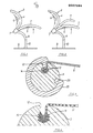
- the seat 1 and the backrest 2 each consist of a metal frame 3, 4 which are covered with a textile fabric 5, 6 and of an arcuate clamp piece 7 which holds the two metal frames 3 and 4 together.
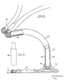
- a support tube 8 directed under the seat 3 and bent downward is fastened in the center, for. B. welded, which is provided via a connector on a on a base plate 9 Pipe socket 10 is supported.
- the armchair according to FIG. 2 also has armrests 11, which consist of a single, curved piece which is fastened to the armchair with its central section in the region of the clamp piece 7.
- Figure 3 shows a section through the metal frame 3 of the seat.
- the metal frame 3 consists of extruded, hard aluminum rod material, which is bent into a closed ring.
- the frame is bent convex upwards on the sides of the chair and concave downwards in the longitudinal center of the chair at the front and back, so that the clamped flat structure forms a vaulted surface with two opposite curvatures.
- the aluminum frame 3 is provided with a longitudinal groove 12, the side walls of which are provided with undercuts 13 forming barbs.
- a soft aluminum wire 14 is tightly pressed into this groove 12 while enclosing the edge region of the textile fabric 5.
- FIG. 3 roughly illustrates the relationships that result when using a dense, woven cloth as a flexible sheet 5, which is pressed into the undercuts 13.
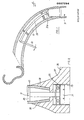
- Figure 5 shows an enlarged view of the rear node area of the chair, on which the backrest 2, armrest 11, seat 1 and support tube 8 are connected to each other.
- the metal frames 3, 4 have in their rear or lower region parallel longitudinal sections 16, 17 which run through the arcuate clamp piece 7, which has a cross section of approximately the shape "3" or “C".
- the sections 16, 17 are each closely and fittingly in the upper and lower semicircular receptacles 18, 19 of the "3" profile or “C” profile and are tightly clamped in the clamp piece 7 by an elastic closing strip 20 which is driven in between, whereby between the Strips 20 and the pipe sections 16, 17 interposed strips 21, 22 offer protection against shearing or other damage to the textile fabrics 5, 6.
- the armrest 11 has at its central area 23, which also runs parallel to the sections 16, 17, a groove 24 at the rear, with which the armrest 11 is pressed onto the edge of the wedge strip 20 protruding from the profile of the clamp 7.
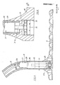
- FIG. 6 shows an enlarged view of the base plate 9 with a pipe socket 10 attached to it.
- the pipe socket there is an axial thrust ball bearing 25 at the bottom, on which sits a bolt 26 which is inserted into the pipe socket 10 and which engages in the support tube 8 with an upper, conical end 27. which has a conical receptacle 28 for the plug pin at its lower end.
- the metal frame 3 - and the metal frame 4 - are also provided with a further groove 29, which is at an angular distance of slightly more than 90 ° from the groove 12 below the seat.
- this groove 29 and in the groove 12 the ends of an overall approximately C-shaped cushion strip 30 are clamped, which optically covers the fastening point of the fabric 5 on the metal frame and the metal frame itself.
- the bolt 26 with the upper conical end 27 according to FIGS. 6 and 7 is the housing of a so-called called gas spring 31 with a valve tappet 31a projecting above, which can be depressed by means of an actuating double lever 32 articulated on the support tube 8 and a pressure transmission member 33 displaceably mounted in the support tube 8 for adjusting the seat height.
- the piston rod 31b of the gas spring 31 is supported on the rotary bearing 25.
- the thrust ball bearing 25 supporting the gas spring 31 is expediently seated on a screw 34 which is screwed into a threaded hole 35 in the bottom of the foot plate 36.
- This screw 34 thus allows a height adjustment of the gas spring 31 within the pipe socket 10 and thus the consideration of manufacturing tolerances in the area of the gap between the pipe socket 10 and the support tube 8.
- FIG. 9 shows an embodiment in which the plate 37 is cast with a conical receptacle 38, into which one is fitted with a corresponding conical one Bottom end 39 provided pipe socket 40 is pressed.
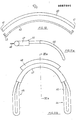
- FIG. 10 shows a plan view of the arcuate closing strip 20 used at the node point according to FIG. 5, which is provided with cutouts 41 on its ends on the convex side.
- the front edge 20 of the locking bar is covered by an arcuate strip 42 which is snapped onto the locking bar 20, its hooked ends 43 engaging in the recesses 41.
- Figure lla and b illustrate a modified embodiment of the armrests 44, 45.
- the two armrests each consisting of a wire bracket 46 to be foamed with plastic, are connected to one another via a pipe section 47 to which a locking bar 48 is directly welded.
- the armrest according to FIGS. 11a and 11b is used instead of the armrest 11 shown in FIG. 5 and the closing bar 20 shown there.
- FIG 12 shows a further embodiment for the base of the armchair.
- the foot plate 49 is here provided along its edge with a plurality of plastic sliding feet 50 which are inserted with a plug pin 59 into corresponding receiving holes in the foot plate 49.
- the base plate is again in the center with a conical
- FIG. 13 shows a plug pin 59 which can be used instead of the plug pin 55 according to FIG. 12 and instead of the pipe socket 53 there and represents the only connecting piece between the base plate 49 and the support tube 57.
- the plug pin 59 is fixed in a torsion-proof manner in the base plate and in the support tube, so that in such a case there is a rigid, non-rotating armchair.
- FIGS. 14 and 15 illustrate an embodiment of the connection point between support tube 60 and seat frame 61 and backrest frame 62, in which a solid node piece 63 is provided which has a conical receiving opening for the upper, somewhat tapered end 64 of the support tube 60.
- the knot piece 63 engages under the clamp piece 66 with a bow 65.
- the knot piece is first screwed to the lower bow 68 of the clamp piece by means of two screws 67, the screws increasing the strength of the metal frame 61 of the seat.
- a solid knot piece 72 is again provided, which encloses the lower half of the clamp piece 74 with an arc 73.
- the knot piece 72, the clamp piece 74 and the metal frame 70 of the seat are provided with successive through holes into which a stable pin 75 is pressed, which holds the knot piece on the clamp piece.
- the support tube 69 is in turn pressed with a conical end 76 into a conical opening of the node piece 72.
- a wedge-shaped cross pin 77 which has an inclined surface 78 on the clamp piece 74 the opposite side is supported on a ball or cylinder 79 clamped in the support tube, the support tube is held particularly tight and securely on the node piece.
Landscapes
- Chair Legs, Seat Parts, And Backrests (AREA)
- Chairs Characterized By Structure (AREA)
Applications Claiming Priority (2)
| Application Number | Priority Date | Filing Date | Title |
|---|---|---|---|
| DE19823207352 DE3207352A1 (de) | 1982-03-02 | 1982-03-02 | Sessel |
| DE3207352 | 1982-03-02 |
Publications (3)
| Publication Number | Publication Date |
|---|---|
| EP0087594A2 true EP0087594A2 (fr) | 1983-09-07 |
| EP0087594A3 EP0087594A3 (en) | 1984-11-28 |
| EP0087594B1 EP0087594B1 (fr) | 1986-12-30 |
Family
ID=6157038
Family Applications (1)
| Application Number | Title | Priority Date | Filing Date |
|---|---|---|---|
| EP83100849A Expired EP0087594B1 (fr) | 1982-03-02 | 1983-01-29 | Chaise |
Country Status (4)
| Country | Link |
|---|---|
| US (1) | US4552406A (fr) |
| EP (1) | EP0087594B1 (fr) |
| CA (1) | CA1212305A (fr) |
| DE (2) | DE3207352A1 (fr) |
Cited By (2)
| Publication number | Priority date | Publication date | Assignee | Title |
|---|---|---|---|---|
| EP0702946A1 (fr) * | 1994-09-13 | 1996-03-27 | Ortopedia Gmbh | Chaise roulante avec parties d'habillage |
| WO2009153556A1 (fr) * | 2008-06-17 | 2009-12-23 | Thomas Oliver Duncan Higgs | Chaise |
Families Citing this family (27)
| Publication number | Priority date | Publication date | Assignee | Title |
|---|---|---|---|---|
| KR100334316B1 (ko) | 1992-06-15 | 2002-10-11 | 헤르만밀러인코퍼레이티드 | 사무용의자의지지장치및제조방법 |
| DE19544210A1 (de) * | 1995-11-28 | 1997-06-05 | Stoll Sedus Ag | Sitzmöbel mit zwei seitlichen Profilschienen |
| US6053558A (en) * | 1997-10-01 | 2000-04-25 | Penda Corporation | Cover assembly for the cargo area of a vehicle |
| USD463144S1 (en) | 2000-09-28 | 2002-09-24 | Formway Furniture Limited | Chair |
| USD460300S1 (en) | 2000-09-28 | 2002-07-16 | Formway Furniture Limited | Slotted seat panel for a chair |
| USD445580S1 (en) | 2000-09-28 | 2001-07-31 | Formway Furniture Limited | Chair |
| USD448277S1 (en) | 2000-09-28 | 2001-09-25 | Formway Furniture Limited | Castor |
| USD446397S1 (en) | 2000-09-28 | 2001-08-14 | Formway Furniture Limited | Chair |
| USD448219S1 (en) | 2000-09-28 | 2001-09-25 | Formway Furniture Limited | Castored base for a chair |
| AU783829B2 (en) | 2000-09-28 | 2005-12-08 | Formway Furniture Limited | A reclinable chair |
| AUPR054400A0 (en) | 2000-09-29 | 2000-10-26 | Formway Furniture Limited | A castor |
| DE10048779A1 (de) * | 2000-09-29 | 2002-04-18 | Stoll Sedus Ag | Rückenlehne |
| NZ518944A (en) | 2002-05-14 | 2004-09-24 | Formway Furniture Ltd | Height adjustable arm for chair with outer stem releasably lockable to inner stem by engagement of recesses |
| ITVI20020148A1 (it) * | 2002-07-05 | 2004-01-05 | Nardi Spa | Dispositivo di bloccaggio di un elemento laminare flassibile ad un telaio |
| US20050194829A1 (en) * | 2004-03-08 | 2005-09-08 | Chad Aerts | Fabric attachment device |
| PT1858372E (pt) * | 2005-03-01 | 2013-06-03 | Haworth Inc | Encosto de cadeira |
| GB0511393D0 (en) * | 2005-06-04 | 2005-07-13 | Space Net Technology Ltd | A seating system |
| GB2426698A (en) * | 2005-06-04 | 2006-12-06 | Space Net Technology Ltd | Push-chair with two closed support frames over which a flexible membrane is stretched |
| US7395590B2 (en) * | 2005-06-10 | 2008-07-08 | Haworth, Inc. | Method for assembling a frame assembly for a chair |
| US7461442B2 (en) * | 2005-06-10 | 2008-12-09 | Haworth, Inc. | Assembly apparatus and process for a chair back |
| TWI360400B (en) * | 2008-06-24 | 2012-03-21 | Teng Hsu Yang | Chair and chair covering |
| US8662560B2 (en) | 2009-07-27 | 2014-03-04 | Lear Corporation | Vehicle seating attachment assembly |
| USD705561S1 (en) | 2013-05-16 | 2014-05-27 | Steelcase Inc. | Chair |
| USD708466S1 (en) | 2013-05-16 | 2014-07-08 | Steelcase Inc. | Chair |
| USD704945S1 (en) | 2013-05-16 | 2014-05-20 | Steelcase Inc. | Chair |
| US10118704B2 (en) | 2015-04-10 | 2018-11-06 | Franklin Products, Inc. | Hybrid seat pan and diaphragm |
| JP5967740B1 (ja) * | 2015-07-30 | 2016-08-10 | 株式会社リディアワークス | シートの展張装置 |
Family Cites Families (9)
| Publication number | Priority date | Publication date | Assignee | Title |
|---|---|---|---|---|
| US1553862A (en) * | 1923-05-03 | 1925-09-15 | Kirsch Charles Wendel | Shade-fastening means for window-shade rollers |
| FR1027585A (fr) * | 1950-11-13 | 1953-05-13 | Perfectionnements aux sièges métalliques pliants | |
| US3041109A (en) * | 1958-09-29 | 1962-06-26 | Miller Herman Inc | Web and spreader furniture construction |
| US3143165A (en) * | 1961-07-18 | 1964-08-04 | Ted W Lewis | Metal frame structure and preformed structural units comprising the same |
| US3425028A (en) * | 1966-06-17 | 1969-01-28 | Burndy Corp | Clamp connector |
| US3512834A (en) * | 1967-12-22 | 1970-05-19 | Shott Chairs Corp | Method and means for securing the ends of the webbing material to the frame of garden or porch furniture |
| US3604752A (en) * | 1969-09-16 | 1971-09-14 | United States Steel Corp | Support member for a vehicle seat |
| US3891270A (en) * | 1974-05-10 | 1975-06-24 | Krueger Metal Products | Pneumatic stool with foot rest connected to seat base |
| IT1094427B (it) * | 1978-04-18 | 1985-08-02 | Internatinal System Developmen | Intelaiatura di sedia,poltroncina e similari,provvista di mezzi atti al fissaggio amovibile di un materiale di copertura di una imbottitura |
-
1982
- 1982-03-02 DE DE19823207352 patent/DE3207352A1/de not_active Withdrawn
-
1983
- 1983-01-18 US US06/458,925 patent/US4552406A/en not_active Expired - Fee Related
- 1983-01-29 DE DE8383100849T patent/DE3368502D1/de not_active Expired
- 1983-01-29 EP EP83100849A patent/EP0087594B1/fr not_active Expired
- 1983-03-01 CA CA000422626A patent/CA1212305A/fr not_active Expired
Cited By (3)
| Publication number | Priority date | Publication date | Assignee | Title |
|---|---|---|---|---|
| EP0702946A1 (fr) * | 1994-09-13 | 1996-03-27 | Ortopedia Gmbh | Chaise roulante avec parties d'habillage |
| WO2009153556A1 (fr) * | 2008-06-17 | 2009-12-23 | Thomas Oliver Duncan Higgs | Chaise |
| US8657374B2 (en) | 2008-06-17 | 2014-02-25 | Thomas Oliver Duncan Higgs | Chair |
Also Published As
| Publication number | Publication date |
|---|---|
| EP0087594B1 (fr) | 1986-12-30 |
| DE3368502D1 (en) | 1987-02-05 |
| DE3207352A1 (de) | 1983-09-08 |
| US4552406A (en) | 1985-11-12 |
| EP0087594A3 (en) | 1984-11-28 |
| CA1212305A (fr) | 1986-10-07 |
Similar Documents
| Publication | Publication Date | Title |
|---|---|---|
| EP0087594B1 (fr) | Chaise | |
| EP1039816B1 (fr) | Mecanique de fauteuil | |
| EP0949875B1 (fr) | Cadre, mecanisme de reglage et revetement rembourre pour un siege | |
| DE69326241T3 (de) | Bürostuhl | |
| EP0885576A3 (fr) | Meuble d'assise, notamment chaise de bureau | |
| EP0114034A1 (fr) | Siège | |
| EP1911374A1 (fr) | Siège avec dossier ergonomique | |
| EP3295829B1 (fr) | Chaise, en particulier chaise de bureau ou de conférence, procédé de fabrication d'une chaise | |
| EP1201162A2 (fr) | Siège en matière contre-plaqué collé | |
| EP0910264A1 (fr) | Cadre con u pour un siege ou pour un lit | |
| EP1850698A2 (fr) | Fauteuil | |
| DE202004011233U1 (de) | Unterfederung für Auflagen von Sitz- oder Liegemöbeln | |
| DE3313677C2 (de) | Sitzmöbel, insbesondere Bürostuhl mit synchron verstellbarer Rückenlehne und Sitzfläche | |
| DE3742465C2 (fr) | ||
| EP0951226A2 (fr) | Siege | |
| DE202007013776U1 (de) | Polstermöbelstück | |
| DE69620345T2 (de) | Stuhl, welcher an die Körperform des Benutzers anpassbar ist | |
| EP4342334B1 (fr) | Dossier pour chaise et chaise | |
| DE2262594C3 (de) | Polstersitz o.dgl | |
| DE69507834T2 (de) | Federstruktur für möbel und dergleichen | |
| WO2018114515A9 (fr) | Chaise, de préférence chaise pivotante | |
| WO2024012812A1 (fr) | Élément de ressort de support pour matelas, agencement de ressort de support et système de ressort de support | |
| DE2421970A1 (de) | Sitz- bzw. liegemoebel | |
| WO2023083411A1 (fr) | Système de lit pliant modulaire, ensemble d'installation et module de lit pliant pour celui-ci | |
| CH718248A1 (de) | Stützanordnung für einen Stuhl. |
Legal Events
| Date | Code | Title | Description |
|---|---|---|---|
| PUAI | Public reference made under article 153(3) epc to a published international application that has entered the european phase |
Free format text: ORIGINAL CODE: 0009012 |
|
| AK | Designated contracting states |
Designated state(s): DE FR GB IT NL |
|
| PUAL | Search report despatched |
Free format text: ORIGINAL CODE: 0009013 |
|
| AK | Designated contracting states |
Designated state(s): DE FR GB IT NL |
|
| 17P | Request for examination filed |
Effective date: 19841017 |
|
| GRAA | (expected) grant |
Free format text: ORIGINAL CODE: 0009210 |
|
| AK | Designated contracting states |
Kind code of ref document: B1 Designated state(s): DE FR GB IT NL |
|
| REF | Corresponds to: |
Ref document number: 3368502 Country of ref document: DE Date of ref document: 19870205 |
|
| ITF | It: translation for a ep patent filed | ||
| ET | Fr: translation filed | ||
| PLBE | No opposition filed within time limit |
Free format text: ORIGINAL CODE: 0009261 |
|
| STAA | Information on the status of an ep patent application or granted ep patent |
Free format text: STATUS: NO OPPOSITION FILED WITHIN TIME LIMIT |
|
| 26N | No opposition filed | ||
| ITTA | It: last paid annual fee | ||
| REG | Reference to a national code |
Ref country code: FR Ref legal event code: ST |
|
| PGFP | Annual fee paid to national office [announced via postgrant information from national office to epo] |
Ref country code: DE Payment date: 19931209 Year of fee payment: 12 |
|
| PGFP | Annual fee paid to national office [announced via postgrant information from national office to epo] |
Ref country code: FR Payment date: 19931223 Year of fee payment: 12 |
|
| PGFP | Annual fee paid to national office [announced via postgrant information from national office to epo] |
Ref country code: GB Payment date: 19940120 Year of fee payment: 12 |
|
| PGFP | Annual fee paid to national office [announced via postgrant information from national office to epo] |
Ref country code: NL Payment date: 19940131 Year of fee payment: 12 |
|
| PG25 | Lapsed in a contracting state [announced via postgrant information from national office to epo] |
Ref country code: GB Effective date: 19950129 |
|
| PG25 | Lapsed in a contracting state [announced via postgrant information from national office to epo] |
Ref country code: NL Effective date: 19950801 |
|
| GBPC | Gb: european patent ceased through non-payment of renewal fee |
Effective date: 19950129 |
|
| PG25 | Lapsed in a contracting state [announced via postgrant information from national office to epo] |
Ref country code: FR Effective date: 19950929 |
|
| NLV4 | Nl: lapsed or anulled due to non-payment of the annual fee |
Effective date: 19950801 |
|
| PG25 | Lapsed in a contracting state [announced via postgrant information from national office to epo] |
Ref country code: DE Effective date: 19951003 |
|
| REG | Reference to a national code |
Ref country code: FR Ref legal event code: ST |