EP0087600A2 - Echangeur de chaleur pour pompe à chaleur - Google Patents
Echangeur de chaleur pour pompe à chaleur Download PDFInfo
- Publication number
- EP0087600A2 EP0087600A2 EP83100900A EP83100900A EP0087600A2 EP 0087600 A2 EP0087600 A2 EP 0087600A2 EP 83100900 A EP83100900 A EP 83100900A EP 83100900 A EP83100900 A EP 83100900A EP 0087600 A2 EP0087600 A2 EP 0087600A2
- Authority
- EP
- European Patent Office
- Prior art keywords
- heat exchanger
- parts
- vault
- exchanger according
- coils
- Prior art date
- Legal status (The legal status is an assumption and is not a legal conclusion. Google has not performed a legal analysis and makes no representation as to the accuracy of the status listed.)
- Granted
Links
- 229910052500 inorganic mineral Inorganic materials 0.000 claims abstract description 5
- 239000011707 mineral Substances 0.000 claims abstract description 5
- 239000000654 additive Substances 0.000 claims abstract description 4
- 239000012267 brine Substances 0.000 claims description 13
- HPALAKNZSZLMCH-UHFFFAOYSA-M sodium;chloride;hydrate Chemical compound O.[Na+].[Cl-] HPALAKNZSZLMCH-UHFFFAOYSA-M 0.000 claims description 13
- 239000003507 refrigerant Substances 0.000 claims description 5
- 239000003795 chemical substances by application Substances 0.000 claims description 3
- 238000010438 heat treatment Methods 0.000 claims description 3
- 239000007787 solid Substances 0.000 claims description 3
- XLYOFNOQVPJJNP-UHFFFAOYSA-N water Substances O XLYOFNOQVPJJNP-UHFFFAOYSA-N 0.000 claims description 3
- 239000000835 fiber Substances 0.000 claims description 2
- 239000002184 metal Substances 0.000 claims description 2
- 239000010438 granite Substances 0.000 abstract description 2
- 238000005338 heat storage Methods 0.000 abstract description 2
- 239000003570 air Substances 0.000 description 10
- 238000010521 absorption reaction Methods 0.000 description 5
- 210000001503 joint Anatomy 0.000 description 5
- 230000000694 effects Effects 0.000 description 2
- 239000002360 explosive Substances 0.000 description 2
- 238000002347 injection Methods 0.000 description 2
- 239000007924 injection Substances 0.000 description 2
- 239000012080 ambient air Substances 0.000 description 1
- 238000010276 construction Methods 0.000 description 1
- 239000000975 dye Substances 0.000 description 1
- -1 e.g. Basalt Substances 0.000 description 1
- 238000001704 evaporation Methods 0.000 description 1
- 230000008020 evaporation Effects 0.000 description 1
- 238000000605 extraction Methods 0.000 description 1
- 230000002349 favourable effect Effects 0.000 description 1
- 230000005484 gravity Effects 0.000 description 1
- 239000007788 liquid Substances 0.000 description 1
- 238000004519 manufacturing process Methods 0.000 description 1
- 238000000034 method Methods 0.000 description 1
- 230000005855 radiation Effects 0.000 description 1
- 229910000679 solder Inorganic materials 0.000 description 1
- 230000000087 stabilizing effect Effects 0.000 description 1
Images
Classifications
-
- F—MECHANICAL ENGINEERING; LIGHTING; HEATING; WEAPONS; BLASTING
- F24—HEATING; RANGES; VENTILATING
- F24S—SOLAR HEAT COLLECTORS; SOLAR HEAT SYSTEMS
- F24S10/00—Solar heat collectors using working fluids
- F24S10/50—Solar heat collectors using working fluids the working fluids being conveyed between plates
- F24S10/502—Solar heat collectors using working fluids the working fluids being conveyed between plates having conduits formed by paired plates and internal partition means
-
- Y—GENERAL TAGGING OF NEW TECHNOLOGICAL DEVELOPMENTS; GENERAL TAGGING OF CROSS-SECTIONAL TECHNOLOGIES SPANNING OVER SEVERAL SECTIONS OF THE IPC; TECHNICAL SUBJECTS COVERED BY FORMER USPC CROSS-REFERENCE ART COLLECTIONS [XRACs] AND DIGESTS
- Y02—TECHNOLOGIES OR APPLICATIONS FOR MITIGATION OR ADAPTATION AGAINST CLIMATE CHANGE
- Y02B—CLIMATE CHANGE MITIGATION TECHNOLOGIES RELATED TO BUILDINGS, e.g. HOUSING, HOUSE APPLIANCES OR RELATED END-USER APPLICATIONS
- Y02B10/00—Integration of renewable energy sources in buildings
- Y02B10/20—Solar thermal
-
- Y—GENERAL TAGGING OF NEW TECHNOLOGICAL DEVELOPMENTS; GENERAL TAGGING OF CROSS-SECTIONAL TECHNOLOGIES SPANNING OVER SEVERAL SECTIONS OF THE IPC; TECHNICAL SUBJECTS COVERED BY FORMER USPC CROSS-REFERENCE ART COLLECTIONS [XRACs] AND DIGESTS
- Y02—TECHNOLOGIES OR APPLICATIONS FOR MITIGATION OR ADAPTATION AGAINST CLIMATE CHANGE
- Y02E—REDUCTION OF GREENHOUSE GAS [GHG] EMISSIONS, RELATED TO ENERGY GENERATION, TRANSMISSION OR DISTRIBUTION
- Y02E10/00—Energy generation through renewable energy sources
- Y02E10/40—Solar thermal energy, e.g. solar towers
- Y02E10/44—Heat exchange systems
Definitions
- the invention relates to a heat exchanger, in particular for heat pumps or for direct hot water heating in summer, preferably from setting sprayable and / or pourable mineral components reinforced with metal or fiber mats, in which pipe coils are embedded.
- the invention has for its object to provide a heat exchanger which has an optimal degree of heat absorption and is simple and inexpensive to manufacture.
- This object is achieved in that the heat exchanger is vaulted or kink-roofed, the coils being arranged in the walls.
- two symmetrical half parts put together result in a vault.
- the coils required for heat exchange are cast into the walls of these two symmetrical half parts.
- the vault tunnel formed in this way which can be extended as desired by stringing together several such half-part pairs, can absorb heat from the ambient air or solar radiation on its outside.
- the inner surface of the vaulted tunnel can be controlled by adjustable mechanical means e.g. Any amount of air can be applied to fans and baffles. As a result of different outside temperatures, it is possible to offer only the amount of heat that the compressor of the heat pump can withstand in the characteristic curve that is permissible for it, without being damaged.
- the parts forming a vault tunnel can preferably be held together and centered in the vertical vault closure plane by means of a round tube, angled tube, double-T profile, solid bar or tongue and groove arrangement.
- the number of parts is practically arbitrary, the parts can be arranged symmetrically and not symmetrically to each other.
- the two symmetrical half parts assembled into a vault form a vertical vault closure plane in the middle.
- Centering means such as a round tube, an angled tube, a double-T profile, a solid rod or a tongue and groove arrangement, are attached in the middle of this vault closure level.
- these stabilizing and possibly centering agents have the task of processing thermal expansions without damage, on the other hand they correspond statically due to the weight of the parts, furthermore due to the position of the center of gravity of the individual parts, through additional non-positive connections and due to the characteristics of the vaulted construction, the usual loads, such as Wind pressure, snow load etc.
- the parts are preferably attached to strips and / or to anchors in the area of their base levels.
- the radial butt joints of the vaulted ones widen Half parts to the inside of the vault.
- the joints of the half-parts are designed so that they wedge-like towards the inside of the vault or downwards and thus counteract the explosive effect of the ice by diverting the ice wedge that forms to the inside.
- the outwardly facing surfaces of the half parts have radial ribs or shafts and / or the inwardly facing surfaces of the half parts have axial ribs or shafts.
- the outward-facing surfaces of the vaulted tunnel may therefore have radial ribs or waves.
- the internal vaulted surfaces may contain axial ribs or shafts to enlarge the exchange surfaces.
- the parts are shaped such that in the assembled state they form a vaulted tunnel with an angular or curved cross-section, the angle of inclination of 80% of the entire outer surface being at least 100 in the case of an angular cross-section and the tangent angle of at least 10 over at least in the case of curved outer surfaces Is 80% of the total center of curvature.
- the vault formed by the parts can have an angular, curved or circular cross-section.
- the inclination of the irradiable surfaces is chosen so that an inclination angle of at least 10 ° is maintained for flat surfaces and the tangents to these outer surfaces for at least 80% of these outer surfaces also result in at least 10 0 for curved surfaces.
- the outward-facing surfaces of the parts are preferably coated with agents containing dark dyes.
- Another means of increasing heat absorption is to apply dark layers to the outer surfaces of the vault.
- the sprayable and / or pourable mineral components preferably contain additives to increase the coefficient of thermal conductivity.
- additives such as e.g. Basalt, granite etc. added.
- the vault-like parts are designed as double shells provided with air channels, in the outer walls and in the inner walls of which coils are arranged, the air channels and the inner surface of the vault tunnel having axial ribs and waves and the outer surfaces having radial ribs and waves.
- a double shell is used to enlarge the exchange surface system used, which by doubling the coils and integrating air ducts between the coils while simultaneously ribbing the air duct system significantly improves the possibility of heat extraction.
- the tubes containing a refrigerant preferably work in the form of an evaporator, the refrigerant preferably being injected into the tube ends near the vault closing level and the suction taking place in the vicinity of the base level.
- the multiple injection system is used, the liquid refrigerant being injected into the pipe ends of the coils of the same length in the area of the vault closing level and the evaporation preferably taking place from top to bottom to the pipe end in the area of the foot level goes.
- the cross-sections and pipe lengths as well as the lengths of the injection and suction connection lines are always the same; in connection with the associated solder fittings and nozzles, the same pressure losses are always guaranteed.
- the connection is made via leads of equal length to the collecting point of the compressor suction line.
- the pipe coils containing a brine work as a brine heat exchanger, in which all the pipe coils having the same pipe resistance are connected in parallel to one another via two collecting pipes, the collecting pipe for the cold brine preferably in the area of the base level and the collecting pipe for the heated one preferably brine is arranged in the area of the vault closure level.
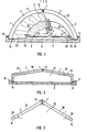
- the heat exchanger according to the invention is shown in perspective view in FIG. It consists of the two half parts 1 and 2. In the walls 3 and 4 of the half parts 1 and 2, the coils 5 are arranged.
- the two symmetrical half parts 1 and 2 are composed in such a way that a vaulted tunnel 6 results.
- the two half parts 1 and 2 touch in a vertical vault closing plane 7.
- An angled tube ') o is used as the centering means in the middle of the vault closing plane 7.
- This angled tube 10 serves to statically fix the arched half parts.
- strips 16 and 17 are arranged on their base levels 14 and 15. These strips 16 and 17 or similar anchors are attached to the substructure 8, for example a foundation or a roof structure.
- the be from the two halves 1 and 2 standing vaults can be extended as often as desired by stringing together several half-parts to form a vault. In Figure 1, this is done by the two half parts 1 'and 2 1 .
- the resulting radial butt joints 18 and 19 are wedge-shaped to the vault interior 2o to counteract the explosive effect when ice forms.
- the outwardly facing surfaces 21 and 22 have radial ribs or waves (not shown in FIG. 1) to enlarge the surface.
- the inwardly facing surfaces 23 and 24 of the vault 6, on the other hand, are provided with axial ribs or shafts, also not shown in FIG.
- fans with baffles for intensive air guidance and sound absorption are also accommodated in the arch tunnel 6, also not shown in FIG. 1.
- the coils 5 and 5 ' are preferably supplied by means of the connections 25.
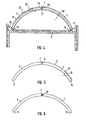
- FIGS. 2 to 6 Different embodiments of vaults are shown in FIGS. 2 to 6.
- the vaults are composed of two symmetrical half parts 1 and 2.
- the centering in the vault closing plane 7 can be done in various ways, namely by means of a full rod 12 of a double-T-profile 11, a groove 49 - and spring 5 0 arrangement 13, a circular tube 9 or a rectangular rod 48.
- Variously can also the cross-sections of the vaults.
- vaults with angular cross sections 27 and 26 are shown.
- the vaults have a curved cross section 28.
- the inclination of the irradiable surfaces 3o is chosen so that an angle of inclination 29 of at least 10 ° is maintained, namely over at least 80% of the total outside surface of the vault.
- the curvature is designed such that the tangent angle 32 over the entire center line of curvature 33 is likewise at least 10 ° at at least 80%.
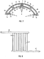
- a heat exchanger is shown as a double shell system.
- the two symmetrical half parts 1 and 2 here consist of two double shells 35 and 36.
- the outer walls 37 and 38 of the double shells 35 and 36 contain coils 41.
- the inner walls 39 and 4o of the double shells 35 and 36 also contain coils 42.
- the outer walls 37 and 38 and the inner walls 39 and 4o are separated by air channels 34.
- the inner surface 43 and the air channels 34 contain axial ribs or shafts, not shown in FIG. 7.
- the outer surfaces 44 are designed with radial ribs or waves.
- connecting pipe ends 45 of the coils 41 and 42 of the same length are preferably led out side by side in such a way that connection work can be carried out easily.
- Mechanical means e.g. Fans cause the air to pass through e.g. by fan action.
- FIG. 8 shows a preferred connection system for process water and brine heating of the coils 5.
- the collecting line 46 leads the brine via the coils 5 connected in parallel to one another into another collecting line 47.
- the lines all have the same pipe resistance.
- the connection of the collecting line 46 for the cold brine is preferably carried out in the area of the base levels 14 and 15, while the heated brine is preferably connected in the area of the vault closing level 7 by means of the collecting line 47.
Landscapes
- Engineering & Computer Science (AREA)
- Physics & Mathematics (AREA)
- Life Sciences & Earth Sciences (AREA)
- Sustainable Development (AREA)
- Sustainable Energy (AREA)
- Thermal Sciences (AREA)
- Chemical & Material Sciences (AREA)
- Combustion & Propulsion (AREA)
- Mechanical Engineering (AREA)
- General Engineering & Computer Science (AREA)
- Heat-Exchange Devices With Radiators And Conduit Assemblies (AREA)
- Compression-Type Refrigeration Machines With Reversible Cycles (AREA)
Priority Applications (1)
| Application Number | Priority Date | Filing Date | Title |
|---|---|---|---|
| AT83100900T ATE20277T1 (de) | 1982-02-25 | 1983-02-01 | Waermetauscher fuer waermepumpen. |
Applications Claiming Priority (2)
| Application Number | Priority Date | Filing Date | Title |
|---|---|---|---|
| DE3206701 | 1982-02-25 | ||
| DE3206701A DE3206701C2 (de) | 1982-02-25 | 1982-02-25 | Wärmetauscher für Wärmepumpen oder für die direkte Erwärmung von Brauchwasser |
Publications (3)
| Publication Number | Publication Date |
|---|---|
| EP0087600A2 true EP0087600A2 (fr) | 1983-09-07 |
| EP0087600A3 EP0087600A3 (en) | 1984-05-16 |
| EP0087600B1 EP0087600B1 (fr) | 1986-06-04 |
Family
ID=6156622
Family Applications (1)
| Application Number | Title | Priority Date | Filing Date |
|---|---|---|---|
| EP83100900A Expired EP0087600B1 (fr) | 1982-02-25 | 1983-02-01 | Echangeur de chaleur pour pompe à chaleur |
Country Status (3)
| Country | Link |
|---|---|
| EP (1) | EP0087600B1 (fr) |
| AT (1) | ATE20277T1 (fr) |
| DE (2) | DE3206701C2 (fr) |
Families Citing this family (3)
| Publication number | Priority date | Publication date | Assignee | Title |
|---|---|---|---|---|
| DE3404376A1 (de) * | 1984-02-08 | 1985-08-14 | M.A.N. Maschinenfabrik Augsburg-Nürnberg AG, 8500 Nürnberg | Waermeaustauschelemente des "luftroehrentyps" |
| DE3700315A1 (de) * | 1987-01-05 | 1988-07-14 | Strobach Elektromeister Gmbh | Grossflaechenwaermetauscher |
| DE4442578A1 (de) * | 1994-11-30 | 1996-06-05 | Winkelmann Gmbh & Co Kg Ziegel | Wärmedämmfassade für Solarenergiegewinnung |
Family Cites Families (21)
| Publication number | Priority date | Publication date | Assignee | Title |
|---|---|---|---|---|
| ES247631A1 (es) * | 1959-02-13 | 1959-06-01 | Amat Bargues Miguel | Sistema para el aprovechamiento de la energia contenida en los rayos solares |
| US3369539A (en) * | 1965-10-22 | 1968-02-20 | Harry E. Thomason | Solar heat trap |
| DE2527414A1 (de) * | 1975-06-20 | 1976-12-30 | Geb Oehrig Edith Boening | Konvexdach als sonnenheizung zur dachung von gebaeuden, haeusern und hohlkoerpern |
| GB1555485A (en) * | 1976-06-08 | 1979-11-14 | Dobson M J W D | Heat exchangers and method of manufacture same |
| DE7621510U1 (de) * | 1976-07-07 | 1977-01-13 | Schmidt, Heinz-Dieter, 5227 Windeck | Dachplatte |
| US4164933A (en) * | 1976-10-06 | 1979-08-21 | Alosi Anthony C | Concrete solar collectors |
| ES455830A1 (es) * | 1977-02-11 | 1978-01-01 | Trimboli Longetto A Adriano | Disposicion para la captacion de la energia solar aplicable a la aclimatacion de todo tipo de edificios. |
| CH632035A5 (en) * | 1977-05-09 | 1982-09-15 | Toos Etablissement | Roof or wall covering, in particular for the heat insulation of house walls or roofs |
| FR2395469A1 (fr) * | 1977-06-24 | 1979-01-19 | Parica Cie Paris Ingenieurs Co | Capteur de chaleur solaire |
| US4146014A (en) * | 1977-06-24 | 1979-03-27 | Joseph Allegro | Inner roof solar system |
| DE2733172A1 (de) * | 1977-07-22 | 1979-02-01 | Progress Consult Untersuchunge | Vorrichtung zur waermegewinnung |
| US4222373A (en) * | 1977-07-26 | 1980-09-16 | Davis Michael A | Ceramic solar collector |
| DE2814004A1 (de) * | 1978-03-31 | 1979-10-11 | Woermann Bauchemie Holding Ag | Bauwerk mit einer betonplatte und betonplatte |
| DE2819642A1 (de) * | 1978-05-05 | 1979-11-08 | Ludowigs Kg Fa Richard | Klimaanlage fuer wohnhaeuser |
| DE2826937A1 (de) * | 1978-06-20 | 1980-01-03 | Heliotherm Ag | Flachkollektor zur erwaermung fluessiger medien |
| GB2026679B (en) * | 1978-07-24 | 1983-02-09 | Solar Holding Sa | Solar energy collector and system |
| US4300539A (en) * | 1978-09-22 | 1981-11-17 | Ecosol Materials, Inc. | Solar collector |
| FR2454074A1 (fr) * | 1979-04-10 | 1980-11-07 | Comte Paul | Dispositifs echangeurs de chaleur a plaques tubulaires munies de canaux paralleles |
| DE2940838A1 (de) * | 1979-10-09 | 1981-04-23 | Heinz Dipl.-Ing. 3501 Zierenberg Borsdorf | Mineralischer flaechenabsorberkollektor |
| DE3000289A1 (de) * | 1980-01-05 | 1981-07-09 | Peter 4224 Hünxe Spielvogel | Verfahren und vorrichtung zur gewinnung bzw. nutzung von urweltwaerme |
| GR64442B (en) * | 1980-01-21 | 1980-03-21 | Stefanakis John | Thermo sun tauk by which the solar energy exploitation and efficiency becaming more perfect |
-
1982
- 1982-02-25 DE DE3206701A patent/DE3206701C2/de not_active Expired
-
1983
- 1983-02-01 DE DE8383100900T patent/DE3363849D1/de not_active Expired
- 1983-02-01 AT AT83100900T patent/ATE20277T1/de active
- 1983-02-01 EP EP83100900A patent/EP0087600B1/fr not_active Expired
Also Published As
| Publication number | Publication date |
|---|---|
| DE3206701C2 (de) | 1984-07-12 |
| DE3206701A1 (de) | 1983-09-01 |
| EP0087600B1 (fr) | 1986-06-04 |
| DE3363849D1 (en) | 1986-07-10 |
| EP0087600A3 (en) | 1984-05-16 |
| ATE20277T1 (de) | 1986-06-15 |
Similar Documents
| Publication | Publication Date | Title |
|---|---|---|
| EP0189733B1 (fr) | Installation de pompe de chaleur pour l' extraction de la chaleur de la terre | |
| DE2309937A1 (de) | Waermeaustauscher | |
| EP0157893B1 (fr) | Appareil de chauffage pour une installation de chauffage pour petits locaux | |
| EP3193117B1 (fr) | Échangeur de chaleur | |
| DE2708408A1 (de) | Waermeaustauscher | |
| DE2660373B1 (de) | Fluiddurchstroemtes Kuehlelement | |
| DE3215154A1 (de) | Trockenkuehlturm | |
| EP0553936B1 (fr) | Méthode pour former un système de tuyauterie et tuyauterie selon cette méthode | |
| CH671060A5 (fr) | ||
| DE3206701A1 (de) | Waermetauscher fuer waermepumpen | |
| EP0160890A2 (fr) | Conduit de fumée à fixer sur une charpente de support | |
| DE102012001085A1 (de) | Vorrichtung zur Erwärmung von Brauchwasser | |
| CH659693A5 (de) | Bauelement zur aufnahme und speicherung von umweltwaerme und verfahren zu dessen herstellung. | |
| DE2109049A1 (de) | Rohrförmiges Heiz- oder Kühlelement | |
| EP0135668A2 (fr) | Echangeur de chaleur avec un passage de gaz | |
| DE3323781A1 (de) | Einrichtung zur kuehlung dickwandiger bauteile, insbesondere zur kuehlung der rohrboeden von waermetauschern | |
| DE2512226A1 (de) | Sonnenkollektor | |
| EP0048694A2 (fr) | Système de conduites | |
| CH624469A5 (en) | Heating installation on a detached building or two adjacent buildings with solar collectors and a heat accumulator | |
| DE1150695B (de) | Waermetauscher mit mehreren parallelen, vom Heizmittel durchstroemten Mantelrohren, die wendelfoermige Rohrschlangen enthalten | |
| AT270716B (de) | Verfahren zur Kühlung von heißen Abgasen und Kühlkamin zur Durchführung des Verfahrens | |
| DE1451277C (de) | Wärmeübertrager | |
| DE2807612A1 (de) | Waermetauscher | |
| DE3105474C2 (de) | Erdüberdeckter Behälter | |
| DE2136660A1 (de) | Heizungsrohr |
Legal Events
| Date | Code | Title | Description |
|---|---|---|---|
| PUAI | Public reference made under article 153(3) epc to a published international application that has entered the european phase |
Free format text: ORIGINAL CODE: 0009012 |
|
| AK | Designated contracting states |
Designated state(s): AT BE CH DE FR GB IT LI LU NL SE |
|
| 17P | Request for examination filed |
Effective date: 19831217 |
|
| PUAL | Search report despatched |
Free format text: ORIGINAL CODE: 0009013 |
|
| AK | Designated contracting states |
Designated state(s): AT BE CH DE FR GB IT LI LU NL SE |
|
| GRAA | (expected) grant |
Free format text: ORIGINAL CODE: 0009210 |
|
| AK | Designated contracting states |
Kind code of ref document: B1 Designated state(s): AT BE CH DE FR GB IT LI LU NL SE |
|
| PG25 | Lapsed in a contracting state [announced via postgrant information from national office to epo] |
Ref country code: IT Free format text: LAPSE BECAUSE OF FAILURE TO SUBMIT A TRANSLATION OF THE DESCRIPTION OR TO PAY THE FEE WITHIN THE PRESCRIBED TIME-LIMIT;WARNING: LAPSES OF ITALIAN PATENTS WITH EFFECTIVE DATE BEFORE 2007 MAY HAVE OCCURRED AT ANY TIME BEFORE 2007. THE CORRECT EFFECTIVE DATE MAY BE DIFFERENT FROM THE ONE RECORDED. Effective date: 19860604 |
|
| REF | Corresponds to: |
Ref document number: 20277 Country of ref document: AT Date of ref document: 19860615 Kind code of ref document: T |
|
| PG25 | Lapsed in a contracting state [announced via postgrant information from national office to epo] |
Ref country code: SE Effective date: 19860630 |
|
| REF | Corresponds to: |
Ref document number: 3363849 Country of ref document: DE Date of ref document: 19860710 |
|
| ET | Fr: translation filed | ||
| PG25 | Lapsed in a contracting state [announced via postgrant information from national office to epo] |
Ref country code: LU Free format text: LAPSE BECAUSE OF NON-PAYMENT OF DUE FEES Effective date: 19870228 |
|
| PLBE | No opposition filed within time limit |
Free format text: ORIGINAL CODE: 0009261 |
|
| STAA | Information on the status of an ep patent application or granted ep patent |
Free format text: STATUS: NO OPPOSITION FILED WITHIN TIME LIMIT |
|
| 26N | No opposition filed | ||
| GBPC | Gb: european patent ceased through non-payment of renewal fee | ||
| PG25 | Lapsed in a contracting state [announced via postgrant information from national office to epo] |
Ref country code: GB Effective date: 19881122 |
|
| PGFP | Annual fee paid to national office [announced via postgrant information from national office to epo] |
Ref country code: LU Payment date: 19891206 Year of fee payment: 8 |
|
| PGFP | Annual fee paid to national office [announced via postgrant information from national office to epo] |
Ref country code: AT Payment date: 19891211 Year of fee payment: 8 |
|
| PGFP | Annual fee paid to national office [announced via postgrant information from national office to epo] |
Ref country code: FR Payment date: 19891228 Year of fee payment: 8 |
|
| PGFP | Annual fee paid to national office [announced via postgrant information from national office to epo] |
Ref country code: CH Payment date: 19900105 Year of fee payment: 8 |
|
| PGFP | Annual fee paid to national office [announced via postgrant information from national office to epo] |
Ref country code: BE Payment date: 19900119 Year of fee payment: 8 |
|
| PGFP | Annual fee paid to national office [announced via postgrant information from national office to epo] |
Ref country code: DE Payment date: 19900212 Year of fee payment: 8 |
|
| PGFP | Annual fee paid to national office [announced via postgrant information from national office to epo] |
Ref country code: NL Payment date: 19900228 Year of fee payment: 8 |
|
| PG25 | Lapsed in a contracting state [announced via postgrant information from national office to epo] |
Ref country code: AT Effective date: 19910201 |
|
| PG25 | Lapsed in a contracting state [announced via postgrant information from national office to epo] |
Ref country code: LI Effective date: 19910228 Ref country code: CH Effective date: 19910228 Ref country code: BE Effective date: 19910228 |
|
| PG25 | Lapsed in a contracting state [announced via postgrant information from national office to epo] |
Ref country code: NL Effective date: 19910901 |
|
| NLV4 | Nl: lapsed or anulled due to non-payment of the annual fee | ||
| PG25 | Lapsed in a contracting state [announced via postgrant information from national office to epo] |
Ref country code: FR Effective date: 19911031 |
|
| REG | Reference to a national code |
Ref country code: CH Ref legal event code: PL |
|
| PG25 | Lapsed in a contracting state [announced via postgrant information from national office to epo] |
Ref country code: DE Effective date: 19911101 |
|
| REG | Reference to a national code |
Ref country code: FR Ref legal event code: ST |