EP0087694A2 - Benne de coke avec couvercle - Google Patents
Benne de coke avec couvercle Download PDFInfo
- Publication number
- EP0087694A2 EP0087694A2 EP83101556A EP83101556A EP0087694A2 EP 0087694 A2 EP0087694 A2 EP 0087694A2 EP 83101556 A EP83101556 A EP 83101556A EP 83101556 A EP83101556 A EP 83101556A EP 0087694 A2 EP0087694 A2 EP 0087694A2
- Authority
- EP
- European Patent Office
- Prior art keywords
- coke
- closure
- coke bucket
- suction
- bucket
- Prior art date
- Legal status (The legal status is an assumption and is not a legal conclusion. Google has not performed a legal analysis and makes no representation as to the accuracy of the status listed.)
- Granted
Links
Images



Classifications
-
- C—CHEMISTRY; METALLURGY
- C10—PETROLEUM, GAS OR COKE INDUSTRIES; TECHNICAL GASES CONTAINING CARBON MONOXIDE; FUELS; LUBRICANTS; PEAT
- C10B—DESTRUCTIVE DISTILLATION OF CARBONACEOUS MATERIALS FOR PRODUCTION OF GAS, COKE, TAR, OR SIMILAR MATERIALS
- C10B39/00—Cooling or quenching coke
- C10B39/02—Dry cooling outside the oven
Definitions
- the invention relates to a process for dry coke cooling, in which the glowing coke is pressed into a coke bucket, transported to the cooling shaft and then emptied into the cooling shaft, the coke bucket being transported in a covered manner and being connected to a suction system in the cooling shaft during the emptying of the coke .
- the invention also relates to a coke bucket with a closure which covers the receiving space for the coke and has a connecting piece which can be coupled to the suction line.
- So-called coke dry cooling means continuous cooling of the glowing coke in a cooling shaft, the glowing coke being cooled in each case by inert gases and possibly the cooled walls of the cooling shaft without giving off emissions.
- the glowing coke is transported from the coke oven to the cooling device with the aid of a coke bucket, raised and then placed on the cooling shaft and emptied by actuating the bottom flap.
- the transition area between the coke bucket and the cooling shaft is encapsulated and this area is connected to a suction line.
- the invention has for its object to simplify the transport of the glowing coke while protecting the environment and to create a suitable coke bucket with a closure.
- the object is achieved in that the coke bucket is closed from above during the lifting of the fire-fighting track and is then moved with the closure placed in the shaft frame.
- the closure thus remains in the shaft structure when the emptied coke bucket is moved to a new coke oven via the fire-fighting track. Then the coke bucket filled with glowing coke comes back and drives into the shaft structure and if he is lifted off the siding, he takes with the closure and is now shielded from the atmosphere until it is emptied and deposited on the fire-fighting track.
- a separate work process and a special device are therefore not required for lifting or putting on the closure, which leads to a simplification of the process without the environment being significantly burdened thereby.
- the transport of the coke bucket is simplified because the bulky lock remains inside the shaft frame so that when a new filled coke bucket approaches it is immediately put back on it.
- the released gases can advantageously be prevented from escaping into the atmosphere by first collecting them largely during the process of the coke bucket and sucking them off after placing them on the cooling shaft.
- a suitable design of the coke bucket or its closure creates a cavity which is sufficient to accommodate the gases released in the shaft structure during the movement of the coke bucket, without the risk that they escape into the atmosphere through any leaks due to the internal pressure.
- the existing cavity and the entire interior of the coke bucket are then connected to the suction line and the gas present is continuously extracted. In this way, effective environmental protection is ensured without the need for special brackets or loading weights to be provided for the closure.
- the method is carried out with the aid of a coke bucket with a closure which covers the receiving space or the interior of the coke bucket and has a connecting piece which can be coupled to the suction line.
- a closure is detachably placed according to the invention on the edge of the coke bucket and is designed to seal the interior from the atmosphere and has longitudinal beams projecting beyond the edge on two sides.
- Such a closure has a comparatively low weight, is therefore easily placed on the upper edge of the coke bucket when the coke bucket is lifted, and on the other hand is placed at a suitable point on the side members protruding in the shaft frame, in such a way that the next filled coke bucket automatically moves underneath again. is raised and takes the lock with it.
- the closure is convexly curved and the suction pipes equipped with the connecting pieces are positioned deep in the bend.
- a tight seal of the suction line under vacuum and the connection piece is achieved according to the invention in that the suction line has a water cup seal corresponding to the connection piece.
- suction line has a water cup seal corresponding to the connection piece.
- two connecting pieces or in the deepest bend Provide attached suction pipes.
- suction line is fork-shaped at the end for connecting two suction pipes and has a pipe socket in this area which can be closed by a flap coupled to the flaps. Cool fresh air is sucked in through this pipe socket with flap, so that the exhaust gases in the actual suction line have such a low temperature that they can then be effectively dedusted in a cloth filter.
- the large gas collecting space available has an inhibiting effect on gas leakage from the closed coke bucket.
- the suction pipes have automatically opening closure flaps when the coke bucket is put on. Such flaps also prevent gases from escaping during the process of the coke bucket, while the flaps open automatically when the connection to the suction line is established via a corresponding lever linkage and relief weight.
- closure is formed from the outer longitudinal members and cross members on which the insulating materials carried by a cover plate via anchors are arranged.
- Such a closure can advantageously be light due to the design described, which has a very advantageous effect due to the otherwise very large coke bucket parts to be lifted and transported.
- the longitudinal beams are designed as double T-beams and projecting over the closure and are connected to the cross beams.
- the protruding longitudinal members form a stable closure shelf, it being advantageous to make the closure flat in the edge region and parallel to the longitudinal members and only convexly curved in the central region.
- the side members, which carry the lid or closure, are connected to the cross members and the cover plate.
- the invention is characterized in particular by the fact that a method is created with which an effective closure of the coke bucket is provided in the important phases without the transport being made difficult thereby.
- a method is created with which an effective closure of the coke bucket is provided in the important phases without the transport being made difficult thereby.
- additional .Lifting and moving devices for the closure in the area of the coke ovens can be dispensed with.
- Also advantageous is the light design of the closure and thus the favorable manageability and the cheap seal on the one hand with respect to the coke bucket itself and on the other hand with respect to the suction line.
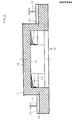
- the coke bucket 1 shows a coke bucket 1 as it is moved within the shaft frame 2 after it has been lifted from the trolley.
- the coke bucket 1 hangs in a gripping tableware 3, the hooks of which are pivoted behind the gripping cams 4, so that the bucket assumes a sufficiently stable position during the movement within the shaft frame 2.
- the interior 7 of the coke bucket 1 is, as mentioned, designed so that it can hold up to 40 tons and more glowing coke.
- the resulting gases are largely collected within the shaft frame 2 during the process and then continuously sucked off and passed into the suction line 6, which is indicated in FIG. 2.
- the closure 1o covering the coke bucket 1 has a laterally projecting connecting piece 9.
- the connecting piece 9 of the suction line 6 approaches until the water cup seal assigned to the suction line 6 takes effect.
- the closure 10 consists, as can be seen from FIGS. 1 to 3, of the cover plate 11 arranged below the cross member 12 with the insulating material 13 and the longitudinal members 14, 15.
- the edge region of the closure is designed so that it has a sufficient support ensures on the edge 16 of the coke bucket 1.
- the longitudinal members 14, 15 are formed cantilevered over the sides 17, 18 of the coke bucket 1 and thus serve as a lid shelf or closure shelf. 3, they are connected to the short crossbeams 28, 3o, while the crossbeams 12, 29 arranged in the convex configuration of the closure 1o are connected to the longitudinal beams 14, 15 via vertical stems 31 .
- the suction pipe 2o or the suction pipes 2o are connected in the deepest arc 21, so that a uniform and safe suction with a low suction speed is ensured as soon as the connection between the suction line 6 and the suction pipe 2o or connecting piece 9 is established. 'represents.
- the suction pipes 2o have a rectangular cross section and can be closed with flaps 22, so that the gas escape from the suction pipes 2o into the atmosphere is considerably more difficult during the movement of the coke bucket 1 within the shaft frame 2.
- Fig. 3 illustrates that the convex design of the closure 1o remains limited to the central region 26, while the edge regions 24, 25 run flat, so that the arrangement of the longitudinal beams 14, 15 is inexpensive to accomplish.
- the closure flaps 22 or the suction pipes 2o are indicated, via which dust-containing gas, which is present in the cavity formed by the convex design of the closure 1o, is sucked off.
- Fig. 4 shows the connection between suction connection piece 6 and 9 and suction tubes 2 0.
- the flaps 22 are arranged, which are automatically opened via the counterweight 33 and lever linkage 34 when the coke bucket 1 is placed on the cooling shaft. After the coke bucket 1 has been lifted off, the closure flaps 22 are then placed again so that they make it much more difficult for gases to escape from the interior of the coke bucket.
- connection between the connecting piece 9 and the suction line 6 is sealed via the water cups 32, while the closure 10 lies only on the edge 36 of the coke bucket 1.
- both connecting pieces 9 to the suction line, this is fork-shaped at the end in the form of a U-piece 38. Both connecting pieces 9, 9 'are thus evenly connected to the extraction and dedusting.
- a pipe socket 39 is formed, which can be closed by a flap 4o. This flap is opened during the suction process, so that cool and fresh air can flow in and thereby cool the gases extracted from the coke bucket 1. This makes it possible to dedust the extracted gases at the end of the suction line 6 via a cloth filter.
- the flap 4o is opened more or less, depending on the amount of gas and the gas temperature.
Landscapes
- Chemical & Material Sciences (AREA)
- Engineering & Computer Science (AREA)
- Materials Engineering (AREA)
- Oil, Petroleum & Natural Gas (AREA)
- Organic Chemistry (AREA)
- Coke Industry (AREA)
Applications Claiming Priority (2)
| Application Number | Priority Date | Filing Date | Title |
|---|---|---|---|
| DE3206938 | 1982-02-26 | ||
| DE3206938A DE3206938C2 (de) | 1982-02-26 | 1982-02-26 | Verfahren zur Kokstrockenkühlung und Verschluß für einen Kokskübel |
Publications (4)
| Publication Number | Publication Date |
|---|---|
| EP0087694A2 true EP0087694A2 (fr) | 1983-09-07 |
| EP0087694A3 EP0087694A3 (en) | 1985-01-16 |
| EP0087694B1 EP0087694B1 (fr) | 1987-04-29 |
| EP0087694B2 EP0087694B2 (fr) | 1990-09-12 |
Family
ID=6156770
Family Applications (1)
| Application Number | Title | Priority Date | Filing Date |
|---|---|---|---|
| EP83101556A Expired - Lifetime EP0087694B2 (fr) | 1982-02-26 | 1983-02-18 | Benne de coke avec couvercle |
Country Status (4)
| Country | Link |
|---|---|
| US (2) | US4521279A (fr) |
| EP (1) | EP0087694B2 (fr) |
| JP (1) | JPS5949274B2 (fr) |
| DE (2) | DE3206938C2 (fr) |
Families Citing this family (3)
| Publication number | Priority date | Publication date | Assignee | Title |
|---|---|---|---|---|
| DE3739789A1 (de) * | 1987-11-24 | 1989-06-08 | Ruhrkohle Ag | Kokstrockenkuehlung |
| CN101831311B (zh) * | 2010-05-18 | 2012-12-26 | 中国一冶集团有限公司 | 利用临时小车从干熄焦提升机井架中安装、拆除焦罐盖的施工方法 |
| CN106118694B (zh) * | 2016-08-17 | 2021-11-19 | 本钢板材股份有限公司 | 一种干熄焦水封槽 |
Family Cites Families (9)
| Publication number | Priority date | Publication date | Assignee | Title |
|---|---|---|---|---|
| DE381408C (de) * | 1922-08-03 | 1923-09-20 | Still Fa Carl | Vorrichtung zum Verladen von gluehendem Koks aus Koksoefen in Verladekuebel |
| SU518961A1 (ru) * | 1974-07-12 | 1978-07-05 | Государственный Всесоюзный Институт По Проектированию Предприятий Коксохимической Промышленности Министерства Черной Металлургии Ссср | Устройство дл загрузки коксом камеры сухого тушени |
| DE2455830A1 (de) * | 1974-11-26 | 1976-06-10 | Hartung Kuhn & Co Maschf | Geschlossener behaelterwagen fuer den transport von gluehendem koks aus den ofenkammern von horizontalen verkokungsbatterien zu einer stationaeren loeschstation |
| JPS5161502A (en) * | 1974-11-27 | 1976-05-28 | Nippon Kokan Kk | Kookusuno kanshikishokaroniokeru hatsujinboshisochi |
| JPS5628182Y2 (fr) * | 1976-01-14 | 1981-07-04 | ||
| DE2815739C3 (de) * | 1978-04-12 | 1981-03-12 | Didier Engineering Gmbh, 4300 Essen | Verschlußeinrichtung für die Füllöffnung einer Kühlkammer einer Anlage zur trockenen Kokskühlung |
| CH637869A5 (de) * | 1979-06-19 | 1983-08-31 | Microbo Ag | Handhabungseinrichtung, insbesondere fuer industrieroboter. |
| JPS56116782A (en) * | 1980-02-19 | 1981-09-12 | Nippon Kokan Kk <Nkk> | Coke dry quenching facility |
| DE3011575C2 (de) * | 1980-03-26 | 1982-09-30 | Didier Engineering Gmbh, 4300 Essen | Befülleinrichtung für Kokstrockenkühlkammern |
-
1982
- 1982-02-26 DE DE3206938A patent/DE3206938C2/de not_active Expired
-
1983
- 1983-02-09 US US06/465,254 patent/US4521279A/en not_active Expired - Fee Related
- 1983-02-18 EP EP83101556A patent/EP0087694B2/fr not_active Expired - Lifetime
- 1983-02-18 DE DE8383101556T patent/DE3371221D1/de not_active Expired
- 1983-02-24 JP JP58028663A patent/JPS5949274B2/ja not_active Expired
-
1984
- 1984-04-18 US US06/601,445 patent/US4559107A/en not_active Expired - Fee Related
Also Published As
| Publication number | Publication date |
|---|---|
| EP0087694B2 (fr) | 1990-09-12 |
| DE3206938A1 (de) | 1983-09-15 |
| US4559107A (en) | 1985-12-17 |
| EP0087694A3 (en) | 1985-01-16 |
| JPS58157890A (ja) | 1983-09-20 |
| JPS5949274B2 (ja) | 1984-12-01 |
| EP0087694B1 (fr) | 1987-04-29 |
| DE3206938C2 (de) | 1987-01-08 |
| DE3371221D1 (en) | 1987-06-04 |
| US4521279A (en) | 1985-06-04 |
Similar Documents
| Publication | Publication Date | Title |
|---|---|---|
| DE3521540A1 (de) | Loeschwagen fuer verkokungsoefen | |
| DE1771855A1 (de) | Vorrichtung zum emissionslosen Koksausdruecken und Koksloeschen bei horizontalen Verkokungsofenbatterien | |
| DE2553386B2 (de) | Staubfangvorrichtung für eine Koks-Trockenlöschanlage | |
| EP0087694B1 (fr) | Benne de coke avec couvercle | |
| CH650030A5 (de) | Vorrichtung fuer die loesungsmittelbehandlung von insbesondere metallischem behandlungsgut. | |
| EP0085369B1 (fr) | Procédé pour le refroidissement à sec de coke et chambre de refroidissement | |
| DE2701005C3 (de) | Staubsammelvorrichtung für eine Kokstrockenlöscheinrichtung | |
| DE2038729A1 (de) | Entstaubungsvorrichtung | |
| DE3011575C2 (de) | Befülleinrichtung für Kokstrockenkühlkammern | |
| DE3727431A1 (de) | Behaeltersystem | |
| DE4102045A1 (de) | Kokseintragsvorrichtung mit einhausung fuer eine kokstrockenkuehlanlage | |
| EP0033446A2 (fr) | Recipient pour le transport du coke | |
| DE2135839C3 (de) | Verfahren zur Erfassung der beim Schrottchargieren und Stahlabstechen von Elektroöfen mit Direktabsaugung entstehenden Rauchgase | |
| DE60008621T2 (de) | Sauggreifer | |
| DE3428278C2 (de) | Vorrichtung für die emissionsfreie bzw. -arme Beschickung von Lagerbehältern mit staubenden Schüttgütern | |
| DE4220465C1 (de) | Umschlaganlage fuer schuettgueter | |
| DE2943319C2 (de) | Einrichtung zur Verhinderung des Austretens von Füllgasen bei mit Stampfkuchen beschickten waagerechten Kammern von Verkokungsöfen | |
| DE3204034C2 (fr) | ||
| DE3242719A1 (de) | Vorrichtung fuer die loesungsmittelbehandlung von insbes. metallischem behandlungsgut | |
| DE7603726U1 (de) | Staub- und gasdichte vorrichtung zum deckelabheben, fuellen und schliessen von fuelloechern von koksofenbatterien | |
| DE3843003C1 (fr) | ||
| DE2358145C2 (de) | Haube zum Absaugen der von einem kippbaren, mit einem Deckel versehenen Schmelzofen, insbesondere Induktionsschmelzofen, für Metalle ausgehenden staubbeladenen Dämpfe und Rauchabgase | |
| DE463418C (de) | Entleerungsvorrichtung an Gichtgas- u. dgl. Staubbehaeltern und Verfahren zur Anbringung dieser Vorrichtung waehrend des Betriebs | |
| DE683688C (de) | Vorrichtung zum Abloeschen von erhitztem Massengut, insbesondere von Schwelkoks | |
| CH657288A5 (en) | Device for coating small items and method for operating the device |
Legal Events
| Date | Code | Title | Description |
|---|---|---|---|
| PUAI | Public reference made under article 153(3) epc to a published international application that has entered the european phase |
Free format text: ORIGINAL CODE: 0009012 |
|
| 17P | Request for examination filed |
Effective date: 19830218 |
|
| AK | Designated contracting states |
Designated state(s): BE DE FR IT LU |
|
| PUAL | Search report despatched |
Free format text: ORIGINAL CODE: 0009013 |
|
| AK | Designated contracting states |
Designated state(s): BE DE FR IT LU |
|
| 17Q | First examination report despatched |
Effective date: 19860902 |
|
| GRAA | (expected) grant |
Free format text: ORIGINAL CODE: 0009210 |
|
| AK | Designated contracting states |
Kind code of ref document: B1 Designated state(s): BE DE FR IT LU |
|
| REF | Corresponds to: |
Ref document number: 3371221 Country of ref document: DE Date of ref document: 19870604 |
|
| ITF | It: translation for a ep patent filed | ||
| ET | Fr: translation filed | ||
| PLBI | Opposition filed |
Free format text: ORIGINAL CODE: 0009260 |
|
| 26 | Opposition filed |
Opponent name: KRUPP KOPPERS GMBH Effective date: 19880122 |
|
| PUAH | Patent maintained in amended form |
Free format text: ORIGINAL CODE: 0009272 |
|
| STAA | Information on the status of an ep patent application or granted ep patent |
Free format text: STATUS: PATENT MAINTAINED AS AMENDED |
|
| 27A | Patent maintained in amended form |
Effective date: 19900912 |
|
| AK | Designated contracting states |
Kind code of ref document: B2 Designated state(s): BE DE FR IT LU |
|
| ITF | It: translation for a ep patent filed | ||
| ET3 | Fr: translation filed ** decision concerning opposition | ||
| ITTA | It: last paid annual fee | ||
| EPTA | Lu: last paid annual fee | ||
| PGFP | Annual fee paid to national office [announced via postgrant information from national office to epo] |
Ref country code: LU Payment date: 19950101 Year of fee payment: 13 |
|
| PGFP | Annual fee paid to national office [announced via postgrant information from national office to epo] |
Ref country code: BE Payment date: 19950119 Year of fee payment: 13 |
|
| PGFP | Annual fee paid to national office [announced via postgrant information from national office to epo] |
Ref country code: FR Payment date: 19950120 Year of fee payment: 13 |
|
| PG25 | Lapsed in a contracting state [announced via postgrant information from national office to epo] |
Ref country code: LU Free format text: LAPSE BECAUSE OF NON-PAYMENT OF DUE FEES Effective date: 19960218 |
|
| PG25 | Lapsed in a contracting state [announced via postgrant information from national office to epo] |
Ref country code: BE Effective date: 19960228 |
|
| BERE | Be: lapsed |
Owner name: CARL STILL G.M.B.H. & CO. K.G. Effective date: 19960228 |
|
| PG25 | Lapsed in a contracting state [announced via postgrant information from national office to epo] |
Ref country code: FR Effective date: 19961031 |
|
| REG | Reference to a national code |
Ref country code: FR Ref legal event code: ST |
|
| PGFP | Annual fee paid to national office [announced via postgrant information from national office to epo] |
Ref country code: DE Payment date: 20020207 Year of fee payment: 20 |