EP0088268A2 - Marteau, dont le manche est fixé à la tête de marteau par une douille intermédiaire - Google Patents
Marteau, dont le manche est fixé à la tête de marteau par une douille intermédiaire Download PDFInfo
- Publication number
- EP0088268A2 EP0088268A2 EP83101596A EP83101596A EP0088268A2 EP 0088268 A2 EP0088268 A2 EP 0088268A2 EP 83101596 A EP83101596 A EP 83101596A EP 83101596 A EP83101596 A EP 83101596A EP 0088268 A2 EP0088268 A2 EP 0088268A2
- Authority
- EP
- European Patent Office
- Prior art keywords
- hammer
- handle
- section
- sleeve
- head
- Prior art date
- Legal status (The legal status is an assumption and is not a legal conclusion. Google has not performed a legal analysis and makes no representation as to the accuracy of the status listed.)
- Granted
Links
- 239000000853 adhesive Substances 0.000 claims abstract description 8
- 230000001070 adhesive effect Effects 0.000 claims abstract description 8
- 239000002184 metal Substances 0.000 claims description 3
- 230000007704 transition Effects 0.000 claims description 3
- 238000001035 drying Methods 0.000 claims description 2
- 229910000831 Steel Inorganic materials 0.000 description 12
- 239000010959 steel Substances 0.000 description 12
- 241000209035 Ilex Species 0.000 description 2
- 230000001681 protective effect Effects 0.000 description 2
- 210000000078 claw Anatomy 0.000 description 1
- 238000004519 manufacturing process Methods 0.000 description 1
- 238000012986 modification Methods 0.000 description 1
- 230000004048 modification Effects 0.000 description 1
- 239000002023 wood Substances 0.000 description 1
Images
Classifications
-
- B—PERFORMING OPERATIONS; TRANSPORTING
- B25—HAND TOOLS; PORTABLE POWER-DRIVEN TOOLS; MANIPULATORS
- B25D—PERCUSSIVE TOOLS
- B25D1/00—Hand hammers; Hammer heads of special shape or materials
- B25D1/12—Hand hammers; Hammer heads of special shape or materials having shock-absorbing means
-
- B—PERFORMING OPERATIONS; TRANSPORTING
- B25—HAND TOOLS; PORTABLE POWER-DRIVEN TOOLS; MANIPULATORS
- B25G—HANDLES FOR HAND IMPLEMENTS
- B25G3/00—Attaching handles to the implements
- B25G3/02—Socket, tang, or like fixings
-
- B—PERFORMING OPERATIONS; TRANSPORTING
- B25—HAND TOOLS; PORTABLE POWER-DRIVEN TOOLS; MANIPULATORS
- B25G—HANDLES FOR HAND IMPLEMENTS
- B25G3/00—Attaching handles to the implements
- B25G3/02—Socket, tang, or like fixings
- B25G3/12—Locking and securing devices
- B25G3/28—Locking and securing devices comprising wedges, keys, or like expanding means
-
- B—PERFORMING OPERATIONS; TRANSPORTING
- B25—HAND TOOLS; PORTABLE POWER-DRIVEN TOOLS; MANIPULATORS
- B25G—HANDLES FOR HAND IMPLEMENTS
- B25G3/00—Attaching handles to the implements
- B25G3/34—Attaching handles to the implements by pressing the handle on the implements; using cement or molten metal, e.g. casting, moulding, by welding or the like
Definitions
- the invention relates to a hammer, the handle of which is fastened with the interposition of a sleeve in the hammer head.
- the hammer head is provided with an oval opening, which completely penetrates the upper end of the hammer handle equipped with a protective sleeve.
- the opening in the hammer head is adapted to the shape of the end of the handle.
- a wedge preferably a ring wedge, is driven into the end of the handle.
- the hammer head can still be secured with a cross pin that penetrates both the hammer head and the handle end.
- This inwardly tapering shape of the bearing eye makes it difficult to drive in the stem end because the middle region of the bearing eye, which forms the narrowest passage, must be passed through by the stem end. If the handle end is driven in too violently, it will be damaged or even broken off, provided the protective sleeve does not enclose the handle end tightly enough and forms a secure hold.
- the invention has for its object not only to simplify the fastening of the hammer handle in the hammer head of the generic type of hammer, but also to improve it in such a way that a reliable fastening between hammer handle and hammer head is achieved.
- the sleeve is composed of a section with a round cross section and a section with an oval cross section, the handle end of the hammer handle fitted with the sleeve being drivable in a bore of the hammer head such that the section of the sleeve with the round cross-section lies completely in the bore of the hammer head and is held there in an interference fit.
- the complex widening of the bearing eye and the difficult driving in of the end of the handle is avoided in the inventive design.
- the sleeve can consist of a one-piece metal body, the section with the oval cross section being approximately twice as long as the section with the round cross section. This ensures that the hammer handle is not only held securely in the hammer head, but that the hammer handle is protected against damage when the hammer blows below the hammer head.
- the transition point between the section with the round cross section and the section with the oval cross section can be designed as a truncated cone. This simplifies the manufacture of the one-piece metal sleeve.
- the handle end of the hammer handle can be positively received in the sleeve, the head of the handle end protruding from the cylindrical part of the sleeve. This has the advantage that the free area of the end of the handle can widen when a wedge is driven in.
- the handle end of the hammer handle can be driven with the cylindrical part of the sleeve into a cylindrical bearing eye of the hammer head.
- the head of the end of the handle appropriately receives a ring wedge.
- the bearing eye of the hammer head is advantageously designed as a blind hole.
- the ring wedge used for fastening is driven into the handle end of the hammer handle by about 2 mm in order to get the correct position.
- the ring wedge is driven completely into the handle when the bottom of the blind hole is touched and spreads the end of the handle apart to ensure that the hammer head is firmly seated.
- the handle end of the hammer handle which is not completely driven into the bearing eye of the hammer head can have an annular groove which can be filled with an adhesive, the adhesive serving as a fixed bearing shell in the bearing eye of the hammer handle after drying out.
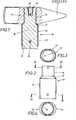
- the first handle attachment is shown in FIGS. 1-4.
- the hammer identified by the reference number 10 consists of a hammer head 11 made of steel, a wooden handle 12 and a steel sleeve 13.
- the hammer head 11 is provided with a continuous bore 14 which serves as a cylindrical bearing eye .
- the steel sleeve 13 is composed of a section 15 with a round cross section and a section 16 with an oval cross section.
- the transition point between the section 15 with the round cross section and the section 16 with the oval cross section is designed as a truncated cone 17.
- Section 16 is approximately twice as long as section 15.
- the handle end 18 of the handle 12 is equipped with the steel sleeve 13 in such a way that the head of the handle end 18 protrudes from the cylindrical section 15 of the steel sleeve 13.
- the shape of the handle end 18 is precisely adapted to the interior of the steel sleeve 13.
- the cylindrical section 15 is driven completely into the bore 14. As can be seen from FIG. 1, the cylindrical section 15 of the sleeve 13 extends over approximately two thirds of the interior of the bore 14. The remaining part of the bore 14 is filled by the handle end 18. After driving in the handle end 18, a ring wedge 19 is driven into its head, which spreads the upper part of the handle end 18 and ensures a secure hold of the handle 12 in the hammer head 11.
- An additional securing of the handle 12 in the hammer head 11 can also be effected in that the sections 15 and 16 of the steel sleeve 13 are each provided with a dowel pin 20 which crosses the hammer head 11 or the handle end 18.
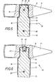
- FIG. 5 A second handle attachment is illustrated in FIG. 5.
- the handle end 18 is equipped with an annular groove 21.
- the stem end 18 is driven into the bore 14 of the hammer head 11, the free space in the bore 14 filled with a special adhesive 22. After the adhesive 22 has dried out, an optimal fit of the hammer head 11 on the handle 12 is ensured.
- the steel sleeve 13 has the same structure as the embodiment according to FIGS. 1-4. The same reference numerals have therefore been chosen for this. Even with the second handle attachment, the steel sleeve 13 is secured by additional cross pins 20 on the hammer head 11 or on the handle end 13.
- Fig. 6 shows a third handle attachment.
- the bearing eye in the hammer head 11 is designed as a blind hole 23.
- the handle end 18 provided with the steel sleeve 13 is driven into the blind hole 23.
- a ring wedge 19 is driven into the head of the handle end 18.
- the ring wedge 19 is completely driven into the handle end 18 when the bottom of the blind hole is touched.
- the head of the handle end 18 is spread, whereby a firm seat of the handle 12 in the hammer head 11 is effected.
- the hammer head 11 is still secured to the handle 12 by dowel pins 20.
- the illustrated embodiments are only examples of realizations of the invention. This is not limited to this. Various modifications and applications are still possible within the scope of the invention.
- the inner surfaces of the steel sleeve 13 could be equipped with barb-shaped projections which claw into the lateral surfaces of the stem 12 when the stem end 18 is introduced.
Landscapes
- Engineering & Computer Science (AREA)
- Mechanical Engineering (AREA)
- Percussive Tools And Related Accessories (AREA)
- Portable Nailing Machines And Staplers (AREA)
Priority Applications (1)
| Application Number | Priority Date | Filing Date | Title |
|---|---|---|---|
| AT83101596T ATE47073T1 (de) | 1982-03-10 | 1983-02-19 | Hammer, dessen stiel unter zwischenschaltung einer huelse im hammerkopf befestigt ist. |
Applications Claiming Priority (2)
| Application Number | Priority Date | Filing Date | Title |
|---|---|---|---|
| DE3208586 | 1982-03-10 | ||
| DE3208586A DE3208586C2 (de) | 1982-03-10 | 1982-03-10 | Hammer |
Publications (3)
| Publication Number | Publication Date |
|---|---|
| EP0088268A2 true EP0088268A2 (fr) | 1983-09-14 |
| EP0088268A3 EP0088268A3 (en) | 1985-12-11 |
| EP0088268B1 EP0088268B1 (fr) | 1989-10-11 |
Family
ID=6157806
Family Applications (1)
| Application Number | Title | Priority Date | Filing Date |
|---|---|---|---|
| EP83101596A Expired EP0088268B1 (fr) | 1982-03-10 | 1983-02-19 | Marteau, dont le manche est fixé à la tête de marteau par une douille intermédiaire |
Country Status (3)
| Country | Link |
|---|---|
| EP (1) | EP0088268B1 (fr) |
| AT (1) | ATE47073T1 (fr) |
| DE (1) | DE3208586C2 (fr) |
Cited By (8)
| Publication number | Priority date | Publication date | Assignee | Title |
|---|---|---|---|---|
| FR2702175A1 (fr) * | 1993-03-05 | 1994-09-09 | Loire Milourd Ets Moulin Blanc | Protecteur de manche d'outils de frappe et son procédé de montage. |
| EP0703045A1 (fr) * | 1994-08-30 | 1996-03-27 | Bremer, Hermann | Manche standard en bois avec un manchon de protection trempé et un dispositif supplémentaire pour assurer la fixation |
| EP1052069A3 (fr) * | 1999-05-05 | 2001-09-05 | General Housewares Corp. | Système amortisseur de chocs pour un outil de frappe |
| WO2007000124A1 (fr) * | 2005-06-27 | 2007-01-04 | Erwin Halder Kg | Massette plastique |
| EP1604787A4 (fr) * | 2003-02-18 | 2008-07-02 | Shusen Luo | Hache ou marteau d'assemblage solide |
| CN108161842A (zh) * | 2018-01-04 | 2018-06-15 | 中国铁路上海局集团有限公司上海动车段 | 一种多功能锤 |
| FR3079156A1 (fr) * | 2018-03-21 | 2019-09-27 | Mob Mondelin Sas | Procede de fabrication d'un outil de frappe |
| CN110974344A (zh) * | 2020-01-06 | 2020-04-10 | 何福友 | 一种可调式骨科手术器械 |
Families Citing this family (2)
| Publication number | Priority date | Publication date | Assignee | Title |
|---|---|---|---|---|
| DE3913739A1 (de) * | 1989-04-26 | 1990-10-31 | Cdp Handwerkzeug Gmbh & Co Kg | Handhammer |
| DE202012102464U1 (de) | 2012-07-04 | 2012-08-07 | Josef Luber | Hammer |
Family Cites Families (9)
| Publication number | Priority date | Publication date | Assignee | Title |
|---|---|---|---|---|
| US1501095A (en) * | 1923-05-23 | 1924-07-15 | George F Brock | Hammer |
| US1687335A (en) * | 1925-05-26 | 1928-10-09 | Jackline Morley Pyson | Tool handle |
| CH259188A (de) * | 1947-09-06 | 1949-01-15 | Boesch Paul | Keil zur Befestigung des Stiels in einem Werkzeug. |
| AT204457B (de) * | 1955-02-18 | 1959-07-25 | Hispano Suiza Sa | Verfahren zur Herstellung von bei Gebrauchstemperatur festen pyrotechnischen Körpern |
| US2831202A (en) * | 1955-09-12 | 1958-04-22 | Vaughan & Bushnell Mfg Co | Claw hammer with metallic reenforcing sleeve between the connecting part of the handle and the eye of the head |
| DE1246629B (de) * | 1956-09-24 | 1967-08-03 | True Temper Corp | Verbindung eines Werkzeugstiels mit dem Werkzeug, insbesondere mit einem Hammerkopf |
| DE1301779B (de) * | 1966-12-23 | 1969-08-21 | Berg & Co | Hammer od. dgl. mit durch eine Huelse gesichertem, aus Holz bestehendem Stiel |
| FR2253608A1 (en) * | 1973-12-06 | 1975-07-04 | Loire Milourd Ets Moulin Blanc | Method of fixing wooden handle to hammer head - involves surrounding split, wedged open handle end with synthetic material |
| FR2326951A1 (fr) * | 1974-03-01 | 1977-05-06 | Charlet Germain | Pioche perfectionnee pour piolet d'alpinisme |
-
1982
- 1982-03-10 DE DE3208586A patent/DE3208586C2/de not_active Expired
-
1983
- 1983-02-19 EP EP83101596A patent/EP0088268B1/fr not_active Expired
- 1983-02-19 AT AT83101596T patent/ATE47073T1/de not_active IP Right Cessation
Cited By (12)
| Publication number | Priority date | Publication date | Assignee | Title |
|---|---|---|---|---|
| FR2702175A1 (fr) * | 1993-03-05 | 1994-09-09 | Loire Milourd Ets Moulin Blanc | Protecteur de manche d'outils de frappe et son procédé de montage. |
| EP0615819A1 (fr) * | 1993-03-05 | 1994-09-21 | FORGES DE LA LOIRE ET DE MILOURD ETABLISSEMENTS MOULIN BLANC Société Anonyme | Protecteur de manche d'outils de frappe et son procédé de montage |
| EP0703045A1 (fr) * | 1994-08-30 | 1996-03-27 | Bremer, Hermann | Manche standard en bois avec un manchon de protection trempé et un dispositif supplémentaire pour assurer la fixation |
| EP1052069A3 (fr) * | 1999-05-05 | 2001-09-05 | General Housewares Corp. | Système amortisseur de chocs pour un outil de frappe |
| US6363817B1 (en) | 1999-05-05 | 2002-04-02 | General Housewares Corporation | Shock absorption system for a striking tool |
| EP1604787A4 (fr) * | 2003-02-18 | 2008-07-02 | Shusen Luo | Hache ou marteau d'assemblage solide |
| WO2007000124A1 (fr) * | 2005-06-27 | 2007-01-04 | Erwin Halder Kg | Massette plastique |
| US7703355B2 (en) | 2005-06-27 | 2010-04-27 | Erwin Halder Kg | Recoilless hammer |
| CN108161842A (zh) * | 2018-01-04 | 2018-06-15 | 中国铁路上海局集团有限公司上海动车段 | 一种多功能锤 |
| CN108161842B (zh) * | 2018-01-04 | 2023-11-28 | 中国铁路上海局集团有限公司上海动车段 | 一种多功能锤 |
| FR3079156A1 (fr) * | 2018-03-21 | 2019-09-27 | Mob Mondelin Sas | Procede de fabrication d'un outil de frappe |
| CN110974344A (zh) * | 2020-01-06 | 2020-04-10 | 何福友 | 一种可调式骨科手术器械 |
Also Published As
| Publication number | Publication date |
|---|---|
| EP0088268A3 (en) | 1985-12-11 |
| EP0088268B1 (fr) | 1989-10-11 |
| ATE47073T1 (de) | 1989-10-15 |
| DE3208586A1 (de) | 1983-09-29 |
| DE3208586C2 (de) | 1986-12-11 |
Similar Documents
| Publication | Publication Date | Title |
|---|---|---|
| DE2827031C3 (de) | Befestigungseinrichtung | |
| DE4003374C1 (fr) | ||
| DE2116808A1 (de) | Befestigungsvorrichtung | |
| DE2053444A1 (de) | Zweiteilige Verbindung fur Bauteile | |
| EP0088268A2 (fr) | Marteau, dont le manche est fixé à la tête de marteau par une douille intermédiaire | |
| EP0572607B1 (fr) | Dispositif d'insertion et de pose de rivets aveugles tirants autoforeurs | |
| DE3731459C1 (de) | Schneidrad fuer Saug- oder Schaufelradbagger | |
| DE2047022A1 (de) | Anordnung zur Befestigung eines Steck Schlüssels auf einer Antriebswelle | |
| DE29721119U1 (de) | Dübel zur Befestigung von Möbelbeschlagteilen | |
| EP0406801A1 (fr) | Dispositif de fixation | |
| DE2613309B2 (de) | Vorrichtung zum Befestigen und Lösen der Verriegelung zwischen einer Arbeitsspindel und einem in deren Aufnahme eingesetzten kegeligen Werkzeugschaft | |
| DE3527053C2 (fr) | ||
| DE2209471C2 (de) | Zinkenbefestigung für eine Egge, insbesondere für eine Kreiselegge | |
| DE8206621U1 (de) | Hammer, dessen stiel unter zwischenschaltung einer huelse im hammerkopf befestigt ist | |
| DE3229200C2 (de) | Schreibgerät mit Klipp | |
| DE4032064A1 (de) | Bergbaubohrkrone | |
| DE8706939U1 (de) | Befestigung einer Tretkurbel an der Tretkurbelwelle eines Fahrrades | |
| DE2802288C3 (de) | Spannvorrichtung für Kettenstränge | |
| DE589699C (de) | Verbindung von Kappenisolatoren in Haengeketten mittels eines Bolzens, dessen Kopf in einer schalenfoermigen Tasche der Isolatorkappe gelagert ist | |
| CH666805A5 (de) | Kupplung fuer aerztliche, insbesondere zahnaerztliche handstueckteile. | |
| DE2047022C (de) | Anordnung zur Befestigung eines Steckschlüssels auf einer Antriebswelle | |
| DE8126129U1 (de) | Nageldübel | |
| DE8325957U1 (de) | Handhammer | |
| DE2302426C3 (de) | Hammer mit Kunststoffstiel | |
| DE19716340C2 (de) | Modelstift mit Führungshülse zur lösbaren und exakten Positionierung von Zahnkranz- bzw. Kiefersegmenten auf einer Modelbasis |
Legal Events
| Date | Code | Title | Description |
|---|---|---|---|
| PUAI | Public reference made under article 153(3) epc to a published international application that has entered the european phase |
Free format text: ORIGINAL CODE: 0009012 |
|
| AK | Designated contracting states |
Designated state(s): AT BE CH DE FR IT LI NL |
|
| PUAL | Search report despatched |
Free format text: ORIGINAL CODE: 0009013 |
|
| AK | Designated contracting states |
Designated state(s): AT BE CH DE FR IT LI NL |
|
| 17P | Request for examination filed |
Effective date: 19860117 |
|
| 17Q | First examination report despatched |
Effective date: 19871009 |
|
| ITF | It: translation for a ep patent filed | ||
| GRAA | (expected) grant |
Free format text: ORIGINAL CODE: 0009210 |
|
| AK | Designated contracting states |
Kind code of ref document: B1 Designated state(s): AT BE CH FR IT LI NL |
|
| REF | Corresponds to: |
Ref document number: 47073 Country of ref document: AT Date of ref document: 19891015 Kind code of ref document: T |
|
| ET | Fr: translation filed | ||
| PLBE | No opposition filed within time limit |
Free format text: ORIGINAL CODE: 0009261 |
|
| STAA | Information on the status of an ep patent application or granted ep patent |
Free format text: STATUS: NO OPPOSITION FILED WITHIN TIME LIMIT |
|
| 26N | No opposition filed | ||
| ITTA | It: last paid annual fee | ||
| PGFP | Annual fee paid to national office [announced via postgrant information from national office to epo] |
Ref country code: FR Payment date: 19940114 Year of fee payment: 12 |
|
| PGFP | Annual fee paid to national office [announced via postgrant information from national office to epo] |
Ref country code: CH Payment date: 19940117 Year of fee payment: 12 |
|
| PGFP | Annual fee paid to national office [announced via postgrant information from national office to epo] |
Ref country code: BE Payment date: 19940209 Year of fee payment: 12 |
|
| PGFP | Annual fee paid to national office [announced via postgrant information from national office to epo] |
Ref country code: AT Payment date: 19940224 Year of fee payment: 12 |
|
| PGFP | Annual fee paid to national office [announced via postgrant information from national office to epo] |
Ref country code: NL Payment date: 19940228 Year of fee payment: 12 |
|
| PG25 | Lapsed in a contracting state [announced via postgrant information from national office to epo] |
Ref country code: AT Effective date: 19950219 |
|
| PG25 | Lapsed in a contracting state [announced via postgrant information from national office to epo] |
Ref country code: LI Effective date: 19950228 Ref country code: CH Effective date: 19950228 Ref country code: BE Effective date: 19950228 |
|
| BERE | Be: lapsed |
Owner name: BREMER HANS-HERBERT Effective date: 19950228 |
|
| PG25 | Lapsed in a contracting state [announced via postgrant information from national office to epo] |
Ref country code: NL Effective date: 19950901 |
|
| PG25 | Lapsed in a contracting state [announced via postgrant information from national office to epo] |
Ref country code: FR Effective date: 19951031 |
|
| NLV4 | Nl: lapsed or anulled due to non-payment of the annual fee |
Effective date: 19950901 |
|
| REG | Reference to a national code |
Ref country code: FR Ref legal event code: ST |