EP0088461A1 - Elektrode zur elektrolytischen Gasherstellung und Elektrolysezelle mit selektiv-durchlässiger Membran - Google Patents
Elektrode zur elektrolytischen Gasherstellung und Elektrolysezelle mit selektiv-durchlässiger Membran Download PDFInfo
- Publication number
- EP0088461A1 EP0088461A1 EP83200233A EP83200233A EP0088461A1 EP 0088461 A1 EP0088461 A1 EP 0088461A1 EP 83200233 A EP83200233 A EP 83200233A EP 83200233 A EP83200233 A EP 83200233A EP 0088461 A1 EP0088461 A1 EP 0088461A1
- Authority
- EP
- European Patent Office
- Prior art keywords
- electrolysis
- plate
- zone
- electrode
- electrolyte
- Prior art date
- Legal status (The legal status is an assumption and is not a legal conclusion. Google has not performed a legal analysis and makes no representation as to the accuracy of the status listed.)
- Granted
Links
Images


Classifications
-
- C—CHEMISTRY; METALLURGY
- C25—ELECTROLYTIC OR ELECTROPHORETIC PROCESSES; APPARATUS THEREFOR
- C25B—ELECTROLYTIC OR ELECTROPHORETIC PROCESSES FOR THE PRODUCTION OF COMPOUNDS OR NON-METALS; APPARATUS THEREFOR
- C25B11/00—Electrodes; Manufacture thereof not otherwise provided for
- C25B11/02—Electrodes; Manufacture thereof not otherwise provided for characterised by shape or form
- C25B11/03—Electrodes; Manufacture thereof not otherwise provided for characterised by shape or form perforated or foraminous
-
- C—CHEMISTRY; METALLURGY
- C25—ELECTROLYTIC OR ELECTROPHORETIC PROCESSES; APPARATUS THEREFOR
- C25B—ELECTROLYTIC OR ELECTROPHORETIC PROCESSES FOR THE PRODUCTION OF COMPOUNDS OR NON-METALS; APPARATUS THEREFOR
- C25B11/00—Electrodes; Manufacture thereof not otherwise provided for
- C25B11/02—Electrodes; Manufacture thereof not otherwise provided for characterised by shape or form
Definitions
- the present invention relates to an electrode for the production of gas by electrolysis, as well as to a membrane electrolysis cell, with selective permeability, equipped with such an electrode.
- Membrane electrolysis cells with selective permeability are well known in the art, where they are used in particular for the production of hydrogen and a halogen by electrolysis of an aqueous solution of alkali metal halide, for example for the production of hydrogen, chlorine and an aqueous solution of sodium hydroxide by electrolysis of sodium chloride brine. They are generally formed by an alternation of anodes and vertical cathodes, between which membranes with selective permeability are interposed so as to delimit electrolysis chambers which are alternately anodic and cathodic and are in communication with supply conduits electrolytes and enclosures for the recovery of electrolysis products.
- the anode chambers are in communication with a conduit for the supply of a concentrated aqueous solution of chloride of sodium and with an enclosure for the recovery of chlorine and a dilute solution of sodium chloride and the cathode chambers are in communication with a supply conduit serving for the introduction of water or a dilute solution of sodium hydroxide and with an enclosure for the recovery of hydrogen and a concentrated solution of sodium hydroxide.
- this known electrolysis cell thus has the disadvantage of requiring a large footprint on the ground and imposing high investment costs.
- the invention overcomes the disadvantages of known electrolysis cells, by providing an electrode of new design, which greatly improves the efficiency of electrolysis cells, especially cells with selective permeability membrane, while allowing productivity high, high energy efficiency and reduced footprint.
- the invention relates to an electrode for the production of gas by electrolysis, comprising a vertical plate pierced with openings for the passage of an electrolyte and of gas, in which the plate comprises, on one face, at least one zone electrolysis free of openings, between a lower opening connected to an electrolyte supply conduit and an upper opening connected to a gas and electrolyte evacuation conduit, the conduits being arranged on the other face of the plate.
- the electrolysis zone is a surface zone of the plate, which effectively participates in the electrolysis and on which the gas is generated.
- a plate is made of a film-forming material chosen from titanium, tantalum, tungsten, niobium, zirconium and the alloys of these metals, carrying, in its electrolysis zone a conductive coating of an anode active material chosen from platinum, iridium, osmium, palladium, rhodium, ruthenium, the alloys of these metals and the compounds, for example the oxides, of these metals.
- the coating of the anode may advantageously comprise one of the active anode materials described in patents BE-A 769677, BE-A 769680, BE-A 784255 and BE-A 785605 (SOLVAY & Cie) ..
- the plate can be in mild steel or nickel, optionally covered, in its electrolysis zone, with an active conductive coating chosen from oxidized compounds of the spinel type, for example magnetite, or obtained by thermal decomposition of a thermodecomposable compound of a metal chosen from cobalt, iron, manganese and nickel, as suggested in patents FR-A 2434213 and FR-A 2460343 (SOLVAY & Cie).
- an active conductive coating chosen from oxidized compounds of the spinel type, for example magnetite, or obtained by thermal decomposition of a thermodecomposable compound of a metal chosen from cobalt, iron, manganese and nickel, as suggested in patents FR-A 2434213 and FR-A 2460343 (SOLVAY & Cie).
- the electrolysis area of the electrode is free of openings and is arranged between a lower opening and an upper opening which are respectively in communication with an electrolyte supply conduit and with a conduit evacuation of the electrolyte and of the gas generated on the electrolysis zone; these two conduits are arranged on the rear face of the plate.
- the lower opening and the upper opening may each consist of a single opening of large section or of a plurality of orifices. It is advantageous for the openings to extend as far as possible over the horizontal width of the electrolysis zone. For this purpose, they can for example consist of a very elongated rectangle, horizontal or slightly inclined, or in a horizontal or slightly inclined row of several orifices such as circular, oval, square or rectangular perforations.
- the overall section of the upper opening is chosen as a function of that of the lower opening and the height of the electrolysis zone, so as to ensure a regular regular flow of the electrolyte and the gas along of the active area of the electrode.
- the height of the electrolysis zone is generally limited so as to ensure a regular upward flow of the electrolyte by gazosiphon in contact with it and to achieve an acceptable current density over its entire surface.
- the choice of the optimum height is conditioned by the search for an acceptable compromise between a maximum electrolysis energy efficiency, favored by a low height, and maximum productivity for a minimum investment, favored by a large height.
- the choice of the optimum height of the electrolysis zone depends on the nature of the gas to be produced, the electrolyte used and the current density chosen.
- the electrode according to the invention has the advantageous characteristic of having its electrolysis zone supplied with a gas-free electrolyte, from its lower part, the gas produced being discharged with the electrolyte at the upper part of the zone electrolysis.
- the arrangement of the conduits serving for the supply of the electrolyte and for the evacuation of the gas and the electrolyte on the rear face of the plate makes it possible to provide thereon several stepped electrolysis zones, each delimited between a lower opening and an upper opening. This feature of the invention makes it possible to produce very high electrodes having several stepped electrolysis zones of reduced height, thereby ensuring high productivity with maximum energy efficiency.
- the gas evacuation duct opens into a chimney common to all the electrolysis zones, delimited between the plate, a vertical partition arranged opposite the latter and a peripheral frame joining the plate to the partition.
- This embodiment of the invention has the advantage of ensuring rapid and easy evacuation of the gas produced and of causing a rapid upward flow of the electrolyte along the active areas of the plate, by gazosiphon. All other things remaining equal, this upward flow is all the faster the higher the plate and the chimney and the greater the number of electrolysis zones.
- good results have been obtained with electrodes in accordance with the invention, comprising three to five stepped electrolysis zones, each having a height of between 8 and 15 cm.
- Electrodes of greater height for example two meters high or more, having from eight to twelve or more stepped electrolysis zones, the height of which is fixed between 5 and 15 cm.
- the choice of very high electrodes comprising a large number of electrolysis zones makes it possible to reduce the width of the electrodes. This results in the advantage of a reduction in current losses by the Joule effect through the electrodes, in the case of electrolysis cells where the electrodes are supplied with current along a vertical lateral edge.
- the electrolyte supply conduit of each electrolysis zone advantageously consists of a tubular conduit arranged parallel to the plate, at the inside the chimney, and open opposite the lower opening of said electrolysis zone.
- the electrode is a unipolar electrode, in which the aforementioned partition comprises, on its face external to the chimney, at least one electrolysis zone between an upper opening in communication with the chimney and a lower opening in communication with a tubular conduit for the supply of electrolyte, housed in the chimney, parallel to the partition.
- the electrode according to the invention finds a particularly advantageous application as an anode or cathode for the production of a gas in an electrolysis cell with a membrane with selective permeability.
- the invention therefore also relates to an electrolysis cell comprising a membrane with selective permeability interposed between a pair of vertical electrodes, at least one of which is the seat of a gas emission during the electrolysis of a electrolyte, conforms to the electrode described above, the cell comprising at least one electrolysis chamber delimited by the membrane, an electrode as described above and a peripheral seal interposed between the membrane and the electrode.
- membrane with selective permeability is understood to mean a thin, non-porous membrane comprising an ion-exchange material.
- the choice of the material constituting the membrane and of its ion exchange material will depend on the nature of the electrolytes subjected to the electrolysis and on the products which it is sought to obtain.
- the material of the membrane is chosen from those which are capable of withstanding the thermal and chemical conditions normally prevailing in the cell during electrolysis, the ion-exchange material being chosen from anion-exchange materials or materials cation exchangers, depending on the electrolysis operations for which the cell is intended.
- membranes which are well suited are cationic polymer membranes fluorinated, preferably perfluorinated, containing cationic functional groups derived from sulfonic acids, acids carboxylic or phosphonic acids or mixtures of such functional groups.
- membranes of this type are those described in patents GB-A 1497748 and GB-A 1497749 (ASARI KASEI KOGYO KK), GB-A 1518387, GB-A 1522877 and US-A 4126588 (ASAHI GLASS COMPANY Ltd) and GB-A 1402920 (DIAMOND SHAMROCK CORP).
- Membranes which are particularly suitable for this application of the cell according to the invention are those known under the names "NAFION” (DU PONT DE NEMOURS & Co) and "FLEMION” (ASAHI GLASS COMPANY Ltd).
- the seal can be made of any elastic and inert material capable of withstanding the chemical and thermal environment normally prevailing in the cell during its operation; its mechanical strength and elasticity must be sufficient for it to withstand the internal pressure of the electrolysis chamber and ensure an effective seal thereof.
- a synthetic rubber such as an elastomeric copolymer of ethylene and propylene known under the brand "DUTRAL” (MONTEDISON) or a elastomeric copolymer of vinylidene fluoride and hexafluorpropylene, known under the brand "VITON” (EIDU PONT DE NEMOURS & Co).
- the electrodes according to the invention can be of the monopolar type or of the bipolar type.
- the peripheral frame of the electrode may be made of metal and connected directly to the electrical conductors; alternatively, these can be coupled to a lateral extension of the electrode plates in which case the frame can be either of metal or of a material which is not electrically conductive.
- a cell with bipolar electrodes these are each formed of a pair of plates as described above, one of which is an anode plate and the other, a cathode plate, the two plates being assembled on both sides of a peripheral frame and isolated by a hermetic vertical wall inside the frame.
- the electrical connection between the two plates can be ensured by the frame, which is then made of metal, or by electrical conductors joining the plates to one another, through the wall.
- the electrode according to the invention as described above, which equips it, comprises a plate having at least two stepped electrolysis zones, separated by an inactive zone between the upper opening of the lower electrolysis zone and the lower opening of the upper electrolysis zone, and the peripheral seal between said plate and the membrane comprises at least one transverse strip interposed between the membrane and the inactive area of the electrode plate.
- the intermediate transverse strip of the seal divides the electrolysis chamber into two superimposed parts each corresponding to an individual electrolysis zone of the plate of the electrode.
- each of the abovementioned parts of the electrolysis chamber is individually supplied with electrolyte at its lower part, via the lower opening of the corresponding electrolysis zone, the electrolyte undergoes an upward movement therein by gasosiphon, by the gas generated by electrolysis and is evacuated with it by the upper opening of said electrolysis zone.
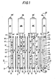
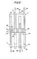
- the cell shown in Figures 1 to 6 is intended for the production of chlorine, hydrogen and an aqueous solution of sodium hydroxide, by electrolysis of a sodium chloride brine. It is of the filter press type and comprises a vertical end anode 1 and a vertical end cathode 2, between which alternate vertical anodes 3, membranes 4 with selective permeability and cathodes 5.
- Membranes 4 are membranes cationic agents such as those known under the names "NAFION” (DU PONT DE NEMOURS & Co) or "FLEMION” (ASAHI GLASS Co) which have been explained above.
- the seals 6 are made of an elastic, waterproof, non-conductive material electricity and capable of withstanding chlorine, for example an elastomeric copolymer of ethylene and propylene known under the brand "DUTRAL" (MONTEDISON). They include an intermediate horizontal strip 9 which divides the anode 7 and cathode 8 chambers into two superimposed parts.
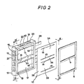
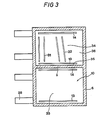
- the end anode 1 shown in detail in Figures 2 to 4, is box-shaped and formed of a vertical plate 10 of titanium and a vertical partition 11 of titanium connected together by a rigid peripheral frame 12 in titanium.
- the plate 10 On its face oriented towards the membrane 4, the plate 10 includes an electrolysis zone lower 33, an upper electrolysis zone 34 and an intermediate inactive zone 35.
- the electrolysis zones 33 and 34 each extend between a lower horizontal slot 13 and an upper horizontal slot 14; between these slots, the electrolysis zones 33 and 34 are free of openings.
- the electrolysis zones 33 and 34 are intended to participate in the production of chlorine by electrolysis of an aqueous solution of sodium chloride and for this purpose they carry a conductive coating formed from a mixture of ruthenium oxide and dioxide titanium.
- the intermediate zone 35 is defined as being an inactive zone, since it does not have the main function of being the site of production of chlorine during the electrolysis. It is intended to receive the horizontal strip 9 of the seal 6, to isolate the two parts of the electrolysis chamber.
- the plate 10 also has a vertical marginal strip 36 beyond the slots 13 and 14, the role of which will be explained below.
- the inactive zone 35 and the vertical lateral strip 36 can be free of active conductive coating or wear one, like the electrolysis zones 33 and 34.
- the upper slots 14 of the electrolysis zones 33 and 34 both open into a common chimney 15 delimited between the plate 10, the partition 11, the frame 12 and a vertical transverse panel 16.
- the lower slots 13 each open into a conduit of individual tubular supply 17 secured to the rear face of the plate 10, inside the chimney 15.
- the tubular conduits 17 are closed at 18 and open through the panel 16, into a common cavity 19 delimited between the panel 16, the frame 12, the partition 11 and the vertical strip 36 of the plate 10.
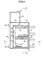
- the cavity 19 is in communication with a chamber 20 (FIG. 4), via orifices 21 formed in a vertical spar of the frame 12.
- a tube 22 connects the chamber 20 to a general adductor of a concentrated aqueous solution of sodium chloride, not shown.
- Ports 23, formed in the upper horizontal beam 42 of the frame 12 ensure the communication of the chimney 15 with the upper zone 24 of the chamber 20, which is open at 25 and is surmounted by an enclosure 26 of large horizontal section, serving recovering the chlorine produced at the anode during electrolysis and separating the anolyte entrained with it.
- a tube 27 opening into the bottom of the chamber 20 serves for the evacuation of at least a fraction of the anolyte separated from the gas which escapes through a tube 46 at the top of the chamber 26.
- Metal plates 28, for example copper, are welded to a vertical spar of the frame 12, to allow its coupling to a source of electric current, not shown.
- the intermediate anode 3 (Fig. 1 and 5) differs from the anode 1, only in that the partition 11 is replaced there by a plate 29 identical to the plate 10 and pierced by two horizontal slots 14 both opening in the chimney 15 and two horizontal slots 13 each opening into an individual tubular conduit 17.
- the plate 29 thus also has two active electrolysis zones 33 and 34 and an inactive zone 35 intended to receive the intermediate strip 9 of a seal 6.
- Cathodes 2 and 5 are of a construction similar to that of anodes 1 and 3, except that they are made of steel or nickel.
- the constituent elements of cathodes 2 and 5 bear the same reference numbers as their counterparts of anodes 1 and 3, with a prime index to differentiate them.
- the tubing 22 ' is connected to a general adductor for the admission of water or a dilute solution of sodium hydroxide (containing for example 10X by weight of sodium hydroxide), the tubing 27' serves to draw from the chamber 20 'a concentrated aqueous solution of sodium hydroxide (containing for example of the order of 25 to 40X by weight of sodium hydroxide) and the tube 46' is used for the evacuation of the hydrogen .
- the anodes 1 and 3 are arranged head to tail relative to the cathodes 2 and 5, of so that the chambers 26 'of the cathodes are arranged opposite the corresponding chambers 26 of the anodes.
- This arrangement has various advantages: on the one hand, it accommodates enclosures 26 and 26 'of large width, which is favorable for good separation of gases and electrolytes; on the other hand, all the anode dishes 28 are located on the same side of the cell and all the cathode dishes 28 'are located on the opposite side, which simplifies their connection in bypass to a source of direct current.
- This arrangement of the anodes and cathodes of the cell according to the invention also facilitates the coupling of the tubes 22, 22 ', 27 and 27' to four general conduits for the admission and evacuation of the electrolytes.
- the dishes 28 of the anodes are coupled in bypass to the positive terminal of a direct current source and the dishes 28 'of the cathodes are coupled in bypass to the negative terminal of this Power source.
- a concentrated brine of sodium chloride is introduced through the tubes 22 into the chambers 20 of the anodes 1 and 3, from where it passes into the tubular conduits 17, via the openings 21 and the cavity 19. From the conduits 17, the brine penetrates in the anode chambers 7 through the slots 13, where it is electrolysed in contact with the electrolysis zones 33 and 34 of the anode plates 10 and 29.
- the chlorine generated in this way in the anode chambers 7 subjects the anolyte to displacement therein ascending, by gazosiphon and is evacuated with it by the upper slots 14. From the chimney 15, the chlorine and the anolyte pass into the chamber 24 then the enclosure 26 where the sudden variation in section causes the separation of the chlorine and anolyte.
- the chlorine escapes through the tubing 46 and the anolyte descends into the chamber 20; a fraction is drawn off through the tubing 27 and the remaining fraction is recycled in the tubular conduits 17 with the brine coming from the tubing 22.
- water or a dilute solution of sodium hydroxide is admitted into the chambers 20 'of the cathodes 2 and 5 through the tubing 22', from where it passes into the cathode chambers 8 via the tubular conduits 17 'and the slots 13' of the cathode plates 10 'and 29'.
- the hydrogen generated by electrolysis in the cathode chambers 8 moves there from bottom to top and is evacuated therewith with the catholyte through the slots 14 '; it passes successively in the chimney 15 'of the cathodes, then in their enclosure 26' where the hydrogen is separated from the catholyte and evacuated by the tube 46 '.
- the catholyte separated in the enclosure 26 ' descends into the chamber 20'; a fraction is drawn off through the tubing 27 'while the remaining fraction is recycled into the cavity 19' and the tubular conduits 17 ', with the water or the diluted solution admitted by the tubing 22'.
- the natural draft of the chimneys 15 and 15 ′ is generally sufficient to ensure the upward flow of the electrolytes in the anode chambers 7 and cathode chambers 8. If necessary, to further accelerate this flow and increase the productivity of the cell, a fan can be provided in a general manifold, not shown, common to the pipes 46 (46 ').
- tubular conduits 17 and 17 ′ are pierced with a row of holes 30 in their upper part, to ensure degassing of the electrolyte flowing in these conduits.
- spacers are arranged between the membranes 4 and the electrode plates 10, 29, 10 ', 29', these spacers consisting of vertical rods 31 or obliques 32 (Fig.3), which are fixed parallel to these plates by engagement of their free ends in holes made in the plates.
- These rods can for example be made of titanium in the case of anodes and of steel or nickel in the case of cathodes. They can also be made of a polymeric material, for example polytetrafluoroethylene.
- the spacing rods 31 and 32 are replaced by narrow strips, vertical or oblique, seals 6.
- FIG. 7 shows a modified embodiment of the end anode 1 of the cell of FIG. 1.
- the plate 10 comprises four stepped electrolysis zones 33, 34, 37 and 38, separated by three inactive zones 35 and each pierced with a pair of openings 13 and 14 which will be described in detail later.
- two vertical transverse panels 16 join the plate 10 to the partition 11 and thus separate the chimney 15 from two marginal cavities 19 connected together by four horizontal tubular conduits 17 applied against the plate 10 opposite the openings 13.
- the openings 13 are used for the admission of the electrolyte to the electrolysis zones 33, 34, 37 and 38 and include a horizontal slot opposite the tubular conduits 17 and extensions 39 in the vertical marginal strips 36 of the plate 10 , opposite the cavities 19.
- the openings 14 are used for the evacuation of chlorine and the anolyte and consist of horizontal slots facing the chimney 15, as in the embodiment of Figures 2 to 5. These slots 14 stop below the marginal bands 36, so that they do not communicate with the cavities 19.
- the seal 6 comprises three intermediate transverse bands 9 which each comprise a horizontal element 40 engaged between a pair of slots 13 and 14 and two inclined end elements 41 whose role will be explained below.
- the extensions 39 of the slots 13 are preferably inclined in the same direction as the elements 41 of the seal 6.
- the upper horizontal beam 42 of the frame 12 is pierced with a central orifice 23 facing the chimney 15 and a pair of orifices 21 facing the two cavities 19.
- the orifices 21 and 23 open into a large common room section, not shown, surmounting the frame 12 and similar to the chambers 26 of the cell of FIGS. 1 to 6, said chamber being in communication, at its upper part, with a chlorine discharge orifice, and at its lower part, near the side member 42 of the frame 12, with a supply pipe for a concentrated aqueous solution of sodium chloride.
- the plate 10 is further extended, beyond the frame 12, by a vertical marginal strip 45, intended to connect it to a direct current source.
- the frame 12 can be either of metal, for example titanium, or of a material which is not electrically conductive, for example of polytetrafluoroethylene.
- the two cavities 19 and the tubular conduits 17 are permanently filled with a concentrated aqueous solution of sodium chloride introduced continuously through the orifices 21.
- the solution passes through the slots 13 and their extensions 39 and is driven from bottom to top along the electrolysis zones 33, 34, 37 and 38 of the plate 10, under the effect of the gazosiphon generated by the chlorine generated therein.
- the chlorine and the anolyte are evacuated from the electrolysis zones 33, 34, 37 and 38 in the chimney 15, via the slots 14.
- the inclined elements 41 of the bands 9 of the seal 6 serve as a deflector for channeling the chlorine and the anolyte to the slots 14.
Landscapes
- Chemical & Material Sciences (AREA)
- Engineering & Computer Science (AREA)
- Chemical Kinetics & Catalysis (AREA)
- Electrochemistry (AREA)
- Materials Engineering (AREA)
- Metallurgy (AREA)
- Organic Chemistry (AREA)
- Electrolytic Production Of Non-Metals, Compounds, Apparatuses Therefor (AREA)
- Electrodes For Compound Or Non-Metal Manufacture (AREA)
- Separation Using Semi-Permeable Membranes (AREA)
Priority Applications (1)
| Application Number | Priority Date | Filing Date | Title |
|---|---|---|---|
| AT83200233T ATE20543T1 (de) | 1982-02-26 | 1983-02-15 | Elektrode zur elektrolytischen gasherstellung und elektrolysezelle mit selektiv-durchlaessiger membran. |
Applications Claiming Priority (2)
| Application Number | Priority Date | Filing Date | Title |
|---|---|---|---|
| FR8203374A FR2522338A1 (fr) | 1982-02-26 | 1982-02-26 | Electrode pour la production de gaz par electrolyse et cellule d'electrolyse a membrane a permeabilite selective |
| FR8203374 | 1982-02-26 |
Publications (2)
| Publication Number | Publication Date |
|---|---|
| EP0088461A1 true EP0088461A1 (de) | 1983-09-14 |
| EP0088461B1 EP0088461B1 (de) | 1986-06-25 |
Family
ID=9271465
Family Applications (1)
| Application Number | Title | Priority Date | Filing Date |
|---|---|---|---|
| EP83200233A Expired EP0088461B1 (de) | 1982-02-26 | 1983-02-15 | Elektrode zur elektrolytischen Gasherstellung und Elektrolysezelle mit selektiv-durchlässiger Membran |
Country Status (4)
| Country | Link |
|---|---|
| EP (1) | EP0088461B1 (de) |
| AT (1) | ATE20543T1 (de) |
| DE (1) | DE3364228D1 (de) |
| FR (1) | FR2522338A1 (de) |
Cited By (1)
| Publication number | Priority date | Publication date | Assignee | Title |
|---|---|---|---|---|
| EP0248433A3 (en) * | 1986-06-04 | 1989-02-08 | The Dow Chemical Company | Electrolytic cell |
Citations (3)
| Publication number | Priority date | Publication date | Assignee | Title |
|---|---|---|---|---|
| FR1024890A (fr) * | 1949-10-24 | 1953-04-08 | Oerlikon Maschf | Plaque d'électrode pour électrolyseurs |
| FR1028153A (fr) * | 1949-11-03 | 1953-05-20 | Montedison Spa | électrode pour électrolyseurs bipolaires |
| FR2307887A1 (fr) * | 1975-04-15 | 1976-11-12 | Asahi Glass Co Ltd | Cuve electrolytique du type filtre presse |
-
1982
- 1982-02-26 FR FR8203374A patent/FR2522338A1/fr active Granted
-
1983
- 1983-02-15 EP EP83200233A patent/EP0088461B1/de not_active Expired
- 1983-02-15 AT AT83200233T patent/ATE20543T1/de not_active IP Right Cessation
- 1983-02-15 DE DE8383200233T patent/DE3364228D1/de not_active Expired
Patent Citations (3)
| Publication number | Priority date | Publication date | Assignee | Title |
|---|---|---|---|---|
| FR1024890A (fr) * | 1949-10-24 | 1953-04-08 | Oerlikon Maschf | Plaque d'électrode pour électrolyseurs |
| FR1028153A (fr) * | 1949-11-03 | 1953-05-20 | Montedison Spa | électrode pour électrolyseurs bipolaires |
| FR2307887A1 (fr) * | 1975-04-15 | 1976-11-12 | Asahi Glass Co Ltd | Cuve electrolytique du type filtre presse |
Cited By (2)
| Publication number | Priority date | Publication date | Assignee | Title |
|---|---|---|---|---|
| EP0248433A3 (en) * | 1986-06-04 | 1989-02-08 | The Dow Chemical Company | Electrolytic cell |
| US4927509A (en) * | 1986-06-04 | 1990-05-22 | H-D Tech Inc. | Bipolar electrolyzer |
Also Published As
| Publication number | Publication date |
|---|---|
| FR2522338A1 (fr) | 1983-09-02 |
| EP0088461B1 (de) | 1986-06-25 |
| FR2522338B1 (de) | 1984-04-27 |
| DE3364228D1 (en) | 1986-07-31 |
| ATE20543T1 (de) | 1986-07-15 |
Similar Documents
| Publication | Publication Date | Title |
|---|---|---|
| JPS627275B2 (de) | ||
| EP0412600B1 (de) | Rahmen für Elektrolyseur der Filterpressenbauart und monopolarer Elektrolyseur der Filterpressenbauart | |
| FR2463199A1 (fr) | Nouvelle cellule d'electrolyse et procede pour l'electrolyse des halogenures | |
| FI71356C (fi) | Elektrodstruktur foer anvaendning i elektrolytisk cell | |
| IL45747A (en) | Electrolytic cells for the electrolysis of alkali metal chloride solutions | |
| US4584080A (en) | Bipolar electrolysis apparatus with gas diffusion cathode | |
| JPS6041717B2 (ja) | 隔膜型電解槽用陽極−膜装置 | |
| FI71357C (fi) | Monopolar elektrolyscell av filterpresstyp | |
| EP0724904B1 (de) | Elektrodialysator mit Endkasten und seine Verwendung | |
| US5314591A (en) | Electrolyzer and method of production | |
| EP0076747B1 (de) | Elektrolyseur der Filterpressenbauart | |
| CA1106314A (fr) | Cellule d'electrolyse a membrane pour la production d'un gaz | |
| EP0400712B1 (de) | Rahmen für Elektrolyseure der Filterpressenbauart und Elektrolyseure der Filterpressenbauart | |
| EP0088461B1 (de) | Elektrode zur elektrolytischen Gasherstellung und Elektrolysezelle mit selektiv-durchlässiger Membran | |
| EP0435385B1 (de) | Elektrolytische Zelle für Gas-Herstellung, die ein Stapel von senkrechten Rahmen enthält | |
| CA1334019C (fr) | Electrolyseur du type filtre-presse | |
| US4654135A (en) | Electrolytic cell for sea water | |
| US4165272A (en) | Hollow cathode for an electrolytic cell | |
| JPS5867880A (ja) | 単極性膜電解槽 | |
| LU84973A1 (fr) | Cellule d'electrolyse | |
| EP0608028A1 (de) | Elektrolyseur zur Gaserzeugung | |
| JPS5845388A (ja) | 電解槽 | |
| CA2080519A1 (fr) | Cellule d'electrolyse pour la production d'un gaz | |
| LU86982A1 (fr) | Electrode pour cellule d'electrolyse et electrolyseur du type monopolaire | |
| FR2461022A1 (fr) | Electrolyseur bipolaire a separateur synthetique |
Legal Events
| Date | Code | Title | Description |
|---|---|---|---|
| PUAI | Public reference made under article 153(3) epc to a published international application that has entered the european phase |
Free format text: ORIGINAL CODE: 0009012 |
|
| AK | Designated contracting states |
Designated state(s): AT BE CH DE FR GB IT LI NL SE |
|
| 17P | Request for examination filed |
Effective date: 19840302 |
|
| ITF | It: translation for a ep patent filed | ||
| GRAA | (expected) grant |
Free format text: ORIGINAL CODE: 0009210 |
|
| AK | Designated contracting states |
Kind code of ref document: B1 Designated state(s): AT BE CH DE FR GB IT LI NL SE |
|
| PG25 | Lapsed in a contracting state [announced via postgrant information from national office to epo] |
Ref country code: AT Effective date: 19860625 |
|
| REF | Corresponds to: |
Ref document number: 20543 Country of ref document: AT Date of ref document: 19860715 Kind code of ref document: T |
|
| PG25 | Lapsed in a contracting state [announced via postgrant information from national office to epo] |
Ref country code: SE Effective date: 19860630 |
|
| REF | Corresponds to: |
Ref document number: 3364228 Country of ref document: DE Date of ref document: 19860731 |
|
| PG25 | Lapsed in a contracting state [announced via postgrant information from national office to epo] |
Ref country code: LI Effective date: 19870228 Ref country code: CH Effective date: 19870228 |
|
| PLBE | No opposition filed within time limit |
Free format text: ORIGINAL CODE: 0009261 |
|
| STAA | Information on the status of an ep patent application or granted ep patent |
Free format text: STATUS: NO OPPOSITION FILED WITHIN TIME LIMIT |
|
| 26N | No opposition filed | ||
| REG | Reference to a national code |
Ref country code: CH Ref legal event code: PL |
|
| ITTA | It: last paid annual fee | ||
| PGFP | Annual fee paid to national office [announced via postgrant information from national office to epo] |
Ref country code: BE Payment date: 19920123 Year of fee payment: 10 |
|
| PGFP | Annual fee paid to national office [announced via postgrant information from national office to epo] |
Ref country code: GB Payment date: 19920204 Year of fee payment: 10 |
|
| PGFP | Annual fee paid to national office [announced via postgrant information from national office to epo] |
Ref country code: FR Payment date: 19920207 Year of fee payment: 10 |
|
| PGFP | Annual fee paid to national office [announced via postgrant information from national office to epo] |
Ref country code: DE Payment date: 19920228 Year of fee payment: 10 |
|
| PGFP | Annual fee paid to national office [announced via postgrant information from national office to epo] |
Ref country code: NL Payment date: 19920229 Year of fee payment: 10 |
|
| REG | Reference to a national code |
Ref country code: FR Ref legal event code: CD |
|
| ITPR | It: changes in ownership of a european patent |
Owner name: CAMBIO RAGIONE SOCIALE;SOLVAY |
|
| PG25 | Lapsed in a contracting state [announced via postgrant information from national office to epo] |
Ref country code: GB Effective date: 19930215 |
|
| PG25 | Lapsed in a contracting state [announced via postgrant information from national office to epo] |
Ref country code: BE Effective date: 19930228 |
|
| BERE | Be: lapsed |
Owner name: SOLVAY Effective date: 19930228 |
|
| PG25 | Lapsed in a contracting state [announced via postgrant information from national office to epo] |
Ref country code: NL Effective date: 19930901 |
|
| GBPC | Gb: european patent ceased through non-payment of renewal fee |
Effective date: 19930215 |
|
| NLV4 | Nl: lapsed or anulled due to non-payment of the annual fee | ||
| PG25 | Lapsed in a contracting state [announced via postgrant information from national office to epo] |
Ref country code: FR Effective date: 19931029 |
|
| PG25 | Lapsed in a contracting state [announced via postgrant information from national office to epo] |
Ref country code: DE Effective date: 19931103 |
|
| REG | Reference to a national code |
Ref country code: FR Ref legal event code: ST |