EP0088626A2 - Vorrichtung zum Steuern der Drehzahl eines drehenden Körpers - Google Patents
Vorrichtung zum Steuern der Drehzahl eines drehenden Körpers Download PDFInfo
- Publication number
- EP0088626A2 EP0088626A2 EP83301223A EP83301223A EP0088626A2 EP 0088626 A2 EP0088626 A2 EP 0088626A2 EP 83301223 A EP83301223 A EP 83301223A EP 83301223 A EP83301223 A EP 83301223A EP 0088626 A2 EP0088626 A2 EP 0088626A2
- Authority
- EP
- European Patent Office
- Prior art keywords
- signal
- tachometer
- period
- counter
- digital
- Prior art date
- Legal status (The legal status is an assumption and is not a legal conclusion. Google has not performed a legal analysis and makes no representation as to the accuracy of the status listed.)
- Withdrawn
Links
Images

Classifications
-
- G—PHYSICS
- G01—MEASURING; TESTING
- G01P—MEASURING LINEAR OR ANGULAR SPEED, ACCELERATION, DECELERATION, OR SHOCK; INDICATING PRESENCE, ABSENCE, OR DIRECTION, OF MOVEMENT
- G01P3/00—Measuring linear or angular speed; Measuring differences of linear or angular speeds
- G01P3/42—Devices characterised by the use of electric or magnetic means
- G01P3/44—Devices characterised by the use of electric or magnetic means for measuring angular speed
- G01P3/48—Devices characterised by the use of electric or magnetic means for measuring angular speed by measuring frequency of generated current or voltage
- G01P3/481—Devices characterised by the use of electric or magnetic means for measuring angular speed by measuring frequency of generated current or voltage of pulse signals
- G01P3/489—Digital circuits therefor
-
- H—ELECTRICITY
- H02—GENERATION; CONVERSION OR DISTRIBUTION OF ELECTRIC POWER
- H02P—CONTROL OR REGULATION OF ELECTRIC MOTORS, ELECTRIC GENERATORS OR DYNAMO-ELECTRIC CONVERTERS; CONTROLLING TRANSFORMERS, REACTORS OR CHOKE COILS
- H02P23/00—Arrangements or methods for the control of AC motors characterised by a control method other than vector control
- H02P23/22—Controlling the speed digitally using a reference oscillator, a speed proportional pulse rate feedback and a digital comparator
Definitions
- the present invention relates generally to the field of devices for controlling the speed of rotating bodies. More particularly, the present invention concerns an apparatus for controlling the speed of an electrically driven momentum wheel in an inertial guidance system. Specifically, the invention is embodied in a closed loop speed control system capable of regulating speed to an accuracy of better than 0.0035%.
- Analogue systems generating an electrical signal which has a magnitude proportional to the speed of the rotating body, comparing this signal with a reference sign, and employing a closed loop feedback control system to vary the speed of the rotating body to reduce the difference or error signal have been in existence from a time prior to solid state electronics.
- U.S. Patent No. 3,539,897 issued on November 10, 1978 to M. R. Sommeria covers a servo control system for controlling the position of a machine tool or part thereof, under an automated or numerical control program.
- Information about the velocity of movement of the machine is derived from a tachometer, but such information is only used to critically control the damping of the system, such that machine position lags programmed position to the least degree possible.
- U.S. Patent No. 4,056,287 issued November 1, 1977 to W. Gudat details a wheel speed measuring circuit in which a count is derived which is representative of the length of one half cycle of the sinusoidal voltage produced by the wheel sensor, while the frequency being counted is varied as an exponential function of wheel period, such that an adequately large count to ensure the desired resolution can be derived even at low wheel speeds.
- an apparatus for controlling the speed of a rotating body comprising tachometer means for deriving a periodic electrical pulse signal having a period which is inversely proportional to the rotational frequency of said body; free-running counter means connected to said tachometer means for continuously counting at a fixed frequency and accumulating a count throughout each period of said periodic pulse signal, for responding to each said periodic pulse signal by resetting said count to zero, and for continuously producing a digital electrical signal which is a numerical representation of said count at the end of the most rcent period of said periodic pulse signal; means to produce a command digital reference signal representative of the desired rotational speed of said rotating body; period comparator means for comparing said digital electrical signal with said digital reference signal and for generating in response to the difference therebetween a speed control signal having a magnitude representative of said difference; speed control means connected to said period comparator means to vary the rotational speed of said rotating body in response to said speed control signal in a sense to continuously minimise said difference between said digital electrical signal and said digital reference signal.
- the tachometer means includes a tachometer rotor mechanically coupled to the rotating body and having a plurality p of sensible poles spaced about the periphery thereof for generating a tachometer electrical signal by means of a sensor.
- a tachometer counter produces an output pulse signal for each n x p cycles of the tachometer signal where n is an integer, such that each pulse of the output signal is triggered by the passage of the same one of the p sensible poles, and variations in the spacing of the poles do not affect the output period of the tachometer counter.
- a free-running counter counts at a fixed frequency during each period of the tachometer counter, and thus accumulates a count which is an accurate representation of the length of the period.
- the count is transferred into a buffer register, and the free-running counter is then reset, such that the buffer register always contains a numerical representation of the count at the end of the most recent period of the tachometer counter.
- This numerical representation is compared with a numerical reference signal representative of the desired speed in an arithmetic-and-logical unit, and an erroi signal is produced.
- a speed control means responds t. the error signal by varying the speed of the rotating body in a sense to minimize the error.
- an electronic apparatus 1 for controlling the speed of a rotating body to a high degree of accuracy may be used to regulate the speed of a momentum wheel, as indicated by numeral 3, for example, although the apparatus will also find many other uses in speed regulation.
- momentum wheel 3 is merely representative of a large variety of rotating bodies whose speed must be precisely controlled and made to conform to a commanded, variable speed, the means for accomplishing this end will now be described.
- a tachometer which is not shown in Figure 1, but will be described later in some detail with respect to Figure 2.
- the function of this tachometer is to output a cyclic electrical tachometer signal consisting of a series of pulses on the line labeled "tach output" in Figure 1.
- This tachometer signal is counted in a tach pulse counter 5, which produces a periodic electrical pulse signal on line 7, to provide an input to a transfer and reset logic circuit 9. ,
- the tachometer signal at the input to counter 5 has a frequency which is an integral multiple p of the frequency of rotation of the momentum wheel 3.
- Counter 5 counts this incoming tachometer signal, and outputs a single pulse on line 7 after each n x p cycles of the tachometer signal, such that the frequency of the periodic electrical pulse signal on line 7 is directly proportional to the frequency of the tachometer signal, being a fraction 1/(n x p) thereof.
- Transfer and reset logic 9 detects the leading edge of each incoming pulse of the periodic electrical pulse signal on line 7, and produces in response to each pulse of this signal a transfer pulse on line 11, and a reset pulse on line 13.
- a counter 14 which might be a 16-bit digital counter for example, counts the output of a free-running, fixed frequency clock generator 17, producing a frequency of, for example, 1 MHz.
- Counter 14 provides a 16-bit numerical representation of the accumulated count on sixteen corresponding output lines 15 to a buffer register 23.
- the transfer pulse produced on line 11 by transfer and reset logic circuit 9 immediately following each pulse on line 7 "clocks" the signal present on lines 15 into register 23.
- the transfer pulse produc.ed on line 11 by transfer and reset logic circuit 9 immediately following each pulse on line 7 "clocks” the signal present on lines 15 into register 23, whereupon counters 14 and 5 are immediately reset.
- register 23 always contains the numerical representation of the count obtained at the end of the most recent period of the periodic signal on line 7. Further, since the period of the signal on line 7 is an integral multiple of the period of the rotating body represented by the momentum wheel 3, the signal present within the register is proportional to the period of wheel 3.
- the tachometer present within block 3 of Figure 1 and tach pulse counter 5 together comprise a tachometer means for deriving a periodic electrical pulse signal having a period which is inversely proportional to the rotational frequency of the rotating body, while transfer and reset logic circuit 9, clock generator 17, counter 14 and buffer register 23 together comrise a free-running counter means for continuously producing a digital electrical signal which is a numerical representation of the period of rotation of the rotating body during the most recent measuring period.
- the numerical representation of the period of the momentum wheel 3 is compared with a command reference signal to determine the difference therebetween, and correspondingly to correct the speed of the wheel 3.
- a register output line 27 is connected by means of an AND gate 21 to the input line 25 of a storage device 31, labeled register 1 in Figure 1.
- a speed command unit 37 generates a digital speed reference signal in the form of a 16-bit representation of the period corresponding to the required speed of the rotating body represented by the momentum wheel 3.
- Speed command unit 37 could be a manually set control together with the circuitry needed to translate the set speed into a numerical representation of the corresponding period, or could be some form of automatic controller accepting any of a number of inputs and deriving from them the required speed, and outputing a numerical representation Q f the corresponding period. In either case, the reference signal from unit 37 is stored in register 2, numeral 35 in Figure 1.
- An arithmetic and logic unit 39 compares the numerical signals present in registers 1 and 2, and derives from their difference an error signal in numerical or digital form.
- This error signal is sent to D to A converter 43, where it is converted into an appropriate drive signal which might be a varying DC voltage which is inputed to a wheel electronic controller 49.
- Controller 49 controls the electrical energisation supplied to the momentum wheel 3, and thus varies the speed of wheel 3 so as to minimise the speed error.
- registers 1 and 2 arithmetic and logic unit 39, and D to A converter 43 may be thought of as together comprising a period comparator means for comparing the numerical signal contained within register 23 with the reference signal produced by speed command unit 37, and deriving therefrom a proportional speed control signal.
- Overflow inhibitor 19 is connected to counter 14 to sense an overflow thereof, whereupon inhibitor 19 puts out a logic "0" to AND gate 21, thus inhibiting the transmission of false period data to register 1.
- a shift clock 47 is used to "clock" the 16 bits of data serially out of register 23 and into register 1 at, for example, a 500 kHz transfer rate.
- a data recycle line 29 is provided in order that the same sixteen bits of data should be replaced in register 23, such that the register does not at any time contain a false reading of zero.
- shift clock 47 will clock a 16-bit underspeed signal into register 1.
- this underspeed signal will be a string of 16 "0"'s.
- unit 39 will respond by producing a "full torque" control signal, representing a maximum error signal to controller 49.
- the importance of providing data recycle line 29 becomes clear. Without this line, a false full torque demand might be outputed by unit 39 to controller 49 during normal operation of the circuit, which could result in instability.
- a temporary storage register 41 serves as a "scratch-pad memory" for arithmetic and logic unit 39, storing the intermediate results of calculations.
- a sequencer 45 controls the operation of unit 39 and shift clock 47 such as to provide the above sequence of operations, resulting in the comparison of the reference signal with the signal present in register 23, and the production of a speed control signal.
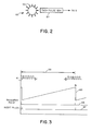
- FIG 2 illustrates in a somewhat schematic way the nature of the tachometer and sensor which produce the pulse train present on the line labeled "tach output" in Figure 1.
- the tachometer comprises a tachometer rotor 53 which either forms an integral part of the rotating body whose speed is being regulated, or else is mechanically interconnected to it in such a manner that rotor 53 is driven at the same speed.
- Substantially equispaced about the periphery of rotor 53 are a plurality of sensible poles 55, indicated generally by short radial lines in Figure 2. These poles might be the poles of a magnet or magnets in one variety of tachometer, might be alternating bands which are more or less reflective of light or other radiation, or any other form of sensible or distinguishable regions spaced about the periphery of rotor 53 for the purpose of deriving an electrical signal having a frequency proportional to rotational speed.
- a tachometer sensor in the form of a tach pulse generator 57 in close proximity to the sensible poles 55 of rotor 53 senses the passage of each pole as rotor 53 turns, and produces in response thereto a single output pulse on the line labeled "to 5" in Figure 2.
- the exact nature of tach pulse generator 57 will, of course, vary according to the nature of sensible poles 55, but it might be based upon a Hall-effect sensor, or some variety of photocell, etc.
- 61 represents the signal present on the line labeled tach output in Figure 1, and is the output of tach pulse generator 57 in Figure 2.
- Dimension line 59 in Figure 3 represents an integral multiple of the per'od of the rotating body, and might for example be the time required for three revolutions thereof. Consequently, if p represents the number of sensible poles on the periphery of rotor 53, and n represents an integer such as 3, then n x p cycles of waveform 61 will occur within the period represented by line 59. In the case of a rotor having 12 sensible poles, then, 3 complete revolutions of rotor 53 will produce exactly 36 cycles of waveform 61.
- Characteristic 63 in Figure 3 represents the successive accumulation of the count in counter 14 thoughout the period established by tach pulse counter 5.
- transfer and reset logic 9 At the end of each such period transfer and reset logic 9 generates first a transfer pulse as shown on characteristic line 65.
- This transfer pulse is on line 11 in Figure 1, and serves to clock the count from counter 14 into register 23, as already explained above.
- the transfer pulse is followed immediately by the reset pulse on characteristic 67.
- the reset pulse resets the count 63 to zero, and also resets tach pulse counter 5 and overflow inhibitor 19.
Landscapes
- Physics & Mathematics (AREA)
- General Physics & Mathematics (AREA)
- Engineering & Computer Science (AREA)
- Power Engineering (AREA)
- Control Of Electric Motors In General (AREA)
- Control Of Velocity Or Acceleration (AREA)
Applications Claiming Priority (2)
| Application Number | Priority Date | Filing Date | Title |
|---|---|---|---|
| US35657182A | 1982-03-09 | 1982-03-09 | |
| US356571 | 1982-03-09 |
Publications (2)
| Publication Number | Publication Date |
|---|---|
| EP0088626A2 true EP0088626A2 (de) | 1983-09-14 |
| EP0088626A3 EP0088626A3 (de) | 1985-07-31 |
Family
ID=23402000
Family Applications (1)
| Application Number | Title | Priority Date | Filing Date |
|---|---|---|---|
| EP83301223A Withdrawn EP0088626A3 (de) | 1982-03-09 | 1983-03-08 | Vorrichtung zum Steuern der Drehzahl eines drehenden Körpers |
Country Status (3)
| Country | Link |
|---|---|
| EP (1) | EP0088626A3 (de) |
| JP (1) | JPS58166409A (de) |
| CA (1) | CA1196997A (de) |
Cited By (5)
| Publication number | Priority date | Publication date | Assignee | Title |
|---|---|---|---|---|
| EP0157305A1 (de) * | 1984-04-02 | 1985-10-09 | Siemens Aktiengesellschaft | Schaltungsanordnung zur Drehzahlregelung eines elektronisch kommutierten Motors |
| US4760317A (en) * | 1986-07-23 | 1988-07-26 | Bien-Air Sa | Electrical arrangement for driving a rotary tool fitted in a handpiece |
| EP0380923A1 (de) * | 1989-01-09 | 1990-08-08 | Maschinenfabrik Rieter Ag | Textilmaschine, insbesondere Spinnmaschine |
| WO2000010240A3 (de) * | 1998-08-14 | 2000-06-02 | Papst Motoren Gmbh & Co Kg | Temperaturabhängige drehzahlregelung eines elektromotors mit einem mikroprozessor |
| US6825625B1 (en) | 1998-06-13 | 2004-11-30 | Ebm-Papst St. Georgen Gmbh & Co. Kg | Device with an electromotor |
Family Cites Families (9)
| Publication number | Priority date | Publication date | Assignee | Title |
|---|---|---|---|---|
| US3465228A (en) * | 1967-05-19 | 1969-09-02 | Gen Electric | Pulse width control for adjustable speed drive system |
| US3748533A (en) * | 1972-01-31 | 1973-07-24 | Beta Eng Syst Corp | Digital tachometer |
| DE2553806C3 (de) * | 1975-11-29 | 1979-03-29 | Wabco Westinghouse Gmbh, 3000 Hannover | Schaltungsanordnung zur digitalen Messung der Periodendauer einer Wechselspannung |
| DE2616972B2 (de) * | 1976-04-17 | 1979-01-11 | Wabco Westinghouse Gmbh, 3000 Hannover | Verfahren und Schaltungsanordnung zur digitalen Messung der Periodendauer eines umlaufenden Bauteiles, beispielsweise eines Fahrzeugrades |
| DE2635004B2 (de) * | 1976-08-04 | 1978-09-28 | Wabco Westinghouse Gmbh, 3000 Hannover | Verfahren und Schaltungsanordnung zur digitalen Messung der Rotationsgeschwindigkeit |
| AU515771B2 (en) * | 1978-01-17 | 1981-04-30 | Sony Corporation | Digital servo circuit |
| US4257005A (en) * | 1979-05-23 | 1981-03-17 | Hall David S | Fixed interval variable period pulse rate measuring method and system and tachometer system using same |
| FR2486731A1 (fr) * | 1980-07-11 | 1982-01-15 | Cii Honeywell Bull | Dispositif de regulation de la vitesse de rotation d'un moteur electrique |
| US4400654A (en) * | 1981-03-27 | 1983-08-23 | Magnetic Peripherals Inc. | Digital speed control for a brushless DC motor |
-
1982
- 1982-12-21 CA CA000418212A patent/CA1196997A/en not_active Expired
-
1983
- 1983-03-08 EP EP83301223A patent/EP0088626A3/de not_active Withdrawn
- 1983-03-08 JP JP58036775A patent/JPS58166409A/ja active Pending
Cited By (9)
| Publication number | Priority date | Publication date | Assignee | Title |
|---|---|---|---|---|
| EP0157305A1 (de) * | 1984-04-02 | 1985-10-09 | Siemens Aktiengesellschaft | Schaltungsanordnung zur Drehzahlregelung eines elektronisch kommutierten Motors |
| US4760317A (en) * | 1986-07-23 | 1988-07-26 | Bien-Air Sa | Electrical arrangement for driving a rotary tool fitted in a handpiece |
| EP0380923A1 (de) * | 1989-01-09 | 1990-08-08 | Maschinenfabrik Rieter Ag | Textilmaschine, insbesondere Spinnmaschine |
| US6825625B1 (en) | 1998-06-13 | 2004-11-30 | Ebm-Papst St. Georgen Gmbh & Co. Kg | Device with an electromotor |
| US7038412B2 (en) | 1998-06-13 | 2006-05-02 | Ebm-Papst St. Georgen Gmbh&Co.Kg | Device with an electromotor |
| WO2000010240A3 (de) * | 1998-08-14 | 2000-06-02 | Papst Motoren Gmbh & Co Kg | Temperaturabhängige drehzahlregelung eines elektromotors mit einem mikroprozessor |
| US6496340B1 (en) | 1998-08-14 | 2002-12-17 | Papst-Motoren Gmbh & Co. Kg | Arrangement with an electric motor |
| EP1278300A1 (de) * | 1998-08-14 | 2003-01-22 | Papst-Motoren GmbH & Co. KG | Verfahren zum Regeln der Drehzahl eines Motors, und Motor zur Durchführung eines solchen Verfahrens |
| US6819069B2 (en) | 1998-08-14 | 2004-11-16 | Ebm-Papst St. Georgen Gmbh & Co. Kg | Arrangement with an electric motor |
Also Published As
| Publication number | Publication date |
|---|---|
| EP0088626A3 (de) | 1985-07-31 |
| CA1196997A (en) | 1985-11-19 |
| JPS58166409A (ja) | 1983-10-01 |
Similar Documents
| Publication | Publication Date | Title |
|---|---|---|
| US4506312A (en) | Apparatus for controlling the speed of a rotating body | |
| EP0239026B1 (de) | Verfahren und Vorrichtung zur Bestimmung der Drehwellenposition und zur Lieferung von Kommutationssignalen | |
| EP0735664B1 (de) | Mit hoher Taktfrequenz arbeitendes Winkelregelungssystem für einen geschalteten Reluktanzmotorantrieb | |
| US4134106A (en) | Absolute resolver angle to digital converter circuit | |
| US4371819A (en) | Pulse width modulation speed control | |
| US4321580A (en) | Process and apparatus for adjustment of the angular position of a part in rotational motion | |
| US4227137A (en) | Digital tach and slip signal motor control | |
| US4298832A (en) | Digital motor speed controller | |
| US5006772A (en) | Position monitor for a stepper motor | |
| US3546553A (en) | System for maintaining a motor at a predetermined speed utilizing digital feedback means | |
| EP0088626A2 (de) | Vorrichtung zum Steuern der Drehzahl eines drehenden Körpers | |
| US4311949A (en) | Semiconductor circuit for speed control of electric motors | |
| US4028599A (en) | Method of controlling an A.C. motor | |
| US4131838A (en) | Displacement amount detecting device | |
| US4862045A (en) | Method and apparatus for controlling the number of revolutions of a rotor | |
| US4710770A (en) | Phase modulation type digital position detector | |
| US4731571A (en) | Control for stabilizing the alignment position of the rotor of a synchronous motor | |
| US3569814A (en) | Programmed digital servo control including repeated command updating whereby output function becomes smoothly varying | |
| EP0078854A1 (de) | Geschwindigkeitsdetektor | |
| US4095157A (en) | Digital servomechanism control system | |
| EP0200314A2 (de) | Regelsystem für einen elektrischen Motor | |
| US4701685A (en) | Controlling a d.c. motor | |
| US4362979A (en) | Stepping motor control circuit | |
| US4542327A (en) | Speed control apparatus | |
| EP0100757B1 (de) | Verfahren und Einrichtung zur Regelung von Wechselstromkraftwerken mit Drehmaschinen |
Legal Events
| Date | Code | Title | Description |
|---|---|---|---|
| PUAI | Public reference made under article 153(3) epc to a published international application that has entered the european phase |
Free format text: ORIGINAL CODE: 0009012 |
|
| AK | Designated contracting states |
Designated state(s): DE FR GB |
|
| PUAL | Search report despatched |
Free format text: ORIGINAL CODE: 0009013 |
|
| AK | Designated contracting states |
Designated state(s): DE FR GB |
|
| 17P | Request for examination filed |
Effective date: 19851217 |
|
| 17Q | First examination report despatched |
Effective date: 19870828 |
|
| STAA | Information on the status of an ep patent application or granted ep patent |
Free format text: STATUS: THE APPLICATION IS DEEMED TO BE WITHDRAWN |
|
| 18D | Application deemed to be withdrawn |
Effective date: 19880308 |
|
| RIN1 | Information on inventor provided before grant (corrected) |
Inventor name: NAI-TSANG, FRED Inventor name: WUETHRICH, ERNEST |