EP0088861A2 - Soupape anti-retour spécialement pour des conduites d'eau potable - Google Patents
Soupape anti-retour spécialement pour des conduites d'eau potable Download PDFInfo
- Publication number
- EP0088861A2 EP0088861A2 EP83100098A EP83100098A EP0088861A2 EP 0088861 A2 EP0088861 A2 EP 0088861A2 EP 83100098 A EP83100098 A EP 83100098A EP 83100098 A EP83100098 A EP 83100098A EP 0088861 A2 EP0088861 A2 EP 0088861A2
- Authority
- EP
- European Patent Office
- Prior art keywords
- piston tube
- cylinder
- valve body
- shut
- inlet
- Prior art date
- Legal status (The legal status is an assumption and is not a legal conclusion. Google has not performed a legal analysis and makes no representation as to the accuracy of the status listed.)
- Granted
Links
- XLYOFNOQVPJJNP-UHFFFAOYSA-N water Substances O XLYOFNOQVPJJNP-UHFFFAOYSA-N 0.000 title claims abstract description 28
- 239000007788 liquid Substances 0.000 claims abstract description 12
- 239000003651 drinking water Substances 0.000 claims abstract description 6
- 235000020188 drinking water Nutrition 0.000 claims abstract description 6
- 238000007789 sealing Methods 0.000 claims description 6
- 238000000926 separation method Methods 0.000 abstract description 9
- 238000004140 cleaning Methods 0.000 description 1
- 230000006835 compression Effects 0.000 description 1
- 238000007906 compression Methods 0.000 description 1
- 239000012530 fluid Substances 0.000 description 1
- 238000009434 installation Methods 0.000 description 1
- 238000000034 method Methods 0.000 description 1
- 230000002093 peripheral effect Effects 0.000 description 1
- 239000000126 substance Substances 0.000 description 1
- 230000007704 transition Effects 0.000 description 1
- 238000011144 upstream manufacturing Methods 0.000 description 1
- 230000000007 visual effect Effects 0.000 description 1
Images
Classifications
-
- E—FIXED CONSTRUCTIONS
- E03—WATER SUPPLY; SEWERAGE
- E03C—DOMESTIC PLUMBING INSTALLATIONS FOR FRESH WATER OR WASTE WATER; SINKS
- E03C1/00—Domestic plumbing installations for fresh water or waste water; Sinks
- E03C1/02—Plumbing installations for fresh water
- E03C1/10—Devices for preventing contamination of drinking-water pipes, e.g. means for aerating self-closing flushing valves
- E03C1/104—Devices for preventing contamination of drinking-water pipes, e.g. means for aerating self-closing flushing valves using a single check valve
-
- E—FIXED CONSTRUCTIONS
- E03—WATER SUPPLY; SEWERAGE
- E03C—DOMESTIC PLUMBING INSTALLATIONS FOR FRESH WATER OR WASTE WATER; SINKS
- E03C1/00—Domestic plumbing installations for fresh water or waste water; Sinks
- E03C1/02—Plumbing installations for fresh water
- E03C1/10—Devices for preventing contamination of drinking-water pipes, e.g. means for aerating self-closing flushing valves
- E03C1/108—Devices for preventing contamination of drinking-water pipes, e.g. means for aerating self-closing flushing valves having an aerating valve
-
- Y—GENERAL TAGGING OF NEW TECHNOLOGICAL DEVELOPMENTS; GENERAL TAGGING OF CROSS-SECTIONAL TECHNOLOGIES SPANNING OVER SEVERAL SECTIONS OF THE IPC; TECHNICAL SUBJECTS COVERED BY FORMER USPC CROSS-REFERENCE ART COLLECTIONS [XRACs] AND DIGESTS
- Y10—TECHNICAL SUBJECTS COVERED BY FORMER USPC
- Y10T—TECHNICAL SUBJECTS COVERED BY FORMER US CLASSIFICATION
- Y10T137/00—Fluid handling
- Y10T137/2496—Self-proportioning or correlating systems
- Y10T137/2544—Supply and exhaust type
- Y10T137/2557—Waste responsive to flow stoppage
-
- Y—GENERAL TAGGING OF NEW TECHNOLOGICAL DEVELOPMENTS; GENERAL TAGGING OF CROSS-SECTIONAL TECHNOLOGIES SPANNING OVER SEVERAL SECTIONS OF THE IPC; TECHNICAL SUBJECTS COVERED BY FORMER USPC CROSS-REFERENCE ART COLLECTIONS [XRACs] AND DIGESTS
- Y10—TECHNICAL SUBJECTS COVERED BY FORMER USPC
- Y10T—TECHNICAL SUBJECTS COVERED BY FORMER US CLASSIFICATION
- Y10T137/00—Fluid handling
- Y10T137/3149—Back flow prevention by vacuum breaking [e.g., anti-siphon devices]
- Y10T137/3185—Air vent in liquid flow line
- Y10T137/3294—Valved
- Y10T137/3331—With co-acting valve in liquid flow path
Definitions
- the invention relates to a pipe separator, in particular for drinking water pipes, consisting of an inlet cylinder which can be connected to a shut-off water supply line, an outlet cylinder separated therefrom by a drainage point, a displaceably arranged in one of the two cylinders, acting under the action of a return spring, and an inlet side Valve body, which closes the piston tube in the disconnected position of the piston tube when the liquid supply is shut off under the action of the return spring, but at the end of the extension movement of the piston tube then sealingly entering the other cylinder when the fluid supply is released, releases the liquid passage through the latter.
- the invention has for its object to provide a pipe separator of the type mentioned, in which it is ensured in a structurally simpler manner that the piston tube can retract into its guide cylinder when the liquid supply is shut off, that is to say it can get into its separating position without it being deliberate Leakage water passage on the circumference of the piston tube or a special drain valve is required.
- This object is achieved in that a relief channel is provided in the valve body which connects the working spaces located on both sides of it.
- the relief channel advantageously consists of a longitudinal bore provided in the valve rod end carrying the valve body and a radial radial hole.
- the relief channel in the valve body also creates the prerequisite that the piston tube is guided even better on its guide circumference in the feed cylinder and above all can also be sealed.
- the piston tube has, at its end facing the inlet connection, a ring flange which extends comparatively far in the axial direction with two sliding rings provided at the ends thereof and a sealing ring located between them, which bear against the cylinder wall in a sliding or sealing manner.
- the guide between the cylinder wall and the piston tube ring flange can now be effectively sealed, which in turn is advantageous for the return spring, which can thus be arranged directly around the piston tube without coming into contact with the flow water.
- the slide rings on both sides of the seal on the piston tube ring flange ensure constant cleaning of the cylinder guide surface, which means that any limescale or similar deposits are constantly cleared.
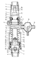
- the pipe separator shown has two cylinders with graduated diameters, namely the inlet cylinder 1 and the outlet cylinder 2, both of which are directly connected to one another via the screw flange connection 3.
- the inlet cylinder 1 is closed on the inlet side by a cover 5 provided with a centrally arranged inlet connector 4.
- a union nut 6 is seated on the inlet connection 4 for suitable connection to a pipeline provided with an upstream shut-off valve.
- a corresponding union nut 7 is also located on the outlet connector 8 of the outlet cylinder 2.
- Both the two cylinders 1, 2 and their connectors 4, 8 are coaxial with one another, so that there is an elongated, elongated design which does not require any pipeline offset for their installation.
- the piston tube 9 is axially displaceably mounted.
- the piston tube 9 is provided with a relatively far axially extending ring flange 10, at the ends of which there are sliding rings 11, 12 which bear against the inner wall of the cylinder 1 in a sliding manner.
- To the K olbenrohr 9 is serving as a return spring compression coil spring 14 is provided, which is supported with its one end on the piston tube annular flange 10 and with its other end on an annular disk 15 which rests on the re-entrant annular shoulder 16 of the inlet cylinder. 1
- the flow of the cylinder 2 facing end 1 'of the feed cylinder 1 is held tapers in diameter and contains the leckiganableitende separation point in the form of L eckiganstutzens 17 to which the provided with a balloon-like extension 18 drain pipe 19 is connected.
- a transparent window 20 is arranged opposite the leakage water connection 17, which enables a visual observation of the separation point.
- a stop buffer ring 22 is provided on the annular shoulder 21 which projects in to the end 1 'of the feed cylinder 1 which is tapered in diameter and which limits the extension movement of the piston tube 9 by a stop on the annular flange 1.0.
- valve rod 24 is fastened via radial retaining webs 23, which carries at its free end the valve body 25 which, with a peripheral seal 26 in the illustrated retracted separation position of the piston tube 9, bears sealingly against its inner wall.
- a relief channel 27 is provided, which consists of the axial bore 27 'and the oblique radial bore 27 ".
- the bore has a diameter of approximately 2 mm represents a permanent connection between the working spaces 28, 29 located on both sides of the valve body 25.
- the drain cylinder 2 which is twice the diameter, is provided at its inlet end with a grooved ring holder 30 which, on the one hand, encloses the seal 31, which cooperates with the piston tube 9, with the annular flange 16 of the inlet cylinder 1 and, on the other hand, with the projecting annular shoulder 2 'on the outlet cylinder 2, the valve seat ring 32.
- This valve seat ring 32 belongs to the backflow preventer seated in the discharge cylinder 2, generally designated 33. This consists of the valve rod 35, which is in turn fastened via radial holding webs 34, and the valve body 36, which is axially displaceable to a limited extent against its spring action.
- conical flow transition surfaces 37 or 38 and 39 are provided in the area of the holding webs 23 and 34 carrying the valve rods 24, 35 and at the inlet end of the piston tube 9.
- the piston tube In the position shown in the drawing, the piston tube is in its separation position, which is retracted into the cylinder 1, in which the piston tube end 9 'is located at a sufficiently large safety distance from the outlet cylinder 2 or the cylinder ring flange 16 facing it. Any process water that passes through the backflow preventer 33, which is closed in this position, runs off via the leakage water connection 17, and is therefore not able to get into the piston tube 9 and thus into the drinking water supply line. If the drinking water supply is released by opening a shut-off valve located in front of the pipe separator, the pressure in the working chamber 28 located in front of the valve body 25 is increased accordingly, even though a small part of the inlet water already ent Load channel 27 happens and runs without damage in the leakage water nozzle 17.
- the pressure water buildup is strong enough in any case to move the piston tube 9 to the right into its flow position. First the piston tube end 9 ′ moves into the seal 31 or the holder 30. Then the piston tube 9 lifts off from the valve body 25, so that only then does the water flow through. At the same time, the backflow preventer 33 also opens. The inflow water can thus flow through the flow separator with a comparatively low flow resistance. If the water flow is stopped at the shut-off valve on the inlet side, the water pressure drops. The piston tube 9 is then moved into the disconnected position under the action of the return spring 14 surrounding it.
Landscapes
- Health & Medical Sciences (AREA)
- Life Sciences & Earth Sciences (AREA)
- Engineering & Computer Science (AREA)
- Hydrology & Water Resources (AREA)
- Public Health (AREA)
- Water Supply & Treatment (AREA)
- Check Valves (AREA)
- Safety Valves (AREA)
- Pipe Accessories (AREA)
Priority Applications (1)
| Application Number | Priority Date | Filing Date | Title |
|---|---|---|---|
| AT83100098T ATE22584T1 (de) | 1982-03-15 | 1983-01-07 | Rohrtrenner, insbesondere fuer trinkwasserleitungen. |
Applications Claiming Priority (2)
| Application Number | Priority Date | Filing Date | Title |
|---|---|---|---|
| DE8207222U | 1982-03-15 | ||
| DE19828207222U DE8207222U1 (de) | 1982-03-15 | 1982-03-15 | Rohrtrenner, insbesondere fuer trinkwasserleitungen |
Publications (3)
| Publication Number | Publication Date |
|---|---|
| EP0088861A2 true EP0088861A2 (fr) | 1983-09-21 |
| EP0088861A3 EP0088861A3 (en) | 1985-05-15 |
| EP0088861B1 EP0088861B1 (fr) | 1986-10-01 |
Family
ID=6738028
Family Applications (1)
| Application Number | Title | Priority Date | Filing Date |
|---|---|---|---|
| EP83100098A Expired EP0088861B1 (fr) | 1982-03-15 | 1983-01-07 | Soupape anti-retour spécialement pour des conduites d'eau potable |
Country Status (5)
| Country | Link |
|---|---|
| US (1) | US4518006A (fr) |
| EP (1) | EP0088861B1 (fr) |
| AT (1) | ATE22584T1 (fr) |
| CH (1) | CH656663A5 (fr) |
| DE (2) | DE8207222U1 (fr) |
Cited By (2)
| Publication number | Priority date | Publication date | Assignee | Title |
|---|---|---|---|---|
| EP0183909A3 (en) * | 1984-12-05 | 1987-03-11 | Lang Apparatebau Gmbh | Tube disconnector, especially for drinking-water conduit pipes |
| EP1793176A2 (fr) | 2005-10-11 | 2007-06-06 | Hans Sasserath & Co Kg | Disjoncteur hydraulique avec étanchéité renforcée |
Families Citing this family (18)
| Publication number | Priority date | Publication date | Assignee | Title |
|---|---|---|---|---|
| US4672991A (en) * | 1986-04-01 | 1987-06-16 | Badders Edwin T | Back flow prevention valve |
| US5163465A (en) * | 1991-09-20 | 1992-11-17 | King Lloyd H Sr | Vacuum breaker venting valve |
| US5425393A (en) * | 1993-12-15 | 1995-06-20 | Zurn Industries, Inc. | Backflow prevention and detection system |
| JP3514684B2 (ja) * | 1999-12-22 | 2004-03-31 | 兼工業株式会社 | 水撃防止装置 |
| US6675110B2 (en) | 2002-01-15 | 2004-01-06 | Watts Regulatoryco. | Testing valve assemblies |
| PL359448A1 (en) * | 2002-04-03 | 2003-10-06 | Hans Sasserath & Co Kg | Set of isolating valves for water supply system |
| US6910495B2 (en) * | 2003-02-06 | 2005-06-28 | Anthony P. Lafalce | Backflow prevention system |
| US20050224114A1 (en) * | 2004-04-07 | 2005-10-13 | Christopher Michael Cook | Breakaway pipe coupling with automatic shutoff |
| JP4559824B2 (ja) * | 2004-11-08 | 2010-10-13 | 株式会社豊田自動織機 | 油圧回路 |
| WO2020097545A1 (fr) | 2018-11-09 | 2020-05-14 | Flowserve Management Company | Dispositifs d'échange de fluide et commandes, systèmes et procédés associés |
| AU2019377592B2 (en) | 2018-11-09 | 2025-06-26 | Flowserve Pte. Ltd. | Methods and valves including flushing features. |
| MX2021005200A (es) | 2018-11-09 | 2021-07-15 | Flowserve Man Co | Pistones para uso en dispositivos de intercambio de fluidos y dispositivos, sistemas y metodos relacionados. |
| US12092136B2 (en) | 2018-11-09 | 2024-09-17 | Flowserve Pte. Ltd. | Fluid exchange devices and related controls, systems, and methods |
| CA3119312A1 (fr) | 2018-11-09 | 2020-05-14 | Flowserve Management Company | Dispositifs d'echange de fluide ainsi que commandes, systemes et procedes associes |
| CN112996982B (zh) | 2018-11-09 | 2023-10-27 | 芙罗服务管理公司 | 流体交换设备以及相关系统和方法 |
| MX2021005195A (es) | 2018-11-09 | 2021-07-15 | Flowserve Man Co | Dispositivos de intercambio de fluidos y controles, sistemas y metodos relacionados. |
| AU2020401951B2 (en) | 2019-12-12 | 2026-04-09 | Flowserve Pte. Ltd. | Fluid exchange devices and related controls, systems, and methods |
| US11746509B2 (en) * | 2021-09-01 | 2023-09-05 | Kenny Bassett | Backflow prevention device |
Family Cites Families (14)
| Publication number | Priority date | Publication date | Assignee | Title |
|---|---|---|---|---|
| US2953153A (en) * | 1958-02-28 | 1960-09-20 | Leslie C Gaul | Vented safety check valve |
| US3067770A (en) * | 1959-10-29 | 1962-12-11 | Siegler Inc | Two-way pressure responsive flow valve |
| US3083723A (en) * | 1959-11-04 | 1963-04-02 | Paul J Duchin | Vacuum breaker |
| US3114382A (en) * | 1962-04-30 | 1963-12-17 | Elva J Karshner | Backflow preventing valve |
| US3905382A (en) * | 1973-09-28 | 1975-09-16 | William Waterston | Back flow preventor |
| AU465123B2 (en) * | 1973-10-02 | 1975-09-03 | Improvements in or relating to devices for preventing back flow in fluid supply systems | |
| DE2418035C3 (de) * | 1974-04-13 | 1978-09-21 | Alfred Waletzko Apparatebau, 5820 Gevelsberg | Rohrunterbrecher |
| US4013088A (en) * | 1975-05-19 | 1977-03-22 | Braukmann Armaturen Ag | Valve structure |
| US4044787A (en) * | 1976-03-19 | 1977-08-30 | Rockwell International Corporation | Backflow preventer and relief valve assembly |
| US4159025A (en) * | 1977-05-06 | 1979-06-26 | Telford L. Smith | Back flow preventer valve |
| DE2747941C2 (de) * | 1977-10-26 | 1985-02-14 | Lang Apparatebau GmbH, 8227 Siegsdorf | Vorrichtung zum Schutz von Trinkwasserleitungen gegen rückfließendes Brauchwasser |
| US4232704A (en) * | 1978-03-28 | 1980-11-11 | Amtrol Inc. | In line back flow preventer |
| FR2469630B1 (fr) * | 1979-11-12 | 1986-02-14 | Frisquet Anc Ets M | Disconnecteur pour canalisation d'eau potable |
| DE3207964A1 (de) * | 1981-04-16 | 1982-11-11 | Gerson GmbH, 4400 Münster | Rueckflusssicherung fuer stroemende medien in leitungen |
-
1982
- 1982-03-15 DE DE19828207222U patent/DE8207222U1/de not_active Expired
- 1982-05-07 CH CH2857/82A patent/CH656663A5/de not_active IP Right Cessation
-
1983
- 1983-01-07 DE DE8383100098T patent/DE3366493D1/de not_active Expired
- 1983-01-07 EP EP83100098A patent/EP0088861B1/fr not_active Expired
- 1983-01-07 AT AT83100098T patent/ATE22584T1/de active
- 1983-03-10 US US06/474,744 patent/US4518006A/en not_active Expired - Fee Related
Cited By (4)
| Publication number | Priority date | Publication date | Assignee | Title |
|---|---|---|---|---|
| EP0183909A3 (en) * | 1984-12-05 | 1987-03-11 | Lang Apparatebau Gmbh | Tube disconnector, especially for drinking-water conduit pipes |
| EP1793176A2 (fr) | 2005-10-11 | 2007-06-06 | Hans Sasserath & Co Kg | Disjoncteur hydraulique avec étanchéité renforcée |
| EP1793176A3 (fr) * | 2005-10-11 | 2008-12-24 | Hans Sasserath & Co Kg | Disjoncteur hydraulique avec étanchéité renforcée |
| US7575016B2 (en) | 2005-10-11 | 2009-08-18 | Hans Sasserath & Co. Kg | Pipe disconnector with increased sealing power |
Also Published As
| Publication number | Publication date |
|---|---|
| US4518006A (en) | 1985-05-21 |
| DE8207222U1 (de) | 1982-08-05 |
| DE3366493D1 (en) | 1986-11-06 |
| CH656663A5 (de) | 1986-07-15 |
| EP0088861A3 (en) | 1985-05-15 |
| EP0088861B1 (fr) | 1986-10-01 |
| ATE22584T1 (de) | 1986-10-15 |
Similar Documents
| Publication | Publication Date | Title |
|---|---|---|
| EP0088861B1 (fr) | Soupape anti-retour spécialement pour des conduites d'eau potable | |
| DE69715429T2 (de) | Direkt gesteuertes kugelventil | |
| DE1282388B (de) | Vorrichtung zur Trennung von Medien unterschiedlicher Viskositaet | |
| DE4422749A1 (de) | Pumpenschutzventil | |
| EP0130306B2 (fr) | Procédé et dispositif pour contrôler un séparateur de tubes | |
| DE2012707A1 (de) | Schließvorrichtung für Strömungsmedien, insbesondere für Hochdruck-Flüssigkeiten | |
| DE3918667A1 (de) | Rueckspuelbare filterarmatur | |
| EP0278333B1 (fr) | Dispositif de commande pour un séparateur de tuyau | |
| DE2747941A1 (de) | Vorrichtung zum schutz von trinkwasserleitungen gegen rueckfliessendes brauchwasser | |
| DE4021292A1 (de) | Filter | |
| DE2418035C3 (de) | Rohrunterbrecher | |
| DE1600981B1 (de) | Rohrunterbrecher | |
| DE2637143A1 (de) | Mit einem absperrorgan versehene fluessigkeitshochdruckleitung | |
| DE2806310A1 (de) | Vorrichtung zum schutz von trinkwasserleitungen gegen rueckfliessendes brauchwasser | |
| DE2729305A1 (de) | Rohrtrenner | |
| EP0183909B1 (fr) | Déconnecteur de tuyaux, en particulier pour conduites d'eau potable | |
| DE3519728C1 (de) | Automatisch schaltendes Ventil zur raschen Entleerung eines hydraulischen Mediums aus einem unter überhöhtem Druck stehenden Raum | |
| DE1600981C (fr) | ||
| DE1650603C3 (de) | Rohrunterbrecher | |
| AT281524B (de) | Rohrunterbrecher | |
| DE851876C (de) | Loesbare Schlauch- oder Rohrkupplung | |
| DE3500907A1 (de) | Vorrichtung zum absperren und belueften einer rohrleitung | |
| EP1798351A2 (fr) | Clapet anti-retour | |
| DE3221036C2 (de) | Vorrichtung zum Absperren und Belüften einer Rohrleitung | |
| DE9113239U1 (de) | Unterputz-Rohrunterbrecher |
Legal Events
| Date | Code | Title | Description |
|---|---|---|---|
| PUAI | Public reference made under article 153(3) epc to a published international application that has entered the european phase |
Free format text: ORIGINAL CODE: 0009012 |
|
| AK | Designated contracting states |
Designated state(s): AT BE CH DE FR GB IT LI LU NL SE |
|
| PUAL | Search report despatched |
Free format text: ORIGINAL CODE: 0009013 |
|
| AK | Designated contracting states |
Designated state(s): AT BE CH DE FR GB IT LI LU NL SE |
|
| 17P | Request for examination filed |
Effective date: 19850401 |
|
| 17Q | First examination report despatched |
Effective date: 19860117 |
|
| GRAA | (expected) grant |
Free format text: ORIGINAL CODE: 0009210 |
|
| AK | Designated contracting states |
Kind code of ref document: B1 Designated state(s): AT BE CH DE FR GB IT LI LU NL SE |
|
| REF | Corresponds to: |
Ref document number: 22584 Country of ref document: AT Date of ref document: 19861015 Kind code of ref document: T |
|
| REF | Corresponds to: |
Ref document number: 3366493 Country of ref document: DE Date of ref document: 19861106 |
|
| ITF | It: translation for a ep patent filed | ||
| ET | Fr: translation filed | ||
| PLBE | No opposition filed within time limit |
Free format text: ORIGINAL CODE: 0009261 |
|
| STAA | Information on the status of an ep patent application or granted ep patent |
Free format text: STATUS: NO OPPOSITION FILED WITHIN TIME LIMIT |
|
| 26N | No opposition filed | ||
| PGFP | Annual fee paid to national office [announced via postgrant information from national office to epo] |
Ref country code: NL Payment date: 19890131 Year of fee payment: 9 |
|
| PGFP | Annual fee paid to national office [announced via postgrant information from national office to epo] |
Ref country code: GB Payment date: 19910104 Year of fee payment: 9 |
|
| PGFP | Annual fee paid to national office [announced via postgrant information from national office to epo] |
Ref country code: BE Payment date: 19910124 Year of fee payment: 9 |
|
| PGFP | Annual fee paid to national office [announced via postgrant information from national office to epo] |
Ref country code: FR Payment date: 19910130 Year of fee payment: 9 |
|
| ITTA | It: last paid annual fee | ||
| REG | Reference to a national code |
Ref country code: CH Ref legal event code: PUE Owner name: WALETZKO ARMATUREN GMBH |
|
| PG25 | Lapsed in a contracting state [announced via postgrant information from national office to epo] |
Ref country code: GB Effective date: 19920107 |
|
| PGFP | Annual fee paid to national office [announced via postgrant information from national office to epo] |
Ref country code: SE Payment date: 19920113 Year of fee payment: 10 |
|
| PG25 | Lapsed in a contracting state [announced via postgrant information from national office to epo] |
Ref country code: BE Effective date: 19920131 |
|
| BERE | Be: lapsed |
Owner name: LANG APPARATEBAU G.M.B.H. Effective date: 19920131 |
|
| PG25 | Lapsed in a contracting state [announced via postgrant information from national office to epo] |
Ref country code: NL Effective date: 19920801 |
|
| GBPC | Gb: european patent ceased through non-payment of renewal fee | ||
| NLV4 | Nl: lapsed or anulled due to non-payment of the annual fee | ||
| PG25 | Lapsed in a contracting state [announced via postgrant information from national office to epo] |
Ref country code: FR Effective date: 19920930 |
|
| REG | Reference to a national code |
Ref country code: FR Ref legal event code: ST |
|
| PG25 | Lapsed in a contracting state [announced via postgrant information from national office to epo] |
Ref country code: SE Effective date: 19930108 |
|
| PGFP | Annual fee paid to national office [announced via postgrant information from national office to epo] |
Ref country code: LU Payment date: 19930113 Year of fee payment: 11 |
|
| EPTA | Lu: last paid annual fee | ||
| PGFP | Annual fee paid to national office [announced via postgrant information from national office to epo] |
Ref country code: AT Payment date: 19931229 Year of fee payment: 12 |
|
| PG25 | Lapsed in a contracting state [announced via postgrant information from national office to epo] |
Ref country code: LU Free format text: LAPSE BECAUSE OF NON-PAYMENT OF DUE FEES Effective date: 19940107 |
|
| PGFP | Annual fee paid to national office [announced via postgrant information from national office to epo] |
Ref country code: CH Payment date: 19940119 Year of fee payment: 12 |
|
| PGFP | Annual fee paid to national office [announced via postgrant information from national office to epo] |
Ref country code: DE Payment date: 19940125 Year of fee payment: 12 |
|
| PG25 | Lapsed in a contracting state [announced via postgrant information from national office to epo] |
Ref country code: AT Effective date: 19950107 |
|
| EUG | Se: european patent has lapsed |
Ref document number: 83100098.9 Effective date: 19930810 |
|
| PG25 | Lapsed in a contracting state [announced via postgrant information from national office to epo] |
Ref country code: LI Effective date: 19950131 Ref country code: CH Effective date: 19950131 |
|
| REG | Reference to a national code |
Ref country code: CH Ref legal event code: PL |
|
| PG25 | Lapsed in a contracting state [announced via postgrant information from national office to epo] |
Ref country code: DE Effective date: 19951003 |