EP0089057A2 - Tête de câble pour câble immergé à fibres optiques - Google Patents
Tête de câble pour câble immergé à fibres optiques Download PDFInfo
- Publication number
- EP0089057A2 EP0089057A2 EP83102531A EP83102531A EP0089057A2 EP 0089057 A2 EP0089057 A2 EP 0089057A2 EP 83102531 A EP83102531 A EP 83102531A EP 83102531 A EP83102531 A EP 83102531A EP 0089057 A2 EP0089057 A2 EP 0089057A2
- Authority
- EP
- European Patent Office
- Prior art keywords
- cable
- connection device
- optical fibers
- repeater
- sheath
- Prior art date
- Legal status (The legal status is an assumption and is not a legal conclusion. Google has not performed a legal analysis and makes no representation as to the accuracy of the status listed.)
- Granted
Links
- 239000013307 optical fiber Substances 0.000 title claims abstract description 23
- XLYOFNOQVPJJNP-UHFFFAOYSA-N water Substances O XLYOFNOQVPJJNP-UHFFFAOYSA-N 0.000 title description 2
- 238000003860 storage Methods 0.000 claims abstract description 21
- 239000000835 fiber Substances 0.000 claims abstract description 15
- 229910000831 Steel Inorganic materials 0.000 claims abstract description 10
- 239000010959 steel Substances 0.000 claims abstract description 10
- 239000011347 resin Substances 0.000 claims abstract description 6
- 229920005989 resin Polymers 0.000 claims abstract description 6
- RYGMFSIKBFXOCR-UHFFFAOYSA-N Copper Chemical compound [Cu] RYGMFSIKBFXOCR-UHFFFAOYSA-N 0.000 claims abstract description 4
- 229910052802 copper Inorganic materials 0.000 claims abstract description 4
- 239000010949 copper Substances 0.000 claims abstract description 4
- 230000003287 optical effect Effects 0.000 claims abstract description 4
- 238000004873 anchoring Methods 0.000 claims description 12
- 230000001681 protective effect Effects 0.000 claims description 12
- 229920001169 thermoplastic Polymers 0.000 claims description 4
- 239000004416 thermosoftening plastic Substances 0.000 claims description 4
- 239000012815 thermoplastic material Substances 0.000 claims description 3
- 238000004519 manufacturing process Methods 0.000 abstract description 2
- 239000004020 conductor Substances 0.000 description 8
- 238000000465 moulding Methods 0.000 description 4
- KWGRBVOPPLSCSI-WPRPVWTQSA-N (-)-ephedrine Chemical compound CN[C@@H](C)[C@H](O)C1=CC=CC=C1 KWGRBVOPPLSCSI-WPRPVWTQSA-N 0.000 description 3
- 238000005452 bending Methods 0.000 description 3
- 238000005304 joining Methods 0.000 description 3
- 239000002184 metal Substances 0.000 description 3
- 229910052751 metal Inorganic materials 0.000 description 3
- 238000004804 winding Methods 0.000 description 3
- 239000004698 Polyethylene Substances 0.000 description 2
- HCHKCACWOHOZIP-UHFFFAOYSA-N Zinc Chemical compound [Zn] HCHKCACWOHOZIP-UHFFFAOYSA-N 0.000 description 2
- 238000005260 corrosion Methods 0.000 description 2
- 230000007797 corrosion Effects 0.000 description 2
- 238000006073 displacement reaction Methods 0.000 description 2
- 230000000694 effects Effects 0.000 description 2
- 238000012856 packing Methods 0.000 description 2
- -1 polyethylene Polymers 0.000 description 2
- 229920000573 polyethylene Polymers 0.000 description 2
- 239000011701 zinc Substances 0.000 description 2
- 229910052725 zinc Inorganic materials 0.000 description 2
- 229920002367 Polyisobutene Polymers 0.000 description 1
- 238000009434 installation Methods 0.000 description 1
- 239000000463 material Substances 0.000 description 1
- 238000000034 method Methods 0.000 description 1
- 230000000149 penetrating effect Effects 0.000 description 1
- 230000001256 tonic effect Effects 0.000 description 1
- 238000003466 welding Methods 0.000 description 1
Images



Classifications
-
- G—PHYSICS
- G02—OPTICS
- G02B—OPTICAL ELEMENTS, SYSTEMS OR APPARATUS
- G02B6/00—Light guides; Structural details of arrangements comprising light guides and other optical elements, e.g. couplings
- G02B6/44—Mechanical structures for providing tensile strength and external protection for fibres, e.g. optical transmission cables
- G02B6/4439—Auxiliary devices
- G02B6/444—Systems or boxes with surplus lengths
- G02B6/4441—Boxes
- G02B6/4448—Electro-optic
-
- G—PHYSICS
- G02—OPTICS
- G02B—OPTICAL ELEMENTS, SYSTEMS OR APPARATUS
- G02B6/00—Light guides; Structural details of arrangements comprising light guides and other optical elements, e.g. couplings
- G02B6/44—Mechanical structures for providing tensile strength and external protection for fibres, e.g. optical transmission cables
- G02B6/4401—Optical cables
- G02B6/4415—Cables for special applications
- G02B6/4416—Heterogeneous cables
- G02B6/4417—High voltage aspects, e.g. in cladding
-
- G—PHYSICS
- G02—OPTICS
- G02B—OPTICAL ELEMENTS, SYSTEMS OR APPARATUS
- G02B6/00—Light guides; Structural details of arrangements comprising light guides and other optical elements, e.g. couplings
- G02B6/44—Mechanical structures for providing tensile strength and external protection for fibres, e.g. optical transmission cables
- G02B6/4401—Optical cables
- G02B6/4415—Cables for special applications
- G02B6/4427—Pressure resistant cables, e.g. undersea cables
- G02B6/4428—Penetrator systems in pressure-resistant devices
-
- G—PHYSICS
- G02—OPTICS
- G02B—OPTICAL ELEMENTS, SYSTEMS OR APPARATUS
- G02B6/00—Light guides; Structural details of arrangements comprising light guides and other optical elements, e.g. couplings
- G02B6/44—Mechanical structures for providing tensile strength and external protection for fibres, e.g. optical transmission cables
- G02B6/4439—Auxiliary devices
- G02B6/444—Systems or boxes with surplus lengths
-
- G—PHYSICS
- G02—OPTICS
- G02B—OPTICAL ELEMENTS, SYSTEMS OR APPARATUS
- G02B6/00—Light guides; Structural details of arrangements comprising light guides and other optical elements, e.g. couplings
- G02B6/44—Mechanical structures for providing tensile strength and external protection for fibres, e.g. optical transmission cables
- G02B6/4439—Auxiliary devices
- G02B6/444—Systems or boxes with surplus lengths
- G02B6/4441—Boxes
- G02B6/4446—Cable boxes, e.g. splicing boxes with two or more multi fibre cables
- G02B6/44465—Seals
Definitions
- the present invention relates to a cable head pour_réaliser the connection between a submerged fiber optic cable and a repeater comprising a fiber optic access cable, said cable consisting of an optical core containing the optical fibers, a vault in steel wire of a copper tube shrunk on the vault of an insulating sheath, the end of this said cable being fixed to a connection piece by means of a conical ring and a filling made of curable resin.
- This cable head provides the interface between the repeater and the cable in a submerged connection, notably underwater with optical fibers.
- the repeater and the line cable must be assembled at the final stage of the connection.
- this final assembly operation obliges the connection to include a means making it possible to absorb the extra length of fibers necessary for the junction.
- the object of the present invention is to provide a cable head which provides a junction between repeater and cable capable of withstanding high mechanical stresses without damaging deformation, and of ensuring good water tightness.
- the cable head according to the invention is characterized in that it comprises a magazine for storing excess length of the optical fibers, and in that the access cable consists of a tube in which the optical fibers are 'freely extend.
- a tamping sleeve disposed around the protective sheath limits the bending of the cable at the end of the anchoring part, on the outside of the head.
- the storage store is a soft box into which the excess optical fiber is pushed back.
- the storage magazine is a mandrel where the excess length of fibers is wound as described in the document FR-A-81 24514.
- connection device shows that the cable does not have a steel wire armor protected by a thermoplastic sheath; the storage magazine and the connection part then being blocked in translation in the anchoring part by a retaining part, or the slack box being located in the repeater, the cable head then comprises only the parts necessary for the tensile strength of the cable, and the tube forming the access cable, covered with a thermoplastic sheath.
- a cable of line 1 comprising an optical core 2 containing the optical fibers 3, a vault of steel wires 4, a copper tube 5 shrunk on the vault, an insulating sheath 6, in thermoplastic material a return conductor 7, a protective sheath 8 made of thermosplastic material.
- the cable 1 is protected on the outside of a cable head 101 by an armor 9.
- This armor is held in place on a stuffing sleeve 13 by means of hoops 10, and it is fixed to an anchor 14 by crimped sleeves 11.
- Zinc anodes 12 prevent corrosion of said sleeves.
- a slack box 15 formed by a connecting piece and a storage magazine is free in translation in the anchoring piece 14.
- a sheathed tube 16 leaving the assembly 15 constitutes the access cable to a repeater 17
- This access cable has three turns providing a axial travel and a bulge 50 of the sheath, which protects a boat seal described below.
- a retaining cylinder 19 provides better rigidity of the anchor piece on the repeater unit 18.
- the anchor piece is fixed to said repeater unit by bolts 21.
- the cable 1 has no armor, and at the end of the cable head 102 it is covered by a packing sleeve 30 which prevents excessive bending of the cable.
- This sleeve is screwed onto an anchor piece 31 by means of a metal insert 32.
- the assembly 15 is held in translation in the anchor piece 31, by means of a retaining piece 33 itself fixed to the anchoring part by screws 34.
- the sheathed tube 16 leaving the assembly 15 constitutes the access cable for a repeater 17.
- This access cable has three turns providing an axial clearance and a bulge 50 of the sheath, which protects a boat seal described below.
- the anchor is fixed to the repeater unit 18 by bolts 21.
- a closure filling 37 in curable resin solidifies the connection of the vault and the connecting piece.
- a soft box 38 is screwed onto the connection piece and a seal is provided by means of O-rings 41, enclosed in a piece 40 which is tightened by means of a washer 39.
- This piece 40 has a sealed passage 40 'for optical fibers.
- a filling 49 of polyisobutylene is carried out through two orifices 49A and 49B subsequently closed by two plugs.
- the washer 39 has a shoulder 39 'which coils the optical fibers 3 approximately in the middle of said box 15 to give said fibers a maximum radius of curvature.
- the sheathed tube 16 is formed; of a small tube 42 penetrating into the soft box 38 and welded thereon; an insulating sheath 43 of thermoplastic material.
- a return conductor 44 and a protective sheath 45 covering the sheath 43 and the assembly 15 are connected to the conductor of return 7 and to the protective sheath 8 of the cable 1.
- FIG. 5 showing the operations for joining the optical fibers, we see successively the operation A of actual welding of the fibers 3 covered at the weld by a sleeve 51, at B the operation of filling the soft box , then in C, the covering of the tube 16 by a boat seal 52 and finally the covering of the assembly by a sheath 43 having a bulge 50 at the boat seal.
- the cable 1 is protected on the outside of the cable head 103 by an armor 9.
- This armor is held in place on the packing sleeve 13 by means of hoops 10, and it is fixed to the anchoring piece 14 by crimped sleeves 11.
- Zinc anodes 12 prevent corrosion of said sleeves.
- the assembly 60 formed by the connection piece and the storage magazine is free in translation in the anchoring piece 14.
- a sheathed tube 16 leaving the assembly 60 constitutes the access cable to a repeater 17. This access cable has three turns providing for axial travel.
- a retaining cylinder 19 provides better rigidity of the anchor piece on the repeater unit 18.
- the anchor piece is fixed to said repeater unit by bolts 21.
- the cable 1 has no armor and, at the end of the cable head 104, it is covered by a stuffing sleeve 53, which prevents too great bending of the cable.
- This sleeve is screwed onto an anchor piece 54, by means of the metal insert 32.
- the assembly 60 is held in translation in the anchor piece 54 by means of a retaining piece 56, both being fixed.
- a sheathed tube 16 exiting from the assembly 60 constitutes an access cable to a repeater 17.
- This access cable has three turns providing for axial movement.
- the cable 1 is fixed to a connection piece 58 by means of the conical ring 36 which expands the vault 4 of steel wires in a conical bore of said connection piece 58.
- a closure filling 37 made of hardenable resin solidifies the connection between the roof and the connection piece.
- the optical fibers 3.3 ′ are welded to each other, the welds being protected by sleeves 59; they are then wound on a mandrel 61.
- the tube 42 forming an access cable is engaged in a connection piece 62 and welded to it.
- a container tube 63, previously coated with an insulating sheath 64, is screwed onto the two connecting pieces 58, 62 and tonic seals 65, 66 provide the seal.
- the orifices 67, 68 are used for filling the mandrel with a viscous product such as polyisobutethylene. Once the filling is completed, these orifices are closed by the plugs 69, 70.
- the insulating sheath 6 of the cable 1 and the insulating sheath 43 of the tube 42 are reconstituted by two closing moldings 71, 72 and by the insulating sheath 64 of the tube container 63.
- a return conductor 44 and a protective sheath 45, covering the sheath 43 and the assembly 15 are connected to the return conductor 7 and to the protective sheath 8 of the cable 1.
- the cable 1 is protected outside the cable head 105 by a stuffing sleeve 82 screwed onto an anchor piece 81 by means of a metal insert 83.
- the cable 1 is locked in a connecting piece 80, itself blocked in translation in the anchoring piece 81 by means of a retaining piece 85.
- a polyethylene overmolding 86 surrounds the connection piece 80.
- Bolts 84 hold the cable head 105 on the repeater housing 18.
- the storage magazine which is in this case a soft box 15 equivalent to FIG. 4, is located in the repeater 17.
- the access cable 16 has three turns providing an axial clearance and a bulge 50 of the sheath, which protects a boat seal.
- the cable 1 is fixed to the connection piece 80 by means of a conical ring 36 which expands the vault 4 of steel wires in a conical bore of said connection piece 81.
- a closure filling 37 in hardenable resin solidifies the connection of the roof and the connecting piece.
- the tube 42 receives the optical fibers 3 and the fiber joining operation is carried out according to the method of FIG. 5.
- the tube is covered with a protective sheath 43 having a bulge 50.
- the polyethylene overmolding 86 is connected to the protective sheath 43 and to the insulating sheath 6 of the cable 1.
- a return conductor and a protective sheath not shown, coat the cable 1, the overmolding 86 and the sheath protection 43.
- the cable may not have a return conductor protected by a protective sheath.
Landscapes
- Physics & Mathematics (AREA)
- General Physics & Mathematics (AREA)
- Optics & Photonics (AREA)
- Mechanical Coupling Of Light Guides (AREA)
- Cable Accessories (AREA)
- Light Guides In General And Applications Therefor (AREA)
- Radiation-Therapy Devices (AREA)
- Laser Surgery Devices (AREA)
Abstract
Description
- La présente invention a pour objet une tête de câble pour_réaliser le raccordement entre un câble immergé à fibres optiques et un répéteur comportant un câble d'accès des fibres optiques, ledit câble étant constitué d'un coeur optique contenant les fibres optiques, d'une voûte en fils d'acier d'un tube de cuivre rétreint sur la voûte d'une gaine isolante, l'extrémité de ce dit câble étant fixée à une pièce de raccordement par l'intermédiaire d'une bague conique et d'un remplissage en résine durcissable.
- Cette tête de câble réalise l'interface entre le répéteur et le câble dans une liaison immergée, notamment sous-marine à fibres optiques.
- Pour des raisons de fabrication, le répéteur et le câble de ligne doivent être assemblés au stade final de la constitution de la liaison.
- Pour les câbles à fibres optiques, cette opération finale d'assemblage oblige la liaison à comporter un moyen permettant de résorber la surlongueur de fibres nécessaire à la jonction.
- Il n'a été jusqu'à présent proposé aucun dispositif permettant de réaliser une jonction entre répéteur et câble pour l'installation d'un câble immergé à fibres optiques.
- La présente invention a pour but de procurer une tête de câble qui assure une jonction entre répéteur et câble capable de supporter de fortes sollicitations mécaniques sans déformation préjudiciable, et d'assurer une bonne étanchéité à l'eau.
- La pose d'un câble dans les fonds sous-marins allant de 0 à 400 mètres, nécessite l'emploi d'une armure en fils d'acier protégés par une gaine thermoplastique, pour renforcer ce câble, qui peut être accroché accidentellement par des objets quelconques, en particulier des filets de pêcheurs.
- Pour des profondeurs supérieures à 400 mètres, l'emploi d'une armure n'est plus nécessaire.
- La tête de câble selon l'invention est caractérisée en ce qu'elle comprend un magasin de stockage d'un excès de longueur des fibres optiques, et en ce que le câble d'accès est constitué par un tube dans lequel les fibres optiques s'étendent librement.
- Avantageusement un manchon de bourrage disposé autour de la gaine de protection limite la flexion du câble au niveau de l'extrémité de la pièce d'ancrage, côté extérieur de la tête.
- Selon une autre caractéristique le magasin de stockage est une boite à mou dans laquelle est refoulée la fibre optique excédentaire.
- Selon un autre exemple de tête de câble le magasin de stockage est un mandrin ou vient s'enrouler l'excès de longueur de fibres comme décrit dans le document FR-A-81 24514.
- D'autres modes de réalisation du dispositif de raccordement montrent que le câble ne dispose pas d'une armure en fils d'acier protégée par une gaine thermoplastique ; le magasin de stockage et la pièce de raccordement étant alors bloqués en translation dans la pièce d'ancrage par une pièce de retenue, ou la boîte à mou étant située dans le répéteur, la tête de câble ne comporte alors que les pièces nécessaires à la tenue en traction du câble, et le tube formant câble d'accès, recouvert d'une gaine en matière thermoplastique.
- Il est décrit ci-après à titre d'exemple, et en référence aux figures du dessin annexé un câble comprenant un conducteur de retour recouvert par une gaine de protection.
- La figure 1 représente en élévation une extrémité d'un câble connu avec ses différents composants.
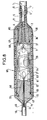
- La figure 2 représente une tête de câble selon l'invention avec armure dont le magasin de stockage est une boite à mou ; l'ensemble formé par la pièce de raccordement et le magasin de stockage doit être libre en translation dans la pièce d'ancrage, car si le câble subit une traction intempestive, l'armure va supporter cet effort. Le câble possède donc une possibilité de déplacement suffisante pour ne pas subir les effets de cette traction.
- La figure 3 représente une tête de câble selon l'invention sans armure dont le magasin de stockage est également une boite à mou : l'ensemble formé par la pièce de raccordement et le magasin de stockage est bloqué en translation dans la pièce d'ancrage.
- La figure 4 est une vue de détail des figures 2 et 3 représentant l'ensemble formé par la pièce de raccordement et le magasin de stockage qui dans ce cas est une boite à mou.
- La figure 5 représente les opérations de jonction des fibres optiques dans le cas de la figure 4.
- La figure 6 représente une variante selon l'invention, selon laquelle le câble dispose d'une armure et le magasin de stockage est un mandrin d'enroulement des fibres ; l'ensemble formé par la pièce de raccordement et le magasin de stockage doit être libre en translation dans la pièce d'ancrage, car si le câble subit une traction intempestive, l'armure va supporter cet effort. Le câble possède donc une possibilité de déplacement suffisante pour ne pas subir les effets de cette traction.
- La figure 7 représente une autre variante selon l'invention, selon laquelle le câble est sans armure, et le magasin de stockage est un mandrin d'enroulement ; l'ensemble formé par la pièce de raccordement et le magasin de stockage est bloqué en translation dans la pièce d'ancrage.
- La figure 8 est une vue agrandie de détail des figures 6 et 7 représentant l'ensemble formé par la pièce de raccordement et le magasin de stockage qui est, dans ce cas, un mandrin d'enroulement.
- La figure 9 représente une tête de câble sans armure dont la pièce de raccordement est bloquée en translation par une pièce de retenue, le magasin de stockage étant une boîte à mou située dans le répéteur.
- La figure 10 est une vue de détail de la figure 9 représentant la pièce de raccordement et le câble d'accès.
- Dans la figure 1, on voit un câble de la ligne 1, comportant un coeur optique 2 contenant les fibres optiques 3, une voûte en fils d'acier 4, un tube de cuivre 5 rétreint sur la voûte, une gaine isolante 6, en matière thermoplastique un conducteur de retour 7, une gaine de protection 8 en matière thermosplastique.
- Comme on le voit dans la figure 2, le câble 1 est protégé à l'extérieur d'une tête de câble 101 par une armure 9. Cette armure est maintenu en place sur un manchon de bourrage 13 par l'intermédiaire de frettes 10, et elle est fixée à une pièce d'ancrage 14 par des fourreaux 11 sertis. Des anodes de zinc 12 évitent la corrosion desdits fourreaux. Une boîte à mou 15 formé par une pièce de raccordement et un magasin de stockage, est libre en translation dans la pièce d'ancrage 14. Un tube gainé 16 sortant de l'ensemble 15, constitue le câble d'accès à un répéteur 17. Ce câble d'accès présente trois spires prévoyant un débattement axial et un renflement 50 de la gaine, qui protège un joint bateau décrit par la suite.
- Un cylindre de maintien 19 assure une meilleure rigidité de la pièce d'ancrage sur le boîtier de répéteur 18. La pièce d'ancrage est fixée sur ledit boîtier de répéteur par des boulons 21.
- Dans la figure 3 le câble 1 ne comporte pas d'armure, et à l'extrémité de la tête de câble 102 il est recouvert par un manchon de bourrage 30 qui empêche une trop grande flexion du câble. Ce manchon est vissé sur une pièce d'ancrage 31 au moyen d'un insert métallique 32. L'ensemble 15 est maintenu en translation dans la pièce d'ancrage 31, au moyen d'une pièce de retenue 33 elle-même fixée à la pièce d'ancrage par des vis 34. Le tube gainé 16 sortant de l'ensemble 15 constitue le câble d'accès d'un répéteur 17. Ce câble d'accès présente trois spires prévoyant un débattement axial et un renflement 50 de la gaine, qui protège un joint bateau décrit par la suite. La pièce d'ancrage est fixée sur le boîtier de répéteur 18 par des boulons 21.
- Dans la figure 4, la câble 1 est fixé à une pièce de raccordement 35 au moyen d'une bague conique 36 qui vient épanouir la voûte 4 de fils d'acier dans un=alésage de ladite pièce de raccordement 35.
- Un remplissage de fermeture 37 en résine durcissable solidifie la liaison de la voûte et de la pièce de raccordement. Une boite à mou 38 est vissée sur la pièce de raccordement et une étanchéité est prévue par l'intermédiaire de joints toriques 41, enfermés dans une pièce 40 qui est serrée au moyen d'une rondelle 39. Cette pièce 40 comporte un passage étanche 40' pour les fibres optiques. Un remplissage 49 en polyisobu- tylène est effectué à-travers deux orifices 49A et 49B fermés ultérieurement par deux bouchons. La rondelle 39 présente un épaulement 39' qui permet de lover les fibres optiques 3 environ au milieu de ladite boite 15 pour donner auxdites fibres un rayon de courbure maximum. Le tube gainé 16 est constitué ; d'un petit tube 42 pénétrant dans la boîte à mou 38 et soudé sur celle-ci ; d'une gaine isolante 43 en matière thermoplastique. La gaine isolante 6 du câble 1 et la gaine isolante 43 du tube 42 sont reconstituées par deux moulages de fermeture 46, 47 et par une gaine isolante 48. les deux moulages 46, 47 peuvent éventuellement être remplacés par un=moulage unique.
- Un conducteur de retour 44 et une gaine de protection 45 recouvrant la gaine 43 et l'ensemble 15 sont raccordés au conducteur de retour 7 et à la gaine de protection 8 du câble 1.
- Dans la figure 5 montrant les opérations de jonction des fibres optiques, on voit successivement l'opération A de soudure proprement dite des fibres 3 recouvertes au niveau de la soudure par un manchon 51, en B l'opération de remplissage de la boîte à mou, puis en C, le recouvrement du tube 16 par un joint bateau 52 et enfin le recouvrement de l'ensemble par une gaine 43 présentant un renflement 50 au niveau du joint bateau.
- Dans la figure 6 le câble 1 est protégé à l'extérieur de la tête de câble 103 par une armure 9.Cette armure est maintenu en place sur le manchon de bourrage 13 par l'intermédiaire de frettes 10, et elle est fixée à la pièce d'ancrage 14 par des fourreaux 11 sertis. Des anodes de zinc 12 évitent la corrosion desdits fourreaux. L'ensemble 60 formé par la pièce de raccordement et le magasin de stockage, est libre en translation dans la pièce d'ancrage 14. Un tube gainé 16 sortant de l'ensemble 60, constitue le câble d'accès à un répéteur 17. Ce câble d'accès présente trois spires prévoyant un débattement axial.
- Un cylindre de maintien 19 assure une meilleure rigidité de la pièce d'ancrage sur le boîtier de répéteur 18. La pièce d'ancrage est fixée sur ledit boîtier de répéteur par des boulons 21.
- Dans la figure 7, le câble 1 ne comporte pas d'armure et, à l'extrémité de la tête de câble 104 il est recouvert par un manchon de bourrage 53, qui empêche une trop grande flexion du câble. Ce manchon est vissé sur une pièce d'ancrage 54, au moyen de l'insert métallique 32. L'ensemble 60 est maintenu en translation dans la pièce d'ancrage 54 au moyen d'une pièce de retenue 56, toutes deux étant fixées au boîtier de répéteur 18, par des vis 55, un tube gainé 16 sortant de l'ensemble 60, constitue un câble d'accès à un répéteur 17. Ce câble d'accès présente trois spires prévoyant un débattement axial.
- Dans la figure 8, le câble 1 est fixé à une pièce de raccordement 58 au moyen de la bague conique 36 qui vient épanouir la voûte 4 de fils d'acier dans un alésage conique de ladite pièce de raccordement 58. Un remplissage de fermeture 37 en résine durcissable solidifie la liaison de la voûte et de la pièce de raccordement. Les fibres optiques 3,3' sont soudées l'une à l'autre, les soudures étant protégées par des manchons 59 ; elles sont ensuites enroulées sur un mandrin 61. Le tube 42 formant câble d'accès est engagé dans une pièce de raccordement 62 et soudé sur celle-ci. Un tube conteneur 63, préalablement enrobé d'une gaine isolante 64, est vissé sur les deux pièces de raccordement 58, 62 et des joints toniques 65, 66 assurent l'étanchéité. Les orifices 67, 68 servent au remplissage du mandrin par un produit visqueux tel que le polyisobuthylène. Une fois le remplissage terminé, ces orifices sont fermés par les bouchons 69, 70. La gaine isolante 6 du câble 1 et la gaine isolante 43 du tube 42 sont reconstituées par deux moulages de fermeture 71, 72 et par la gaine isolante 64 du tube conteneur 63. Un conducteur de retour 44 et une gaine de protection 45, recouvrant la gaine 43 et l'ensemble 15 sont raccordés au conducteur de retour 7 et à la gaine de protection 8 du câble 1.
- Dans la figure 9, le câble 1 est protégé à l'extérieur de la tête de câble 105 par un manchon de bourrage 82 vissé sur une pièce d'ancrage 81 au moyen d'un insert métallique 83. Le câble 1 est bloqué dans une pièce de raccordement 80, elle-même bloquée en translation dans la pièce d'ancrage 81 au moyen d'une pièce de retenue 85.
- Un surmoulage polyéthylène 86 entoure la pièce de raccordement 80.
- Des boulons 84 maintiennent la tête de câble 105 sur le boîtier du répéteur 18. Le magasin de stockage qui est dans ce cas une boite à mou 15 équivalente à la figure 4, est situé dans le répéteur 17. Le câble d'accès 16 présente trois spires prévoyant un débattement axial et un renflement 50 de la gaine, qui protège un joint bateau.
- Dans la figure 10, le câble 1 est fixé à la pièce de raccordement 80 au moyen d'une bague conique 36 qui vient épanouir la voûte 4 de fils d'acier dans un alésage conique de ladite pièce de raccordement 81. Un remplissage de fermeture 37 en résine durcissable solidifie la liaison de la voûte et de la pièce de raccordement. Le tube 42 reçoit les fibres optiques 3 et l'opération de jonction des fibres s'effectue suivant le procédé de la figure 5. Dès que le joint bateau 52 est mis en place, on recouvre le tube d'une gaine de protection 43 présentant un renflement 50. Le surmoulage polyéthylène 86 se raccorde à la gaine de protection 43 et à la gaine isolante 6 du câble 1. Un conducteur de retour et une gaine de protection, non représentés, enrobent le câble 1, le surmoulage 86 et la gaine de protection 43.
- Sans sortir du cadre de l'invention, le câble peut ne pas posséder de conducteur de retour protégé par une gaine de protection.
Claims (7)
Applications Claiming Priority (2)
| Application Number | Priority Date | Filing Date | Title |
|---|---|---|---|
| FR8204505 | 1982-03-17 | ||
| FR8204505A FR2523731A1 (fr) | 1982-03-17 | 1982-03-17 | Tete de cable pour cable immerge a fibre optiques |
Publications (3)
| Publication Number | Publication Date |
|---|---|
| EP0089057A2 true EP0089057A2 (fr) | 1983-09-21 |
| EP0089057A3 EP0089057A3 (en) | 1984-04-04 |
| EP0089057B1 EP0089057B1 (fr) | 1987-11-11 |
Family
ID=9272088
Family Applications (1)
| Application Number | Title | Priority Date | Filing Date |
|---|---|---|---|
| EP83102531A Expired EP0089057B1 (fr) | 1982-03-17 | 1983-03-15 | Tête de câble pour câble immergé à fibres optiques |
Country Status (6)
| Country | Link |
|---|---|
| US (1) | US4601536A (fr) |
| EP (1) | EP0089057B1 (fr) |
| JP (1) | JPS58172613A (fr) |
| DE (1) | DE3374442D1 (fr) |
| FR (1) | FR2523731A1 (fr) |
| NO (1) | NO166820C (fr) |
Cited By (11)
| Publication number | Priority date | Publication date | Assignee | Title |
|---|---|---|---|---|
| GB2138593A (en) * | 1983-04-23 | 1984-10-24 | Sumitomo Electric Industries | Handling Surplus Lengths of Optical Fibers at Cable Connection Points |
| FR2560455A1 (fr) * | 1984-02-25 | 1985-08-30 | Standard Telephones Cables Plc | Procede de fixation d'un cable sous-marin et cable sous-marin fixe a un recepteur |
| GB2159298A (en) * | 1984-05-25 | 1985-11-27 | Kokusai Denshin Denwa Co Ltd | Anchoring structure for optical submarine cable |
| FR2575558A1 (fr) * | 1984-12-28 | 1986-07-04 | Cables De Lyon Geoffroy Delore | Dispositif de raccordement d'un cable a fibres optiques a un boitier de jonction |
| FR2585139A1 (fr) * | 1985-07-17 | 1987-01-23 | Lignes Telegraph Telephon | Tete d'eclatement d'un cable a fibres optiques en faisceaux de fibres ou en fibres |
| GB2191604A (en) * | 1987-07-07 | 1987-12-16 | Stc Plc | Optical repeater having resilient coiled optical fibre carrier |
| GB2194700A (en) * | 1986-08-28 | 1988-03-09 | Stc Plc | Optical repeaters |
| FR2606963A1 (fr) * | 1986-11-14 | 1988-05-20 | Cit Alcatel | Boitier de repeteur sous-marin |
| EP0142379B1 (fr) * | 1983-11-17 | 1989-11-29 | BRITISH TELECOMMUNICATIONS public limited company | Dispositifs de couplage |
| EP0274192A3 (fr) * | 1987-01-09 | 1990-05-16 | AT&T Corp. | Ancrage d'une fibre optique dans un manchon sur jonction épissée |
| FR2738924A1 (fr) * | 1995-09-18 | 1997-03-21 | Cortaillod Cables Sa | Embout de terminaison d'un cable optique |
Families Citing this family (29)
| Publication number | Priority date | Publication date | Assignee | Title |
|---|---|---|---|---|
| GB2128357B (en) * | 1982-10-06 | 1986-05-21 | Standard Telephones Cables Ltd | Optical fibre cables |
| FR2573543B1 (fr) * | 1984-11-16 | 1986-12-19 | Cables De Lyon Geoffroy Delore | Dispositif de raccordement d'un cable a fibres optiques a un boitier de jonction, et procede de fabrication de ce dispositif |
| US4733935A (en) * | 1985-02-08 | 1988-03-29 | The Rochester Corporation | Symmetrical connector for optical fiber cables in a hostile environment |
| US4711520A (en) * | 1985-07-02 | 1987-12-08 | Litton Systems, Inc. | Fiber optic connector backshell |
| JPH0423205Y2 (fr) * | 1985-08-20 | 1992-05-29 | ||
| GB8602425D0 (en) * | 1986-01-31 | 1986-03-05 | Raychem Sa Nv | Optical fibre splice case |
| DE3630659A1 (de) * | 1986-09-09 | 1988-03-17 | Philips Patentverwaltung | Abzweig fuer ein mehrere lwl enthaltendes optisches kabel und verfahren zu seiner herstellung |
| FR2606944B1 (fr) * | 1986-11-14 | 1989-01-13 | Cables De Lyon Geoffroy Delore | Tete articulee de cable pour liaisons sous-marines |
| US4738505A (en) * | 1986-12-04 | 1988-04-19 | RCA Corporate | Fiber optic cable termination |
| JPH0746163B2 (ja) * | 1986-12-05 | 1995-05-17 | 古河電気工業株式会社 | 電力・光複合ケ−ブルの光ケ−ブル接続部 |
| FR2607939B1 (fr) * | 1986-12-05 | 1989-02-03 | Cables De Lyon Geoffroy Delore | Boite de raccordement pour cables a fibres optiques |
| DE3732024A1 (de) * | 1987-09-23 | 1989-04-06 | Rheydt Kabelwerk Ag | Muffe fuer lichtwellenleiterkabel |
| US4846545A (en) * | 1988-03-30 | 1989-07-11 | The United States Of America As Represented By The Secretary Of The Navy | Fiber optic cable connection |
| GB2217871A (en) * | 1988-04-28 | 1989-11-01 | Stc Plc | Optical fibre seals in walls of a chamber |
| GB2229545B (en) * | 1989-03-21 | 1993-04-28 | Stc Plc | Jointing optical fibre cables |
| US5082338A (en) * | 1989-12-01 | 1992-01-21 | Ron Hodge | Fiber optic conduit-connector assembly |
| FR2676316B1 (fr) * | 1991-05-07 | 1993-07-16 | Alcatel Cable | Cable d'acces de repeteur sous-marin. |
| GB2256285B (en) * | 1991-06-01 | 1995-02-01 | Northern Telecom Ltd | Underwater cable joints |
| GB2264789A (en) * | 1992-02-25 | 1993-09-08 | Northern Telecom Ltd | Submarine optical repeater tail tube termination using tangential screw |
| GB2272114A (en) * | 1992-10-27 | 1994-05-04 | Northern Telecom Ltd | Tacking tensile load at cable joints |
| AU735821B2 (en) * | 1996-10-10 | 2001-07-19 | Tyco Submarine Systems Ltd. | Submarine optical cable joint with terminating sockets |
| US5982971A (en) * | 1996-10-10 | 1999-11-09 | Tyco Submarine Systems Ltd. | Floating fiber storage assembly |
| DE69738402T2 (de) * | 1996-10-10 | 2008-07-03 | Tyco Telecommunications (Us) Inc. | Unterseewasserverbinder vom faseroptischen kabel mit lasttragendem gehäuse |
| US6733185B2 (en) * | 2002-08-12 | 2004-05-11 | Hon Hai Precision Ind. Co., Ltd. | Optical fiber connector assembly having fiber saver |
| EP1675241A1 (fr) * | 2004-12-23 | 2006-06-28 | MAN Turbomaschinen AG Schweiz | Traversée de câbles étanche |
| US8328431B2 (en) * | 2010-02-01 | 2012-12-11 | Tyco Electronics Subsea Communications Llc | Coupling multiple conductor undersea optical cables to an undersea device with an isolated bypass conductive path across the undersea device |
| JP6736870B2 (ja) * | 2015-11-26 | 2020-08-05 | 住友電装株式会社 | 導電路 |
| DE102016103955A1 (de) * | 2016-03-04 | 2017-09-07 | Atlas Elektronik Gmbh | Unterwasserstecker für ein Unterwasserfahrzeug sowie ein Verfahren damit und Unterwasserfahrzeug |
| USD828861S1 (en) | 2016-04-13 | 2018-09-18 | Global Marine Systems Limited | Fiber optic joint |
Family Cites Families (17)
| Publication number | Priority date | Publication date | Assignee | Title |
|---|---|---|---|---|
| US4107451A (en) * | 1975-11-19 | 1978-08-15 | Trech, Inc. | Reinforced splice joint and method of making same |
| FR2363243A1 (fr) * | 1976-08-24 | 1978-03-24 | Cit Alcatel | Liaison a distance par cables optiques |
| GB2025650B (en) * | 1978-07-18 | 1982-08-18 | Standard Telephones Cables Ltd | Fibre-optic cable joints |
| FR2433189A1 (fr) * | 1978-08-11 | 1980-03-07 | Cit Alcatel | Dispositif de raccordement etanche d'un cable a fibres optiques a un boitier immerge |
| JPS5922203B2 (ja) * | 1978-10-06 | 1984-05-25 | ケイディディ株式会社 | 光海底中継器のフイ−ドスル |
| NL7900432A (nl) * | 1979-01-19 | 1980-07-22 | Nkf Groep Bv | Glasvezel verbindingsmof. |
| GB2043943B (en) * | 1979-02-27 | 1982-12-08 | Plessey Co Ltd | Optical cable gland |
| JPS5685716A (en) * | 1979-12-14 | 1981-07-13 | Nippon Telegr & Teleph Corp <Ntt> | Connector in submarine optical repeater |
| DE3006131C2 (de) * | 1980-02-19 | 1983-04-28 | AEG-Telefunken Nachrichtentechnik GmbH, 7150 Backnang | Spleißmuffe mit einer Aufnahmevorrichtung für Vorratslängen von Lichtwellenleiterkabeln |
| JPS56158313A (en) * | 1980-05-12 | 1981-12-07 | Kokusai Denshin Denwa Co Ltd <Kdd> | Sealing structure at lead-in part of optical fiber cable |
| JPS5719705A (en) * | 1980-07-09 | 1982-02-02 | Fujitsu Ltd | Optical submarine repeater |
| JPS5719706A (en) * | 1980-07-10 | 1982-02-02 | Fujitsu Ltd | Optical submarine repeater |
| US4317000A (en) * | 1980-07-23 | 1982-02-23 | The United States Of America As Represented By The Secretary Of The Navy | Contrahelically laid torque balanced benthic cable |
| JPS5737315A (en) * | 1980-08-18 | 1982-03-01 | Nippon Telegr & Teleph Corp <Ntt> | Connection part of submarine optical cable |
| JPS5773710A (en) * | 1980-10-27 | 1982-05-08 | Nippon Telegr & Teleph Corp <Ntt> | Submarine optical cable connection part |
| JPS6011321B2 (ja) * | 1981-01-20 | 1985-03-25 | ケイディディ株式会社 | 光海底中継器の光フアイバ接続部収容構造 |
| FR2505569A1 (fr) * | 1981-05-07 | 1982-11-12 | Cables De Lyon Geoffroy Delore | Jonction multiple pour systeme sous-marin |
-
1982
- 1982-03-17 FR FR8204505A patent/FR2523731A1/fr active Granted
-
1983
- 1983-03-11 NO NO830855A patent/NO166820C/no unknown
- 1983-03-15 EP EP83102531A patent/EP0089057B1/fr not_active Expired
- 1983-03-15 US US06/475,561 patent/US4601536A/en not_active Expired - Fee Related
- 1983-03-15 DE DE8383102531T patent/DE3374442D1/de not_active Expired
- 1983-03-16 JP JP58044040A patent/JPS58172613A/ja active Pending
Cited By (15)
| Publication number | Priority date | Publication date | Assignee | Title |
|---|---|---|---|---|
| GB2138593A (en) * | 1983-04-23 | 1984-10-24 | Sumitomo Electric Industries | Handling Surplus Lengths of Optical Fibers at Cable Connection Points |
| EP0142379B1 (fr) * | 1983-11-17 | 1989-11-29 | BRITISH TELECOMMUNICATIONS public limited company | Dispositifs de couplage |
| US4621167A (en) * | 1984-02-25 | 1986-11-04 | Standard Telephones And Cables Public Limited Company | Submarine cable anchored to a repeater housing and method of assembly thereof |
| FR2560455A1 (fr) * | 1984-02-25 | 1985-08-30 | Standard Telephones Cables Plc | Procede de fixation d'un cable sous-marin et cable sous-marin fixe a un recepteur |
| GB2155195A (en) * | 1984-02-25 | 1985-09-18 | Standard Telephones Cables Ltd | Anchoring light weight submarine cable |
| GB2159298A (en) * | 1984-05-25 | 1985-11-27 | Kokusai Denshin Denwa Co Ltd | Anchoring structure for optical submarine cable |
| EP0187368A1 (fr) * | 1984-12-28 | 1986-07-16 | LES CABLES DE LYON Société anonyme dite: | Dispositif de raccordement d'un câble à fibres optiques à un boîtier de jonction |
| FR2575558A1 (fr) * | 1984-12-28 | 1986-07-04 | Cables De Lyon Geoffroy Delore | Dispositif de raccordement d'un cable a fibres optiques a un boitier de jonction |
| FR2585139A1 (fr) * | 1985-07-17 | 1987-01-23 | Lignes Telegraph Telephon | Tete d'eclatement d'un cable a fibres optiques en faisceaux de fibres ou en fibres |
| GB2194700A (en) * | 1986-08-28 | 1988-03-09 | Stc Plc | Optical repeaters |
| GB2194700B (en) * | 1986-08-28 | 1991-04-17 | Stc Plc | Optical repeaters |
| FR2606963A1 (fr) * | 1986-11-14 | 1988-05-20 | Cit Alcatel | Boitier de repeteur sous-marin |
| EP0274192A3 (fr) * | 1987-01-09 | 1990-05-16 | AT&T Corp. | Ancrage d'une fibre optique dans un manchon sur jonction épissée |
| GB2191604A (en) * | 1987-07-07 | 1987-12-16 | Stc Plc | Optical repeater having resilient coiled optical fibre carrier |
| FR2738924A1 (fr) * | 1995-09-18 | 1997-03-21 | Cortaillod Cables Sa | Embout de terminaison d'un cable optique |
Also Published As
| Publication number | Publication date |
|---|---|
| NO830855L (no) | 1983-09-19 |
| JPS58172613A (ja) | 1983-10-11 |
| DE3374442D1 (en) | 1987-12-17 |
| NO166820B (no) | 1991-05-27 |
| FR2523731A1 (fr) | 1983-09-23 |
| NO166820C (no) | 1991-09-04 |
| EP0089057B1 (fr) | 1987-11-11 |
| US4601536A (en) | 1986-07-22 |
| EP0089057A3 (en) | 1984-04-04 |
| FR2523731B1 (fr) | 1984-11-09 |
Similar Documents
| Publication | Publication Date | Title |
|---|---|---|
| EP0089057B1 (fr) | Tête de câble pour câble immergé à fibres optiques | |
| EP0066829B1 (fr) | Dispositif de jonction des extrémités de deux câbles sous-marins à fibres optiques et procédé de montage d'un tel dispositif | |
| EP0083101A2 (fr) | Dispositif de jonction des extrémités de deux câbles sous-marins à fibres optiques, et son procédé de fabrication | |
| EP0138035B1 (fr) | Dispositif de raccordement entre un câble immergé à fibres optiques et un répéteur | |
| EP0138052B1 (fr) | Boîte de jonction pour le raccordement par soudre des extrémités de deux cables sous-marins à fibres optiques | |
| EP0133873A1 (fr) | Câble sous-marin à fibres optiques et procédé de fabrication d'un tel câble | |
| FR2568737A1 (fr) | Ligne sous-marine pour telecommunications a fibres optiques | |
| FR2549969A1 (fr) | Procede d'injection d'un produit de remplissage visqueux dans les rainures de logement des fibres optiques d'un jonc, et dispositif de mise en oeuvre de ce procede | |
| CA1290603C (fr) | Dispositif d'etancheite longitudinale pour l'ame d'un cable optique | |
| EP0347823B1 (fr) | Dispositif de jonction des armures de deux câbles armés par des fils, et procédé de fabrication de ce dispositif | |
| FR2769419A1 (fr) | Dispositif de protection etanche pour une jonction de cables haute tension | |
| EP0512486B1 (fr) | Câble d'accès de répéteur sous-marin | |
| EP0129184B1 (fr) | Jonction multiple pour câbles sous-marins à fibres optiques | |
| CA1282129C (fr) | Jonction souple pour cable sous-marin au papier impregne | |
| AU664285B2 (en) | Splicing box for submarine cable | |
| EP0432682A1 (fr) | Dispositif d'étanchéité longitudinale pour l'âme d'un câble optique | |
| EP0469502B1 (fr) | Dispositif rupteur mécanique pour câble d'accès à un boîtier d'équipements immergé | |
| EP1388190B1 (fr) | Dispositif d'etancheite pour le passage d'un cable a travers une paroi d'une conduite sous pression | |
| FR2594561A1 (fr) | Dispositif de renforcement de la partie interne de cables sismiques | |
| FR2493057A1 (fr) | Dispositif de raccordement electrique etanche entre un cable sous-marin telephonique et un repeteur | |
| CH321638A (fr) | Connexion flexible pour fluide sous pression | |
| US2414352A (en) | Joint for electric cables | |
| EP0513733A1 (fr) | Dispositif d'ancrage de câble de garde | |
| FR2926166A1 (fr) | Kit de capteurs de temperature, notamment pour turbine a combustion. | |
| CH588176A5 (en) | Watertight joint for low voltage electric cables - has gas filled bellows pressurising reservoir of dielectric surrounding joint |
Legal Events
| Date | Code | Title | Description |
|---|---|---|---|
| PUAI | Public reference made under article 153(3) epc to a published international application that has entered the european phase |
Free format text: ORIGINAL CODE: 0009012 |
|
| AK | Designated contracting states |
Designated state(s): DE FR GB IT |
|
| PUAL | Search report despatched |
Free format text: ORIGINAL CODE: 0009013 |
|
| AK | Designated contracting states |
Designated state(s): DE FR GB IT |
|
| 17P | Request for examination filed |
Effective date: 19840925 |
|
| 17Q | First examination report despatched |
Effective date: 19860421 |
|
| GRAA | (expected) grant |
Free format text: ORIGINAL CODE: 0009210 |
|
| AK | Designated contracting states |
Kind code of ref document: B1 Designated state(s): DE FR GB IT |
|
| REF | Corresponds to: |
Ref document number: 3374442 Country of ref document: DE Date of ref document: 19871217 |
|
| GBT | Gb: translation of ep patent filed (gb section 77(6)(a)/1977) | ||
| ITF | It: translation for a ep patent filed | ||
| PLBE | No opposition filed within time limit |
Free format text: ORIGINAL CODE: 0009261 |
|
| STAA | Information on the status of an ep patent application or granted ep patent |
Free format text: STATUS: NO OPPOSITION FILED WITHIN TIME LIMIT |
|
| 26N | No opposition filed | ||
| ITTA | It: last paid annual fee | ||
| PGFP | Annual fee paid to national office [announced via postgrant information from national office to epo] |
Ref country code: DE Payment date: 19950221 Year of fee payment: 13 |
|
| PG25 | Lapsed in a contracting state [announced via postgrant information from national office to epo] |
Ref country code: DE Effective date: 19961203 |
|
| PGFP | Annual fee paid to national office [announced via postgrant information from national office to epo] |
Ref country code: GB Payment date: 19970213 Year of fee payment: 15 |
|
| PGFP | Annual fee paid to national office [announced via postgrant information from national office to epo] |
Ref country code: FR Payment date: 19970214 Year of fee payment: 15 |
|
| PG25 | Lapsed in a contracting state [announced via postgrant information from national office to epo] |
Ref country code: GB Free format text: LAPSE BECAUSE OF NON-PAYMENT OF DUE FEES Effective date: 19980315 |
|
| PG25 | Lapsed in a contracting state [announced via postgrant information from national office to epo] |
Ref country code: FR Free format text: THE PATENT HAS BEEN ANNULLED BY A DECISION OF A NATIONAL AUTHORITY Effective date: 19980331 |
|
| GBPC | Gb: european patent ceased through non-payment of renewal fee |
Effective date: 19980315 |
|
| REG | Reference to a national code |
Ref country code: FR Ref legal event code: ST |