EP0089081A1 - Système hydraulique de freinage pour véhicules - Google Patents
Système hydraulique de freinage pour véhicules Download PDFInfo
- Publication number
- EP0089081A1 EP0089081A1 EP83200313A EP83200313A EP0089081A1 EP 0089081 A1 EP0089081 A1 EP 0089081A1 EP 83200313 A EP83200313 A EP 83200313A EP 83200313 A EP83200313 A EP 83200313A EP 0089081 A1 EP0089081 A1 EP 0089081A1
- Authority
- EP
- European Patent Office
- Prior art keywords
- pressure
- brake
- hydraulic
- motor
- pump
- Prior art date
- Legal status (The legal status is an assumption and is not a legal conclusion. Google has not performed a legal analysis and makes no representation as to the accuracy of the status listed.)
- Withdrawn
Links
Images


Classifications
-
- B—PERFORMING OPERATIONS; TRANSPORTING
- B60—VEHICLES IN GENERAL
- B60T—VEHICLE BRAKE CONTROL SYSTEMS OR PARTS THEREOF; BRAKE CONTROL SYSTEMS OR PARTS THEREOF, IN GENERAL; ARRANGEMENT OF BRAKING ELEMENTS ON VEHICLES IN GENERAL; PORTABLE DEVICES FOR PREVENTING UNWANTED MOVEMENT OF VEHICLES; VEHICLE MODIFICATIONS TO FACILITATE COOLING OF BRAKES
- B60T13/00—Transmitting braking action from initiating means to ultimate brake actuator with power assistance or drive; Brake systems incorporating such transmitting means, e.g. air-pressure brake systems
- B60T13/10—Transmitting braking action from initiating means to ultimate brake actuator with power assistance or drive; Brake systems incorporating such transmitting means, e.g. air-pressure brake systems with fluid assistance, drive, or release
- B60T13/66—Electrical control in fluid-pressure brake systems
- B60T13/665—Electrical control in fluid-pressure brake systems the systems being specially adapted for transferring two or more command signals, e.g. railway systems
-
- B—PERFORMING OPERATIONS; TRANSPORTING
- B60—VEHICLES IN GENERAL
- B60T—VEHICLE BRAKE CONTROL SYSTEMS OR PARTS THEREOF; BRAKE CONTROL SYSTEMS OR PARTS THEREOF, IN GENERAL; ARRANGEMENT OF BRAKING ELEMENTS ON VEHICLES IN GENERAL; PORTABLE DEVICES FOR PREVENTING UNWANTED MOVEMENT OF VEHICLES; VEHICLE MODIFICATIONS TO FACILITATE COOLING OF BRAKES
- B60T13/00—Transmitting braking action from initiating means to ultimate brake actuator with power assistance or drive; Brake systems incorporating such transmitting means, e.g. air-pressure brake systems
- B60T13/10—Transmitting braking action from initiating means to ultimate brake actuator with power assistance or drive; Brake systems incorporating such transmitting means, e.g. air-pressure brake systems with fluid assistance, drive, or release
- B60T13/12—Transmitting braking action from initiating means to ultimate brake actuator with power assistance or drive; Brake systems incorporating such transmitting means, e.g. air-pressure brake systems with fluid assistance, drive, or release the fluid being liquid
- B60T13/22—Brakes applied by springs or weights and released hydraulically
-
- B—PERFORMING OPERATIONS; TRANSPORTING
- B60—VEHICLES IN GENERAL
- B60T—VEHICLE BRAKE CONTROL SYSTEMS OR PARTS THEREOF; BRAKE CONTROL SYSTEMS OR PARTS THEREOF, IN GENERAL; ARRANGEMENT OF BRAKING ELEMENTS ON VEHICLES IN GENERAL; PORTABLE DEVICES FOR PREVENTING UNWANTED MOVEMENT OF VEHICLES; VEHICLE MODIFICATIONS TO FACILITATE COOLING OF BRAKES
- B60T13/00—Transmitting braking action from initiating means to ultimate brake actuator with power assistance or drive; Brake systems incorporating such transmitting means, e.g. air-pressure brake systems
- B60T13/10—Transmitting braking action from initiating means to ultimate brake actuator with power assistance or drive; Brake systems incorporating such transmitting means, e.g. air-pressure brake systems with fluid assistance, drive, or release
- B60T13/58—Combined or convertible systems
Definitions
- the invention relates to a hydraulic brake system for vehicles, particularly light rail vehicles such as trams, including at least one brake actuator and a pump unit for the supply of hydraulic fluid to said brake actuator, comprising a pump and an electric drive motor connected therewith.
- the purpose of the invention is to provide a brake system for vehicles which is simple, flexible, fast and reliable.
- a brake system for vehicles which can be easily controlled and is suitable for integration with the traction system of the vehicle, has a low power consumption and a low noise level and is of a compact low-weight design.
- the invention provides a hydraulic brake system for vehicles of the type referred to above which is characterized by electronic means controlling the rotational speed of the drive motor in dependence on the required braking force to be supplied by the actuator.
- Two emergency levels can be foreseen in the vehicle brake system described, viz. a first level obtained when the driver releases the safety pedal or de-activates a corresponding switch and a second level which is obtained when the emergency switch 12' connected to the controller 11 is activated.
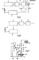
- the system can be set under pressure so as to release the brakes by adjusting the valve 28 to the position in which conduits 19 and 22 are interconnected at one hand and conduits 19' and 22' are interconnected at the other hand, conduits 19" and 22" accordingly also being interconnected, and by supplying hydraulic fluid under pressure by a hand pump to conduit 19' at the connection 30.
- the fluid is conveyed to the calipers 39 via valve 28 and conduits 22', 22", valves 36, 36F and 36R opening under the fluid pressure.
- valve 46 is provided having two solenoids 47A and 47B. In the position shown, valve 46 provides a connection of conduit 22 to tank 10 through restrictor 44.
- solenoid 47A When solenoid 47A is energized the valve provides a connection between conduit 22 and tank 10 through restrictor 45, and when solenoid 47B is energized the valve provides a direct connection from conduit 22 to tank 10 without any restriction of the hydraulic flow.
- the disc brake caliper 39 When the brake system of Fig. 7 is de-energized the disc brake caliper 39 is connected to the tank 10 via the restrictor 44, and the brake is applied with the maximum braking force under the spring bias of the disc brake caliper.
- the vehicle is brought to standstill at a stopping place by reducing the motor current to the minimum value, and at standstill the solenoid 47B of the valve 46 is energized and the motor is operated at a limited rotational speed in order to collect contaminants, if any, in the filter 43.
- the torque provided by the motor will disappear.
- the hydraulic pressure in the system which previously balanced the torque, then will accelerate the pump in the opposite rotational direction, i.e. the pump will operate as a motor until the hydraulic pressure of the system reaches zero.
- the check valve 42 allows hydraulic fluid to be sucked through the pump at continued rotation of the motor pump system in order to prevent the creation of a vacuum in the system.
Landscapes
- Engineering & Computer Science (AREA)
- Transportation (AREA)
- Mechanical Engineering (AREA)
- Regulating Braking Force (AREA)
- Valves And Accessory Devices For Braking Systems (AREA)
- Braking Arrangements (AREA)
Applications Claiming Priority (2)
| Application Number | Priority Date | Filing Date | Title |
|---|---|---|---|
| SE8201638 | 1982-03-16 | ||
| SE8201638A SE440891B (sv) | 1982-03-16 | 1982-03-16 | Hydrauliskt bromssystem for fordon, serskilt letta jernvegsfordon |
Publications (1)
| Publication Number | Publication Date |
|---|---|
| EP0089081A1 true EP0089081A1 (fr) | 1983-09-21 |
Family
ID=20346269
Family Applications (1)
| Application Number | Title | Priority Date | Filing Date |
|---|---|---|---|
| EP83200313A Withdrawn EP0089081A1 (fr) | 1982-03-16 | 1983-03-07 | Système hydraulique de freinage pour véhicules |
Country Status (8)
| Country | Link |
|---|---|
| EP (1) | EP0089081A1 (fr) |
| JP (1) | JPS58164465A (fr) |
| AU (1) | AU552552B2 (fr) |
| BR (1) | BR8301266A (fr) |
| FI (1) | FI830837L (fr) |
| HU (1) | HUH2975A (fr) |
| SE (1) | SE440891B (fr) |
| ZA (1) | ZA831766B (fr) |
Cited By (5)
| Publication number | Priority date | Publication date | Assignee | Title |
|---|---|---|---|---|
| EP0200632A1 (fr) * | 1985-04-22 | 1986-11-05 | Régie Autonome des Transports Parisiens RATP | Système de freinage hydraulique pour véhicules ferroviaires |
| US10106137B2 (en) | 2017-01-06 | 2018-10-23 | Ford Global Technologies, Llc | Adjustment of maximum brake pump speed based on rate of change of target deceleration |
| US10300899B2 (en) * | 2017-01-06 | 2019-05-28 | Ford Global Technologies, Llc | Adjustment of maximum brake pump speed based on rate of change of target deceleration |
| WO2019197453A1 (fr) * | 2018-04-11 | 2019-10-17 | Siemens Ag Österreich | Dispositif de desserrage d'urgence pour un frein à ressort d'un véhicule ferroviaire |
| CN118220086A (zh) * | 2023-12-28 | 2024-06-21 | 比亚迪股份有限公司 | 液压制动系统及车辆 |
Citations (9)
| Publication number | Priority date | Publication date | Assignee | Title |
|---|---|---|---|---|
| US1856635A (en) * | 1930-06-19 | 1932-05-03 | Earl R Herren | Mechanically operated brake |
| US2330739A (en) * | 1940-11-29 | 1943-09-28 | Transit Res Corp | Hydraulic braking system |
| US2336887A (en) * | 1940-11-29 | 1943-12-14 | Transit Res Corp | Pressure regulating valve for hydraulic brakes |
| GB613420A (en) * | 1943-11-13 | 1948-11-29 | Clark Equipment Co | Improvements in or relating to brake applying mechanism |
| US3350142A (en) * | 1965-02-08 | 1967-10-31 | Midland Ross Corp | Actuator system |
| FR2210532A1 (fr) * | 1972-12-13 | 1974-07-12 | Girling Ltd | |
| US3951464A (en) * | 1974-08-30 | 1976-04-20 | Donahue James C | Truck-trailer brake system with independent control of trailer brakes |
| US4094553A (en) * | 1977-07-28 | 1978-06-13 | General Signal Corporation | Brake control system having an electro-pneumatic pilot valve |
| GB1587405A (en) * | 1977-07-18 | 1981-04-01 | Dilltown Holdings Ltd | Braking systems |
-
1982
- 1982-03-16 SE SE8201638A patent/SE440891B/sv not_active IP Right Cessation
-
1983
- 1983-03-07 EP EP83200313A patent/EP0089081A1/fr not_active Withdrawn
- 1983-03-14 BR BR8301266A patent/BR8301266A/pt unknown
- 1983-03-14 FI FI830837A patent/FI830837L/fi not_active Application Discontinuation
- 1983-03-15 AU AU12471/83A patent/AU552552B2/en not_active Ceased
- 1983-03-15 ZA ZA831766A patent/ZA831766B/xx unknown
- 1983-03-16 HU HU83895A patent/HUH2975A/hu unknown
- 1983-03-16 JP JP58042476A patent/JPS58164465A/ja active Pending
Patent Citations (9)
| Publication number | Priority date | Publication date | Assignee | Title |
|---|---|---|---|---|
| US1856635A (en) * | 1930-06-19 | 1932-05-03 | Earl R Herren | Mechanically operated brake |
| US2330739A (en) * | 1940-11-29 | 1943-09-28 | Transit Res Corp | Hydraulic braking system |
| US2336887A (en) * | 1940-11-29 | 1943-12-14 | Transit Res Corp | Pressure regulating valve for hydraulic brakes |
| GB613420A (en) * | 1943-11-13 | 1948-11-29 | Clark Equipment Co | Improvements in or relating to brake applying mechanism |
| US3350142A (en) * | 1965-02-08 | 1967-10-31 | Midland Ross Corp | Actuator system |
| FR2210532A1 (fr) * | 1972-12-13 | 1974-07-12 | Girling Ltd | |
| US3951464A (en) * | 1974-08-30 | 1976-04-20 | Donahue James C | Truck-trailer brake system with independent control of trailer brakes |
| GB1587405A (en) * | 1977-07-18 | 1981-04-01 | Dilltown Holdings Ltd | Braking systems |
| US4094553A (en) * | 1977-07-28 | 1978-06-13 | General Signal Corporation | Brake control system having an electro-pneumatic pilot valve |
Cited By (7)
| Publication number | Priority date | Publication date | Assignee | Title |
|---|---|---|---|---|
| EP0200632A1 (fr) * | 1985-04-22 | 1986-11-05 | Régie Autonome des Transports Parisiens RATP | Système de freinage hydraulique pour véhicules ferroviaires |
| US10106137B2 (en) | 2017-01-06 | 2018-10-23 | Ford Global Technologies, Llc | Adjustment of maximum brake pump speed based on rate of change of target deceleration |
| US10300899B2 (en) * | 2017-01-06 | 2019-05-28 | Ford Global Technologies, Llc | Adjustment of maximum brake pump speed based on rate of change of target deceleration |
| WO2019197453A1 (fr) * | 2018-04-11 | 2019-10-17 | Siemens Ag Österreich | Dispositif de desserrage d'urgence pour un frein à ressort d'un véhicule ferroviaire |
| CN112041209A (zh) * | 2018-04-11 | 2020-12-04 | 西门子交通奥地利有限责任公司 | 用于轨道车辆的弹簧储能式制动器的紧急释放装置 |
| CN112041209B (zh) * | 2018-04-11 | 2022-10-11 | 西门子交通奥地利有限责任公司 | 用于轨道车辆的弹簧储能式制动器的紧急释放装置 |
| CN118220086A (zh) * | 2023-12-28 | 2024-06-21 | 比亚迪股份有限公司 | 液压制动系统及车辆 |
Also Published As
| Publication number | Publication date |
|---|---|
| FI830837A7 (fi) | 1983-09-17 |
| FI830837A0 (fi) | 1983-03-14 |
| AU1247183A (en) | 1983-09-22 |
| FI830837L (fi) | 1983-09-17 |
| ZA831766B (en) | 1983-11-30 |
| BR8301266A (pt) | 1983-11-22 |
| SE8201638L (sv) | 1983-09-17 |
| SE440891B (sv) | 1985-08-26 |
| JPS58164465A (ja) | 1983-09-29 |
| AU552552B2 (en) | 1986-06-05 |
| HUH2975A (en) | 1985-07-29 |
Similar Documents
| Publication | Publication Date | Title |
|---|---|---|
| US4565411A (en) | Hydraulic brake system with slip control | |
| US8083041B2 (en) | Electrohydraulic torque transfer device | |
| US9925964B2 (en) | Vehicle braking unit and method | |
| US6082830A (en) | Brake system having variable pump pressure control and method of pressure control | |
| US5709438A (en) | Failed booster back-up braking system | |
| EP0280740B1 (fr) | Systeme de regulation de la pression de freinage | |
| US9611906B2 (en) | Hydraulic vehicle clutch system and method | |
| US20090032360A1 (en) | Hydraulic Vehicle Clutch System and Method | |
| US5195810A (en) | Anti-lock hydraulic brake system | |
| GB2229238A (en) | Vehicle anti-lock brake systems | |
| JPS59199352A (ja) | 自動車用ブレ−キ装置 | |
| US6991303B2 (en) | Hydraulic braking system operated by an external force | |
| GB2253254A (en) | Hydraulic braking system | |
| JPS6346958A (ja) | スリップ制御ブレ−キシステム | |
| CZ286436B6 (en) | Operation process of motor vehicle brake mechanism with protection against blocking | |
| JPH02169357A (ja) | トラクションスリップコントロール及び/又は(登坂)発進補助コントロールを実施するための装置 | |
| US5609401A (en) | Proportional braking system with dual poppet valves | |
| JPH04260853A (ja) | スキッドコントロールされる油圧式多回路ブレーキ装置 | |
| US5190358A (en) | Antilock brake system for providing different brake pressures to front and rear wheel circuits | |
| JPS63242756A (ja) | ロツキング防止手段を備えた車両の液圧ブレーキ装置 | |
| EP0089081A1 (fr) | Système hydraulique de freinage pour véhicules | |
| JPH0558263A (ja) | ブレーキスリツプ及びトラクシヨンスリツプ用コントロール装置付油圧式ブレーキシステム | |
| US4181368A (en) | Hydraulic vehicle brake system | |
| US10576953B2 (en) | Electronically slip-controllable braking system | |
| JPH07506551A (ja) | スリップ制御付き液圧ブレーキシステム |
Legal Events
| Date | Code | Title | Description |
|---|---|---|---|
| PUAI | Public reference made under article 153(3) epc to a published international application that has entered the european phase |
Free format text: ORIGINAL CODE: 0009012 |
|
| AK | Designated contracting states |
Designated state(s): AT BE CH DE FR GB IT LI NL SE |
|
| 17P | Request for examination filed |
Effective date: 19840109 |
|
| STAA | Information on the status of an ep patent application or granted ep patent |
Free format text: STATUS: THE APPLICATION IS DEEMED TO BE WITHDRAWN |
|
| 18D | Application deemed to be withdrawn |
Effective date: 19860819 |
|
| RIN1 | Information on inventor provided before grant (corrected) |
Inventor name: HARSTROEM, JAN-OLA |