EP0089736B1 - Informationsspur-Zentriersystem - Google Patents
Informationsspur-Zentriersystem Download PDFInfo
- Publication number
- EP0089736B1 EP0089736B1 EP83300506A EP83300506A EP0089736B1 EP 0089736 B1 EP0089736 B1 EP 0089736B1 EP 83300506 A EP83300506 A EP 83300506A EP 83300506 A EP83300506 A EP 83300506A EP 0089736 B1 EP0089736 B1 EP 0089736B1
- Authority
- EP
- European Patent Office
- Prior art keywords
- order
- order radiation
- information track
- generating
- beams
- Prior art date
- Legal status (The legal status is an assumption and is not a legal conclusion. Google has not performed a legal analysis and makes no representation as to the accuracy of the status listed.)
- Expired
Links
- 230000005855 radiation Effects 0.000 claims description 60
- 230000003287 optical effect Effects 0.000 claims description 41
- 230000001360 synchronised effect Effects 0.000 claims description 8
- 230000010355 oscillation Effects 0.000 claims description 7
- 238000001514 detection method Methods 0.000 claims description 5
- 238000001228 spectrum Methods 0.000 claims description 3
- 230000010287 polarization Effects 0.000 claims description 2
- 238000006073 displacement reaction Methods 0.000 description 2
- 239000013078 crystal Substances 0.000 description 1
- 238000010586 diagram Methods 0.000 description 1
- 230000003292 diminished effect Effects 0.000 description 1
- 230000004044 response Effects 0.000 description 1
- 230000004043 responsiveness Effects 0.000 description 1
Images


Classifications
-
- G—PHYSICS
- G11—INFORMATION STORAGE
- G11B—INFORMATION STORAGE BASED ON RELATIVE MOVEMENT BETWEEN RECORD CARRIER AND TRANSDUCER
- G11B7/00—Recording or reproducing by optical means, e.g. recording using a thermal beam of optical radiation by modifying optical properties or the physical structure, reproducing using an optical beam at lower power by sensing optical properties; Record carriers therefor
- G11B7/08—Disposition or mounting of heads or light sources relatively to record carriers
- G11B7/09—Disposition or mounting of heads or light sources relatively to record carriers with provision for moving the light beam or focus plane for the purpose of maintaining alignment of the light beam relative to the record carrier during transducing operation, e.g. to compensate for surface irregularities of the latter or for track following
- G11B7/0901—Disposition or mounting of heads or light sources relatively to record carriers with provision for moving the light beam or focus plane for the purpose of maintaining alignment of the light beam relative to the record carrier during transducing operation, e.g. to compensate for surface irregularities of the latter or for track following for track following only
- G11B7/0903—Multi-beam tracking systems
Definitions
- This invention relates to information track centering systems for optical recording systems and has application both to the read mode and write mode.
- the present invention seeks to provide an information track centering system where radial position detection of a read/write head of an optical recording system is detected in order to keep the head properly positioned over an information track on an optical media recording disk.
- An optical media recording disk may be pre-. formatted with clock information for use during a writing mode of information and the clock information may be sufficient to maintain the head properly positioned over the information track during a writing mode.
- U.S. Patent Specification No. 4,063,287 relates to an optical recording device and shows an oscillating tracking mirror device for oscillating a radiation beam transversely with respect to the information track on an optical media recording disk.
- an oscillating tracking mirror device for oscillating a radiation beam transversely with respect to the information track on an optical media recording disk.
- the information track may be followed using the mirror device in order to maintain proper position of the information track with respect to a reflected beam detecting system.
- This patent specification does not show operation in the radial direction of a read/write head using the information generated by the mirror device, but shows only the generation of a single radiation beam to be reflected from the optical, media recording disk to provide tracking information as well as the other information derived from the reflected beam.
- British Specification No. A 2 016 747 shows an optical recording system which has both reading and writing abilities and in which a tracking system is provided for positioning a read/write head.
- the optical recording system uses an optical media recording disk which has a prewritten servo track.
- a diffraction grating is used to generate a zero order beam together with plus one or minus one order beams which lie tangentially on the servo track ahead of and behind the zero order radiation beam, respectively.
- the diffraction grating is positioned so that the plus one order beam is on one side of the centre of the servo track and the minus one order beam is on the opposite side of the centre of the servo track leaving the zero order beam centered on the servo track.
- a detector control system using the plus one and minus one order beams is used to adjust the radial position of the read/write head in orderto maintain servo track centering. Because the plus one and minus one order beams are fixed with respect to the centre of the servo track and because there is a time difference between the signals detected by the plus one order beam and the minus one order beam with respect of the same location on the optical media recording disk, the responsiveness of the optical recording system is not the optimum for all tracking conditions.
- an information track centering system comprising, beam generating means and means for generating a leading first order radiation beam and a trailing first order radiation beam with respect to a primary zero order radiation beam, detecting means for detecting radiation beams reflected from the optical media recording disk by the first order radiation beams, means for generating a difference signal with respect to output signals of the detecting means, and means for generating an error signal representative of the distance and direction the information track is off centre, is characterised by drive means for oscillating the means for generating thefirst order beams, so that spots produced on an optical media recording disk by the first order radiation beams are caused to wobble radially inwardly and outwardly with respect to the centre of an information track, leaving the zero order beam unaffected.
- the means for generating the first order radiation beams may comprise a diffraction grating.
- the diffraction grating may be mounted for pivotal oscillation by the drive means about a support.
- the difference signal may be a time averaged difference signal.
- the system may include a polarizing beam splitterfor passing first order radiation beams and the zero order radiation beam, a quarter-wave plate for passing the first order radiation beams and the zero order radiation beams changing the direction of polarization thereof, and objective lens focusing means for focusing the first order radiation beams and the zero order radiation beam on to an optical media recording disk.
- the system may also include band pass filter meansfor removing from the difference signal any unwanted signal outside the frequency spectrum for error detection and correction, and synchronous amplifier-detector means connected with the output of the band pass filter means for producing an error signal containing information representative of the distance and direction the information track is off centre.
- the drive means may be driven by an oscillating signal from a grating driver which also has an output to the synchronous amplifier-detector means.
- an optical recording system 10 having an information track centering system according to the present invention is shown schematically in operation for use with respect to an optical media recording disk 12.
- the optical recording system has a conventional laser 14 for use during both reading and writing operations.
- the optical recording system shown in Fig. 1 has a first lens 16 receiving a laser beam from the laser 14, an acoustical-optical modulator 18 and another lens 20.
- the modulator 18 modulates the laser beam in a known fashion during the writing operation.
- a diffraction grating 22 is placed in the path of the laser beam for the purpose of generating a plus one order radiation beam 24, a minus one order radiation beam 38 and a zero order radiation beam 34 originally generated by the laser 14.
- the plus one order radiation beam 24 is passed through a polarizing beam splitter 26, a quarter-wave plate 28, an objective focusing lens 30 and arrives on the optical media recording disk 12 to create a light spot 32.
- the quarter-wave plate 28 works with the polarizing beam splitter 26 conventionally so that reflected radiation beams from the optical media recording disk 12 pass out of the polarizing beam splitter 26 in a different direction from the incoming radiation beams from the laser 14 and the diffraction grating 22.
- the zero order light beam 34 passes through the polarizing beam splitter 26, the quarter-wave plate 28 and the objective focusing lens 30 to form a light spot 36 on the optical media recording disk 12.
- the minus one order radiation beam 38 passes through the polarizing beam splitter 26, the quarter-wave plate 28 and the objective focusing lens 30 to form a light spot 40 on the optical media recording disk 12.
- the diffraction grating 22 is pivotally mounted on a support 23 and is oscillated by a mechanical device 42, such as a piezo-electric crystal so that the plus one and minus one order radiation beams 24, 38 respectively are wobbled in a radial direction on the optical media recording disk 12 about a centre line position of an information track 44.
- a mechanical device 42 such as a piezo-electric crystal so that the plus one and minus one order radiation beams 24, 38 respectively are wobbled in a radial direction on the optical media recording disk 12 about a centre line position of an information track 44.
- the spot 32 and the spot 40 wobble inwardly and outwardly around the centre of the information track 44 while the zero order radiation beam 34 remains unaffected by the oscillation of the diffraction grating 22.
- the mechanical device 42 receives a drive input from a grating driver 46 which generates an oscillating drive signal with a frequency of, for example, 20 to 30 KHz.
- the grating driver 46 also has an output containing the proper phase and frequency of the grating driver which output is connected to a synchronous amplifier-detector 48.
- the radiation beams 24, 38 are reflected to different detectors in a detector array. Because of their different positions on the optical media recording disk 12 and the arrangement of the polarizing beam splitter 26 and the objective lens 30, this detector array allows for the minus one order beam 38 to be returned to a first detector 50 in the detector array. Similarly, the plus one order radiation beam 24 is reflected to a second detector 52 in the detector array.
- a main detector 54 receives the zero order radiation beam. The main detector is responsible for reading information from the optical media recording disk 12 and for providing focusing feedback for a focus system of the objective lens 30. These functions may occur in a known fashion.
- the detected signals produced by the detectors 50, 52 are connected as inputs to a differential amplifier 56 which forms an output difference signal representative of the difference between the detected signals.
- the output of differential amplifier 56 is connected to a band pass filter 58 which passes the difference signal but attenuates any high frequency oscillation signal component with which the diffraction grating 22 is driven.
- the filtered difference signal is connected from the band pass filter 58 to the synchronous amplifier-detector 48.
- the output of the synchronous amplifier-detector 48 represents an error signal based on the difference in signals detected by the detectors 50, 52 and also corresponds to a position error signal of the spots 40, 32 in following the information track 44 on the optical media recording disk 12.
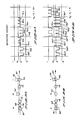
- an information track 60 is shown schematically as it would appear on an optical media recording disk.
- the sides or boundaries of the normal track width are shown by dotted lines at 62, 64.
- the information track is shown with schematically indicated information bits written at 66, 70, 74, 68, 76.
- the plus one order radiation beam is shown impinging at a spot 78 on the information bit 66.
- the zero order radiation beam impinges at a spot 72 and the minus one order radiation beam impinges at a spot 80 on the information bit 76.
- Fig. 2A illustrates the case where the diffraction grating 22 of Fig.
- FIG. 1 is one extreme position of its oscillation showing the plus one and minus one order radiation beams disposed equally and oppositely with respect to the centre line of the information track 60.
- Fig. 2B shows the same relationship of information bits 66, 70, 74, 68, 76 with respect to an information track 60. However, in Fig. 2B the diffraction grating 22 is at the opposite extreme position of its oscillation from that shown in Fig. 2A, the plus one order radiation beam and minus one order radiation beam, respectively impinging at spots 82, 84.
- the information track 60 is again shown with an arrow indicating the direction of motion of the optical media recording disk with respect to the radiation beams.
- the position of an optical read/ write head (not shown) is displaced with respect to the centre line of the information track 60 so that the spot 78 formed by the plus one order radiation beam is displaced totally off the information track so that the reflected radiation beam as detected by the detector 50 would not show information bits 66, 70, 74, 68, 76.
- the spot 72 formed by the zero order radiation beam is off the centre line of the information track 60 and will only partially detect with a partial signal the information bits in the information track.
- spot 80 formed by the minus one order radiation beam is closer to the centre of the information track 60 and fully detects information bits on the information track. This is as opposed to the condition of only partially detecting information bits which would normally occur if the spot 72 is centered on the information track 60.
- the detected signal of detector 50 is shown diagrammatically with respect to time as a straight line showing that the detector does not detect any of the information bits.
- the main detector 54 is shown schematically producing only a partial detected signal for information bits at peaks 66a, 70a, 74a, 68a, 76a.
- the detector 52 detects, in this position, a full detected signal for the information bits as shown at peaks 66b, 70b, 74b, 68b, 76b.
- the difference signal between the detectors 50, 52 clearly shows that the information track is off centre with respect to the zero order radiation beam and shows the direction in which the track is off centre so that an error signal can be generated showing the amount and direction of movement required to restore proper track centering.
- This error signal becomes available with a strong difference signal while the main detector 54 is still producing a useable detected signal. Note, however, that the detected signal of the main detector, while diminished and indicating the information track is off centre, alone does not indicate in which direction movement is required to restore proper track centering. Thus, an information track centering system based on only a single detector will show that an information track is off centre but will not produce information to show the direction of movement required to restore proper track centering.
- FIG. 3B represents a condition in which the zero order radiation beam reflected back to the main detector 54 represents an on-track and centered condition as shown by the spot 72.
- the spot 78 formed by the plus one order beam is shown partially reading the information bit 66 while the spot 80 formed by the minus one order beam is shown partially reading the information bit 76.
- Figure 4B shows the detected signals from the detectors 50, 52, 54 corresponding to the situation shown in Fig. 3B.
- the detector 50 produces only a partial detected signal for information bits at peaks 66c, 70c, 74c, 68c, 76c and the detector 52 produces only a partial detected signal for information bits at peaks 66d, 70d, 74d, 68d, 76d. It is noted, that because of the displacement with respect to the spots 32, 40 reflected back to detectors 50, 52 respectively, the detected signals represented in Fig. 4B are correspondingly time displaced on the time axis. The detected signal from the main detector 54 shows larger signal peaks representing a full strength reading condition where the zero order radiation beam encounters the information bits at peaks 66f, 70f, 74f, 68f, 76f.
- the bit density per track and the rate of revolution of the optical media recording disk is such that numerous information bits should pass beneath the detectors 50, 52, 54 as the diffraction grating 22 oscillates.
- an optical recording system using the present invention could operate at a data rate of approximately 2.5 MHz while the diffraction grating may oscillate at 20 KHz.
- a total of 125 information bits may pass beneath the detectors during each complete oscillation of the diffraction grating 22.
- the detectors 50, 52 are designed in combination with the differential amplifier 56 so that a time average signal is formed of the detected signals shown, for example, in Figs. 4A and 4B.
- the output signal from the differential amplifier 56 will be a time averaged signal to eliminate individual peaks representative of individual information bits on the information track.
- the band pass filter 58 removes any unwanted signal outside the frequency spectrum for error detection and correction.
- the synchronous amplifier-detector 48 in conjunction with the band pass filter 58 acts to amplify the error signal and to switch the sense of the error signal in synchronization with the switching of the plus one order and minus one order radiation beams from one side to the other side of the centre of the information track. That is, the error signal must contain both amplitude information representative of the degree to which the information track is off centre and the direction required to restore proper track centering. However, because the plus one and minus one order radiation beams move constantly from one side of the track to the other, the detectors also must be switched constantly in order to preserve the proper sense of the detected signals.
Landscapes
- Optical Recording Or Reproduction (AREA)
Claims (7)
Applications Claiming Priority (2)
| Application Number | Priority Date | Filing Date | Title |
|---|---|---|---|
| US06/359,641 US4462095A (en) | 1982-03-19 | 1982-03-19 | Moving diffraction grating for an information track centering system for optical recording |
| US359641 | 1982-03-19 |
Publications (3)
| Publication Number | Publication Date |
|---|---|
| EP0089736A2 EP0089736A2 (de) | 1983-09-28 |
| EP0089736A3 EP0089736A3 (en) | 1983-11-16 |
| EP0089736B1 true EP0089736B1 (de) | 1986-07-16 |
Family
ID=23414707
Family Applications (1)
| Application Number | Title | Priority Date | Filing Date |
|---|---|---|---|
| EP83300506A Expired EP0089736B1 (de) | 1982-03-19 | 1983-02-01 | Informationsspur-Zentriersystem |
Country Status (6)
| Country | Link |
|---|---|
| US (1) | US4462095A (de) |
| EP (1) | EP0089736B1 (de) |
| JP (1) | JPS58208947A (de) |
| AU (1) | AU550580B2 (de) |
| CA (1) | CA1191256A (de) |
| DE (1) | DE3364457D1 (de) |
Families Citing this family (40)
| Publication number | Priority date | Publication date | Assignee | Title |
|---|---|---|---|---|
| JPS5958637A (ja) * | 1982-09-28 | 1984-04-04 | Sony Corp | 光学式再生装置 |
| JPS59119548A (ja) * | 1982-12-25 | 1984-07-10 | Pioneer Electronic Corp | 光学式ピツクアツプ装置 |
| JPS59139152A (ja) * | 1983-01-28 | 1984-08-09 | Canon Inc | 光情報再生方法および装置 |
| US4695992A (en) * | 1983-01-31 | 1987-09-22 | Canon Kabushiki Kaisha | Optical information recording-reproducing apparatus in which the relative position of a primary beam and secondary beams on recording medium is varied during recording and reproduction of information |
| US4530079A (en) * | 1983-03-23 | 1985-07-16 | Xerox Corporation | Track following system for optical disc drive |
| DE3323007C1 (de) * | 1983-06-25 | 1984-06-28 | Deutsche Thomson-Brandt Gmbh, 7730 Villingen-Schwenningen | Spurfolgesystem mit einem optischen Abtaster für ein Audio- oder Video-Plattenwiedergabegerät |
| JPS6069840A (ja) * | 1983-09-22 | 1985-04-20 | Canon Inc | 情報記録又は再生装置 |
| DE3339736C1 (de) * | 1983-11-03 | 1985-06-05 | Deutsche Thomson-Brandt Gmbh, 7730 Villingen-Schwenningen | Spurfolgesystem zur Korrektur von Tangentenfehlwinkeln bei optischer Plattenabtastung |
| US4703408A (en) * | 1983-11-28 | 1987-10-27 | Hitachi, Ltd. | Apparatus and record carrier for optically writing information |
| US4670869A (en) * | 1984-01-03 | 1987-06-02 | Magnetic Peripherals Inc. | Switching laser beam apparatus with recombined beam for recording |
| US4598393A (en) * | 1984-04-06 | 1986-07-01 | Drexler Technology Corporation | Three-beam optical servo tracking system with two-track parallel readout |
| US4689481A (en) * | 1984-06-14 | 1987-08-25 | Nec Corporation | Focus error detector and optical head using the same |
| JPS6124033A (ja) * | 1984-07-13 | 1986-02-01 | Sony Corp | 光学式ヘツドのトラツキング誤差検出装置 |
| DE3533647C2 (de) * | 1984-09-20 | 1994-09-01 | Pioneer Electronic Corp | Optisches Informationsaufzeichnungs- und Wiedergabegerät |
| JPH0792916B2 (ja) * | 1985-02-08 | 1995-10-09 | 松下電器産業株式会社 | 光学記録信号再生方法 |
| NL8502835A (nl) * | 1985-10-17 | 1987-05-18 | Philips Nv | Inrichting voor het met optische straling aftasten van een informatievlak. |
| US4727528A (en) * | 1986-04-22 | 1988-02-23 | Sri International | Optical media tracking method and apparatus for optical storage system |
| EP0245821A3 (en) * | 1986-05-12 | 1988-07-20 | Csk Corporation | Data record formatting system and reading/writing system for optical recording medium |
| JPH06101125B2 (ja) * | 1986-05-21 | 1994-12-12 | キヤノン株式会社 | 光学的情報記録再生装置 |
| KR900008380B1 (ko) * | 1986-07-01 | 1990-11-17 | 미쓰비시덴기 가부시기 가이샤 | 광학식 헤드장치 |
| US4918675A (en) * | 1986-12-04 | 1990-04-17 | Pencom International Corporation | Magneto-optical head with separate optical paths for error and data detection |
| US4905216A (en) * | 1986-12-04 | 1990-02-27 | Pencom International Corporation | Method for constructing an optical head by varying a hologram pattern |
| DE3804701A1 (de) * | 1987-03-20 | 1988-09-29 | Hitachi Ltd | Mehrfachlichtfleck-lageregeleinrichtung |
| US4843603A (en) * | 1988-03-11 | 1989-06-27 | Optotech, Inc. | Concentric photodetector arrangement for focusing and tracking |
| US5073888A (en) * | 1988-04-21 | 1991-12-17 | Ricoh Company, Ltd. | Optical pickup device |
| US5511050A (en) * | 1988-09-21 | 1996-04-23 | Hitachi, Ltd. | Focus error detecting method and optical head using the same |
| JPH0770066B2 (ja) * | 1988-10-27 | 1995-07-31 | パイオニア株式会社 | 光軸モニタ装置 |
| JPH0748263B2 (ja) * | 1989-06-27 | 1995-05-24 | 三菱電機株式会社 | 光記録再生装置 |
| JPH03100931A (ja) * | 1989-09-14 | 1991-04-25 | Mitsubishi Electric Corp | 光学式情報記録再生装置 |
| US5173598A (en) * | 1991-05-10 | 1992-12-22 | U.S. Philips Corporation | Optical scanning beam position control system which is free of modulation by tracking error |
| BE1007872A3 (nl) * | 1993-12-15 | 1995-11-07 | Philips Electronics Nv | Optische aftastinrichting, alsmede een opteken- en/of uitleesinrichting voorzien van een dergelijke aftastinrichting. |
| US5917797A (en) * | 1997-08-15 | 1999-06-29 | Zen Research Nv | Multi-beam optical pickup assembly and methods using a compact two-dimensional arrangement of beams |
| US6411573B1 (en) | 1998-02-20 | 2002-06-25 | Zen Research (Ireland), Ltd. | Multi-beam optical pickup |
| WO1999063536A2 (en) * | 1998-06-05 | 1999-12-09 | Massachusetts Institute Of Technology | Very-high-density memory device utilizing a scintillating data-storage medium |
| DE60044686D1 (de) * | 1999-04-21 | 2010-08-26 | Fujifilm Corp | Verfahren zur Korrektur der Lage eines Lichtbündels in einem Abtastgerät |
| DE19936007A1 (de) | 1999-08-04 | 2001-02-15 | Thomson Brandt Gmbh | Gerät zum Lesen und/oder Beschreiben optischer Aufzeichnungsträger |
| WO2003096053A2 (en) * | 2002-05-09 | 2003-11-20 | Amit Stekel | Automatic certification, identification and tracking of remote objects in relative motion |
| JP2011044209A (ja) * | 2009-08-24 | 2011-03-03 | Hitachi-Lg Data Storage Inc | 光ディスク装置および光ディスク再生方法 |
| DE102009029234A1 (de) * | 2009-09-07 | 2011-03-10 | Robert Bosch Gmbh | Laserprojektor zur Fahrwerksvermessung |
| CN110968122B (zh) * | 2019-11-28 | 2023-05-02 | 歌尔股份有限公司 | 一种线性传送系统的位置获取方法及线性传送系统 |
Family Cites Families (4)
| Publication number | Priority date | Publication date | Assignee | Title |
|---|---|---|---|---|
| AR205839A1 (es) * | 1974-09-30 | 1976-06-07 | Mca Disco Vision | Servodisposicion para recorrer opticamente y leer simultaneamente un canal de informacion almacenado en un disco de video |
| NL174609C (nl) * | 1975-10-15 | 1984-07-02 | Philips Nv | Volgspiegelinrichting in een optische platenspeler. |
| JPS5398802A (en) * | 1977-02-09 | 1978-08-29 | Mitsubishi Electric Corp | Optical reproducer |
| NL7802860A (nl) * | 1978-03-16 | 1979-09-18 | Philips Nv | Registratiedragerlichaam en registratiedrager voor optische informatie en inrichting voor het inschrijven en uitlezen. |
-
1982
- 1982-03-19 US US06/359,641 patent/US4462095A/en not_active Expired - Fee Related
-
1983
- 1983-01-13 CA CA000419435A patent/CA1191256A/en not_active Expired
- 1983-02-01 EP EP83300506A patent/EP0089736B1/de not_active Expired
- 1983-02-01 DE DE8383300506T patent/DE3364457D1/de not_active Expired
- 1983-02-08 JP JP58018270A patent/JPS58208947A/ja active Granted
- 1983-02-09 AU AU11271/83A patent/AU550580B2/en not_active Ceased
Also Published As
| Publication number | Publication date |
|---|---|
| EP0089736A3 (en) | 1983-11-16 |
| JPS58208947A (ja) | 1983-12-05 |
| AU1127183A (en) | 1983-09-22 |
| EP0089736A2 (de) | 1983-09-28 |
| US4462095A (en) | 1984-07-24 |
| AU550580B2 (en) | 1986-03-27 |
| JPH0344385B2 (de) | 1991-07-05 |
| DE3364457D1 (en) | 1986-08-21 |
| CA1191256A (en) | 1985-07-30 |
Similar Documents
| Publication | Publication Date | Title |
|---|---|---|
| EP0089736B1 (de) | Informationsspur-Zentriersystem | |
| EP0012603B1 (de) | Verfahren und Vorrichtung zum Folgen einer optisch lesbaren Datenspur | |
| CA1143062A (en) | Apparatus for correcting for temperature- induced tracking errors in a system for recovering information from a recording disc | |
| EP0011990B1 (de) | Verfahren und Vorrichtung zum Zentrieren eines Lichtstrahls auf einer Informationsspur | |
| EP0418087B1 (de) | Optischer Kopf | |
| EP0116467B1 (de) | Optische Plattenspieler | |
| JPS606014B2 (ja) | 情報検出装置 | |
| EP0391691B1 (de) | Gerät zur optischen Aufzeichnung und Wiedergabe | |
| EP0145787B1 (de) | Anordnung zur spurnachlaufregelung auf einer aufgezeichneten platte eines wiedergabegerätes | |
| JP2002117538A (ja) | マルチトラック光データ記録及び読出し | |
| JPS63858B2 (de) | ||
| JPH0373935B2 (de) | ||
| US5559771A (en) | Tracking control apparatus and optical pickup having the same | |
| US7136241B2 (en) | Information writing device | |
| JP2667968B2 (ja) | 光ディスク装置 | |
| JP2590889B2 (ja) | トラッキング制御装置 | |
| JP2591344B2 (ja) | 光学的トラック追跡装置 | |
| JPS63100627A (ja) | 光デイスク装置 | |
| EP0440810A1 (de) | Optisches speichersystem | |
| JPS63100628A (ja) | 光学的記録再生装置 | |
| JPS63229627A (ja) | 光学的記録再生装置 | |
| JPS649656B2 (de) | ||
| JPS59207439A (ja) | 光デイスクシステムにおけるビ−ムアクセス装置 | |
| JPH05197988A (ja) | 光ディスク装置 | |
| JPH05159341A (ja) | 光ピックアップ装置 |
Legal Events
| Date | Code | Title | Description |
|---|---|---|---|
| PUAI | Public reference made under article 153(3) epc to a published international application that has entered the european phase |
Free format text: ORIGINAL CODE: 0009012 |
|
| PUAL | Search report despatched |
Free format text: ORIGINAL CODE: 0009013 |
|
| AK | Designated contracting states |
Designated state(s): DE FR GB NL |
|
| AK | Designated contracting states |
Designated state(s): DE FR GB NL |
|
| 17P | Request for examination filed |
Effective date: 19840323 |
|
| GRAA | (expected) grant |
Free format text: ORIGINAL CODE: 0009210 |
|
| AK | Designated contracting states |
Kind code of ref document: B1 Designated state(s): DE FR GB NL |
|
| ET | Fr: translation filed | ||
| REF | Corresponds to: |
Ref document number: 3364457 Country of ref document: DE Date of ref document: 19860821 |
|
| PLBE | No opposition filed within time limit |
Free format text: ORIGINAL CODE: 0009261 |
|
| STAA | Information on the status of an ep patent application or granted ep patent |
Free format text: STATUS: NO OPPOSITION FILED WITHIN TIME LIMIT |
|
| 26N | No opposition filed | ||
| PGFP | Annual fee paid to national office [announced via postgrant information from national office to epo] |
Ref country code: GB Payment date: 19891231 Year of fee payment: 8 |
|
| PGFP | Annual fee paid to national office [announced via postgrant information from national office to epo] |
Ref country code: FR Payment date: 19900111 Year of fee payment: 8 |
|
| PGFP | Annual fee paid to national office [announced via postgrant information from national office to epo] |
Ref country code: DE Payment date: 19900117 Year of fee payment: 8 |
|
| PGFP | Annual fee paid to national office [announced via postgrant information from national office to epo] |
Ref country code: NL Payment date: 19900228 Year of fee payment: 8 |
|
| REG | Reference to a national code |
Ref country code: GB Ref legal event code: 732 |
|
| NLS | Nl: assignments of ep-patents |
Owner name: CONTROL DATA CORPORATION TE MINNEAPOLIS, MINNESOTA |
|
| REG | Reference to a national code |
Ref country code: FR Ref legal event code: TP |
|
| PG25 | Lapsed in a contracting state [announced via postgrant information from national office to epo] |
Ref country code: GB Effective date: 19910201 |
|
| PG25 | Lapsed in a contracting state [announced via postgrant information from national office to epo] |
Ref country code: NL Effective date: 19910901 |
|
| GBPC | Gb: european patent ceased through non-payment of renewal fee | ||
| NLV4 | Nl: lapsed or anulled due to non-payment of the annual fee | ||
| PG25 | Lapsed in a contracting state [announced via postgrant information from national office to epo] |
Ref country code: FR Effective date: 19911031 |
|
| PG25 | Lapsed in a contracting state [announced via postgrant information from national office to epo] |
Ref country code: DE Effective date: 19911101 |
|
| REG | Reference to a national code |
Ref country code: FR Ref legal event code: ST |