EP0089931A2 - Appareil pour l'analyse et le traitement numérique d'images en demi-tons - Google Patents
Appareil pour l'analyse et le traitement numérique d'images en demi-tons Download PDFInfo
- Publication number
- EP0089931A2 EP0089931A2 EP83830059A EP83830059A EP0089931A2 EP 0089931 A2 EP0089931 A2 EP 0089931A2 EP 83830059 A EP83830059 A EP 83830059A EP 83830059 A EP83830059 A EP 83830059A EP 0089931 A2 EP0089931 A2 EP 0089931A2
- Authority
- EP
- European Patent Office
- Prior art keywords
- white
- output
- circuit
- threshold
- tone
- Prior art date
- Legal status (The legal status is an assumption and is not a legal conclusion. Google has not performed a legal analysis and makes no representation as to the accuracy of the status listed.)
- Granted
Links
Images


Classifications
-
- H—ELECTRICITY
- H04—ELECTRIC COMMUNICATION TECHNIQUE
- H04N—PICTORIAL COMMUNICATION, e.g. TELEVISION
- H04N1/00—Scanning, transmission or reproduction of documents or the like, e.g. facsimile transmission; Details thereof
- H04N1/40—Picture signal circuits
- H04N1/403—Discrimination between the two tones in the picture signal of a two-tone original
-
- H—ELECTRICITY
- H04—ELECTRIC COMMUNICATION TECHNIQUE
- H04N—PICTORIAL COMMUNICATION, e.g. TELEVISION
- H04N1/00—Scanning, transmission or reproduction of documents or the like, e.g. facsimile transmission; Details thereof
- H04N1/40—Picture signal circuits
- H04N1/40062—Discrimination between different image types, e.g. two-tone, continuous tone
-
- H—ELECTRICITY
- H04—ELECTRIC COMMUNICATION TECHNIQUE
- H04N—PICTORIAL COMMUNICATION, e.g. TELEVISION
- H04N1/00—Scanning, transmission or reproduction of documents or the like, e.g. facsimile transmission; Details thereof
- H04N1/40—Picture signal circuits
- H04N1/405—Halftoning, i.e. converting the picture signal of a continuous-tone original into a corresponding signal showing only two levels
- H04N1/4051—Halftoning, i.e. converting the picture signal of a continuous-tone original into a corresponding signal showing only two levels producing a dispersed dots halftone pattern, the dots having substantially the same size
Definitions
- the present invention relates to an apparatus for scanning and digitally processing images with half tones, that is images (photographs or illustrations with greys or colours) which have tones intermediate between black and white.
- the invention relates to an apparatus of the type comprising:
- the object of the invention is to provide an apparatus for scanning and digitally processing images with half tones which allows the reconstruction of an image more faithfully than is possible with conventional apparatus in a manner which is simpler, more versatile and more economic.
- the present invention provides an apparatus of the type specified above, the main characteristic of which lies in the fact that it further includes
- the apparatus may further include a sampling and control circuit connected between the threshold comparator circuits and the digital-signal generator circuit and arranged to sample the outputs of the threshold comparator circuits at a predetermined frequency and, at each sampling, to cause the output by the generator circuit of the combination of digital signals corresponding to the half tone currently indicated by the signals provided at the output of the threshold comparator circuits.
- the scanning device may include, for example, a linear array of photo-detectors for examining the image elements of successive lines of an image and for outputting an analogue signal substantially representing the succession of the signals output by the individual photo-detectors.
- the sampling and control circuit includes regulating means for modifying the frequency of sampling of the outputs of the threshold comparator circuits.
- the outputs of the threshold comparator circuits may be sampled at a frequency which can be modified and in particular at a different frequency which is greater than that of interrogation of the photo-detectors of the scanning device, it is possible to achieve the reconstruction (printing) of the .image scanned with a different definition and particularly a greater definition than that of scanning of the examined image.
- the invention also relates to an apparatus for scanning and digitally processing composite images, that is, comprising half-tone image portions and white/ black image portions.
- Figure 1 illustrates a system for the reproduction of an image with half tones.
- a scanning device 1 including a linear array of photo-detectors, by means of mirrors M and an objective LL.
- the scanning of the entire original page 0 is carried out by the movement of the lamps L and the mirrors M at a predetermined velocity in the direction of the arrow F.
- the signals output by the scanning device 1 reach a processing circuit 3 described in greater detail below with reference to Figure 2, which outputs image signals, for example, to a compression module 4. Compression having occurred, the image signals are transmitted to a decoder module 5, for example, via a memory system 6 or via a transmission line or channel by means of two modems 7, 8.
- the decoder module 5 then outputs control signals to image-reproducing apparatus which may be constituted, for example, by a video terminal 9 or by a thermal printer 10, or even by a laser printer 11.
- each line of the original 0 is carried out,as indicated previously, by means of the array 1, for example, of charge-coupled cells (CCDS) 2, each of which examines an image element (pixel) with a predetermined definition.
- the cells of the array 1 are interrogated at a predetermined frequency established by a timing pulse generator circuit (clock) 20.
- the outputs of the individual cells 2 are serialised and fed to the input of a filter 21 which outputs an analogue signal.
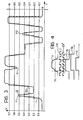
- the curve shown in continuous outline illustrates, by way of example, variation of the analogue signal V output by the filter 21 as a function of the time T during the course of scanning an entire elementary line of the original 0.
- the signal V is fed to the inputs of a plurality of threshold comparator circuits C.
- a plurality of threshold comparator circuits C In the example of Figure 2, seven threshold comparators are shown indicated respectively by C to C . These comparator circuits compare the signal V with respective threshold voltages indicated by S to S 7 in Figures 2 and 3. These threshold voltages are formed in a manner known per se by means of a series of resistors R 1 to R 8 located between a d.c. voltage source and earth.
- the threshold voltages S to S 7 divide the field of the maximum range of the signal V into eight bands indicated B, G1 to G 6 and W in Figure 3.
- One half tone is associated with each of the bands and in particular the band B corresponds to black, the bands G 1 to G 6 correspond to six grey tones and the band W corresponds to white.
- the threshold voltages S 1 to S 7 thus define a half-tone scale.
- the outputs of the threshold comparator circuits C 1 to C 7 are connected to the set inputs of flip-flops FF to FF .
- the reset input of these flip-flops are connected to a clock 22.
- the effect of the threshold comparator circuits C to C 7 and the flip-flops FF to FF is to cause the signal V to undergo a form of analogue to digital conversion with successive samplings being carried out at the frequency established by the clock 22.
- the outputs of the flip-flops are connected to six AND gates indicates A 1 to A 6 in Figure 2.
- the i'th gate A i has a first input connected to the output of the flip-flop FF i and a second input connected to the complementary or inverse output of the flip-flop FF i+1 .
- the outputs of the gates A 1 to A 6 are connected to the selection inputs of a digital-signal generator circuit 23 arranged to generate a plurality of combinations of digital signals (for example, sequences) each of which is indicative of a respective predetermined matrix pattern of white or black points associated with a respective half tone of the scale previously defined.
- Figure 5 illustrates several patterns by way of example, which are usable for the reproduction of black, of six half tones and of white.
- the patterns illustrated in Figure 5 essentially comprise lines of alternating black and white points, with intervening white or black lines.
- a matrix may thus be associated with black, with each grey tone and with white.
- Each matrix may be identified by means of sequences of digital signals (bits). In each of these sequences a "0" may correspond, for example, to a white point while a "1" corresponds to a black point.
- the digital-signal generator circuit 23 is arranged to generate the bit sequences which define the lines and hence the pattern of the half tone identified at a particular time by the state of the outputs of the gates A to A 6 considered in their entirety.
- the generator circuit 23 may be easily formed by a sequential logic network comprising a plurality of AND and NAND gates.
- the output of the pulse sequences by the digital-signal generator circuit 23 is clocked by a line counter circuit indicated 24.
- the output of the generator circuit 23 is connected to a first input of an OR gate 25 a second input of which is connected to the output of the flip-flop FF .
- the OR gate 25 emits a sequence of signals which serve to identify the pattern of the grey band in which the sampled value of the signal V falls.
- the clock 22 is of the type whose frequency can be varied, by means of an external control, between a certain number of predetermined frequencies.
- the timing pulse generator circuit 22 may include a series of oscillator circuits each of which generate pulses at a different respective frequency.
- the possibility of varying the frequency of sampling of the signal V gives considerable advantages which will become evident from the considerations which will now be turned to with reference to Figure 4.
- the waveform indicated v exemplifies a portion of the signal V on an expanded time scale.
- S i indicates generically one of the thresholds S to S 7 .
- the waveform indicated CK represents the signal output by the clock 20 which controls the scanning of the cells 2 of the array 1.
- the waveform indicated a indicates the signal output by the threshold comparator C which compares the signal v with the threshold level S i .
- a 50% increase in the sampling frequency gives a waveform c which is more faithful to the original signal V but described with six bits instead of four, that is again with an increase of 50%.
- a 50% increase in the sampling frequency enables the provision of the necessary digital signals for controlling a printer with a 50% increase in definition, that is with a definition of 12 pixels/mm.
- the relative minimum N also falls in the grey bands although this relates to a black point.
- the peaks P 1 , P 2 and the relative minimum N are treated as grey zones and hence, in the case of thin characters, one would as a result, obtain printed characters with a typical increase in the greys and falling off in the legibility of the image reproduced. This may happen even at the edges of thicker characters with a rather disagreeable effect.
- a variable threshold comparator circuit 26 is provided in the processing circuit 3 illustrated in Figure 2, for generating image signals usable for the reproduction of the image portions in white/black.
- the inputs of the circuit are connected in order to the outputs of the flip-flops FF to FF - .
- the connections between the flip-flops and the inputs of the circuits 26 are not illustrated.
- the circuit 26 is essentially a variable threshold comparison circuit which, by means of an algorithm which could be characterised as "in pursuit" achieves the automatic adaptation of the comparison threshold to the value progressively assumed by the signal V.
- the circuit 26 assumes the thxeshold S 1 to be the transition threshold. This means that when the signal V is less than S 1 it is interpreted as relating to black image portions, while when it is greater than this threshold it is interpreted as relat ing to white image portions.
- the first blacl/white transition occurs at the point I.
- the signal V then passes through the successive thresholds S 2 to S 5 without the circuit 26 effecting further transitions
- This circuit as the signal V traverses new thresholds disables the preceding threshold S 1 and assumes the last threshold traversed by the signal V for the next transition.
- the last threshold encountered by the signal V when increasing is taken as the threshold for the reverse transition (white/black) whenever the signal V is decreasing.
- the first white/black. transition thus occurs at the point II and then a subsequent black/white transition occurs at the point III.
- the circuit 25 thus provides a variable transition-threshold having, in the example of Figure 3, a varying form as given in broken line in the drawing.
- variable threshold comparator circuit 26 can be easily designed by utilizing bistable circuits (flip-flops), multiflexers and common logic gates.
- a logic control circuit 27 For processing composite images, a logic control circuit 27 having two inputs connected respectively to the outputs of the flip flops FF 1 and FF 7 , counts, in the manner which will be described next, the number of consecutive image elements corresponding to half tones in the grey bands G l to G6.
- This logic circuit 27 controls a switch device 28 with two positions or states, for selectively connecting an output conductor 29a to the output of the OR gate 25 or the output of the circuit 26.
- the logic circuit 27 can include, for example, a flip flop circuit a delay circuit (for example one or more counter circuits) and a counter (pixel counter).
- the said flip flop circuit When signal V exceeds reference signal S 1 or falls below reference signal S 7 , the said flip flop circuit is set and delivers a start signal to the pixel counter and a control signal to the delay circuit, at the same time.
- the pixel counter counts the pixels at the frequency of the timing pulse generator (clock) 22. If, within a predetermined lapse of time (delay time of the delay circuit), the pixel counter has reached number Q the delay circuit is reset, otherwise after the said lapse of time the delay circuit causes the switching of the switch device 28.
- two delay lines DL 1 and DL 2 are connected between the switch device 28 and the outputs of the OR gate 25 and the circuit 26.
- the delay lines DL 1 , DL delay the signals provided at the outputs of the OR gate 25 and the circuit 26 by a delay time corresponding to the time required for the logic circuit 27 to reach the end of its count.
- the scanning and image processing apparatus described above thus allows the precise and faithful reproduction of documents with mixed alphanumeric graphical/half tone content.
Landscapes
- Engineering & Computer Science (AREA)
- Multimedia (AREA)
- Signal Processing (AREA)
- Facsimile Image Signal Circuits (AREA)
- Image Input (AREA)
Applications Claiming Priority (2)
| Application Number | Priority Date | Filing Date | Title |
|---|---|---|---|
| IT67360/82A IT1201920B (it) | 1982-03-22 | 1982-03-22 | Apparecchiatura per la scansione ed il trattamento numerico di immagini con mezzi toni |
| IT6736082 | 1982-03-22 |
Publications (3)
| Publication Number | Publication Date |
|---|---|
| EP0089931A2 true EP0089931A2 (fr) | 1983-09-28 |
| EP0089931A3 EP0089931A3 (en) | 1985-09-04 |
| EP0089931B1 EP0089931B1 (fr) | 1988-11-09 |
Family
ID=11301746
Family Applications (1)
| Application Number | Title | Priority Date | Filing Date |
|---|---|---|---|
| EP83830059A Expired EP0089931B1 (fr) | 1982-03-22 | 1983-03-17 | Appareil pour l'analyse et le traitement numérique d'images en demi-tons |
Country Status (5)
| Country | Link |
|---|---|
| US (1) | US4554594A (fr) |
| EP (1) | EP0089931B1 (fr) |
| JP (1) | JPS58207771A (fr) |
| DE (1) | DE3378453D1 (fr) |
| IT (1) | IT1201920B (fr) |
Cited By (5)
| Publication number | Priority date | Publication date | Assignee | Title |
|---|---|---|---|---|
| GB2152324A (en) * | 1983-12-09 | 1985-07-31 | Canon Kk | Image processing device |
| GB2166921A (en) * | 1984-10-11 | 1986-05-14 | Canon Kk | Dual-mode image processing |
| EP0236594A1 (fr) * | 1985-12-24 | 1987-09-16 | Océ-Nederland B.V. | Procédé et appareil de reconnaissance d'information d'images en demi-ton |
| FR2652971A1 (fr) * | 1989-10-09 | 1991-04-12 | Sagem | Dispositif de transformation d'un signal d'analyse d'image en un signal binaire. |
| EP0279419A3 (fr) * | 1987-02-17 | 1992-03-04 | Sharp Kabushiki Kaisha | Codeur binaire de signaux d'images |
Families Citing this family (18)
| Publication number | Priority date | Publication date | Assignee | Title |
|---|---|---|---|---|
| US4545070A (en) * | 1982-04-30 | 1985-10-01 | Fuji Electric Company, Ltd. | Pattern discriminator |
| JPS59225675A (ja) * | 1983-06-07 | 1984-12-18 | Canon Inc | フアクシミリ電送方法およびその装置 |
| JPH0669212B2 (ja) * | 1984-02-20 | 1994-08-31 | 日本電気株式会社 | 適応擬似中間調化回路 |
| JPS60247381A (ja) * | 1984-05-22 | 1985-12-07 | Hitachi Medical Corp | 画像読取装置 |
| US4723173A (en) * | 1984-05-31 | 1988-02-02 | Canon Kabushiki Kaisha | Image processing apparatus |
| US5255331A (en) * | 1984-06-20 | 1993-10-19 | The Governor And Company Of The Bank Of England | Production of an image model and inspection of a pixel representation of an image |
| JPS61136377A (ja) * | 1984-12-06 | 1986-06-24 | Ricoh Co Ltd | スキヤナ−装置 |
| JPS61290865A (ja) * | 1985-06-19 | 1986-12-20 | Ricoh Co Ltd | 中間調デジタル画像処理装置 |
| JPS6277637A (ja) * | 1985-10-01 | 1987-04-09 | Seiko Instr & Electronics Ltd | カラ−ハ−ドコピ−装置 |
| JPH02126771A (ja) * | 1988-11-07 | 1990-05-15 | Aisin Seiki Co Ltd | 画像情報の2値化方法および装置 |
| NL8901230A (nl) * | 1989-05-17 | 1990-12-17 | Oce Nederland Bv | Belichtings- en afdrukinrichting. |
| US5187594A (en) * | 1990-02-09 | 1993-02-16 | Graphic Edge, Inc. | Method of creating and applying half tone screen patterns |
| IL115166A (en) * | 1991-04-30 | 1997-02-18 | Scitex Corp Ltd | Apparatus and method for descreening |
| US6091891A (en) * | 1997-05-09 | 2000-07-18 | Lexmark International, Inc. | Method and apparatus for calibrating delay lines to create gray levels in continuous tone printing |
| US6213018B1 (en) | 1999-05-14 | 2001-04-10 | Pcc Artwork Systems | Flexographic printing plate having improved solids rendition |
| US6731405B2 (en) | 1999-05-14 | 2004-05-04 | Artwork Systems | Printing plates containing ink cells in both solid and halftone areas |
| US7580154B2 (en) * | 1999-05-14 | 2009-08-25 | Esko Ip Nv | Printing plates containing ink cells in both solid and halftone areas |
| US8132508B2 (en) | 2005-04-14 | 2012-03-13 | Esko Software Bvba | Method of controlling ink film thickness on a printing plate |
Family Cites Families (14)
| Publication number | Priority date | Publication date | Assignee | Title |
|---|---|---|---|---|
| DE1762412A1 (de) * | 1968-06-12 | 1970-05-06 | Telefunken Patent | Einrichtung in einer Datenverarbeitungsanlage mit einer Analog-Digital-Umsetzungsstufe und einem dieser nachgeschalteten Digitalspeicher |
| DE2017432A1 (de) * | 1970-04-11 | 1971-10-28 | Bosch Elektronik Gmbh | Verfahren zur elektrischen Übertragung von Bildvorlagen mit schwarzen, weißen und grauen Helligkeitswerten |
| US3662341A (en) * | 1970-09-25 | 1972-05-09 | Ibm | Video-derived segmentation-gating apparatus for optical character recognition |
| US4084196A (en) * | 1977-01-31 | 1978-04-11 | Dacom, Inc. | Electronic half-tone generating means for facsimile reproduction system |
| JPS54124619A (en) * | 1978-03-22 | 1979-09-27 | Fuji Xerox Co Ltd | Optical image reading method |
| JPS54144140A (en) * | 1978-05-01 | 1979-11-10 | Ricoh Co Ltd | Processing system for intermediate tone |
| JPS5513555A (en) * | 1978-07-14 | 1980-01-30 | Ricoh Co Ltd | Half tone reproducing method dependent upon binary picture element |
| JPS5537092A (en) * | 1978-09-05 | 1980-03-14 | Ibm | Mode switch for setting threshold value |
| US4194221A (en) * | 1978-12-26 | 1980-03-18 | Xerox Corporation | Automatic multimode continuous halftone line copy reproduction |
| US4214277A (en) * | 1979-02-02 | 1980-07-22 | Xerox Corporation | Halftone implementation apparatus |
| JPS55110382A (en) * | 1979-02-19 | 1980-08-25 | Seikosha Co Ltd | Recorder |
| GB2044500B (en) * | 1979-03-16 | 1983-03-16 | Hajime Industries | Signal processing counting apparatus |
| JPS56100572A (en) * | 1980-01-17 | 1981-08-12 | Fuji Photo Film Co Ltd | Signal processing system of variable density picture |
| JPS56143765A (en) * | 1980-04-10 | 1981-11-09 | Canon Inc | Processor for video signal |
-
1982
- 1982-03-22 IT IT67360/82A patent/IT1201920B/it active
-
1983
- 1983-03-17 DE DE8383830059T patent/DE3378453D1/de not_active Expired
- 1983-03-17 EP EP83830059A patent/EP0089931B1/fr not_active Expired
- 1983-03-18 US US06/476,559 patent/US4554594A/en not_active Expired - Lifetime
- 1983-03-22 JP JP58047818A patent/JPS58207771A/ja active Granted
Cited By (9)
| Publication number | Priority date | Publication date | Assignee | Title |
|---|---|---|---|---|
| GB2152324A (en) * | 1983-12-09 | 1985-07-31 | Canon Kk | Image processing device |
| US4866533A (en) * | 1983-12-09 | 1989-09-12 | Canon Kabushiki Kaisha | Image processing device |
| GB2166921A (en) * | 1984-10-11 | 1986-05-14 | Canon Kk | Dual-mode image processing |
| US4903143A (en) * | 1984-10-11 | 1990-02-20 | Canon Kabushiki Kaisha | Image processing apparatus |
| EP0236594A1 (fr) * | 1985-12-24 | 1987-09-16 | Océ-Nederland B.V. | Procédé et appareil de reconnaissance d'information d'images en demi-ton |
| US4740843A (en) * | 1985-12-24 | 1988-04-26 | Oce-Nederland B.V. | Method and device for recognizing half-tone image information |
| EP0279419A3 (fr) * | 1987-02-17 | 1992-03-04 | Sharp Kabushiki Kaisha | Codeur binaire de signaux d'images |
| FR2652971A1 (fr) * | 1989-10-09 | 1991-04-12 | Sagem | Dispositif de transformation d'un signal d'analyse d'image en un signal binaire. |
| EP0423018A1 (fr) * | 1989-10-09 | 1991-04-17 | Societe D'applications Generales D'electricite Et De Mecanique S A G E M | Dispositif de transformation d'un signal d'analyse d'image en un signal binaire |
Also Published As
| Publication number | Publication date |
|---|---|
| EP0089931A3 (en) | 1985-09-04 |
| JPH0430781B2 (fr) | 1992-05-22 |
| EP0089931B1 (fr) | 1988-11-09 |
| IT1201920B (it) | 1989-02-02 |
| IT8267360A0 (it) | 1982-03-22 |
| DE3378453D1 (en) | 1988-12-15 |
| US4554594A (en) | 1985-11-19 |
| JPS58207771A (ja) | 1983-12-03 |
Similar Documents
| Publication | Publication Date | Title |
|---|---|---|
| US4554594A (en) | Apparatus for scanning and digitally processing half-tone images | |
| US4485408A (en) | Halftone processing method for digital facsmile apparatus | |
| JPS6198069A (ja) | 画像処理装置 | |
| US4578711A (en) | Video data signal digitization and correction system | |
| DE3851393T2 (de) | Bildlesegerät. | |
| US4434431A (en) | Multilevel image printing device | |
| US4214277A (en) | Halftone implementation apparatus | |
| US4143401A (en) | System for generating line drawing of a scanned image | |
| DE3520028C2 (fr) | ||
| KR100376951B1 (ko) | 화소밀도변환및오차확산기능을갖는화상데이타처리장치 | |
| US4821115A (en) | Color hard copy apparatus having simplified analog-to-digital conversion with adjustable threshold levels | |
| US7697172B2 (en) | Image sensor, image reading device, and image resolution setting method | |
| GB2158319A (en) | A method of and apparatus for generating colour matte signals | |
| US4812910A (en) | Image reproducing equipment | |
| US5444832A (en) | Pixel density converter | |
| EP0336403A3 (fr) | Appareil de lecture d'images | |
| JPS5817778A (ja) | 2値化方式 | |
| JPS5821979B2 (ja) | 画像信号の網点処理方式 | |
| EP0479537A2 (fr) | Appareil de formation d'images | |
| US3585504A (en) | Electrical signalling system | |
| JP2730084B2 (ja) | イメージスキャナにおける撮像信号処理回路 | |
| JPS60152173A (ja) | 原稿画情報読取処理装置 | |
| JPS5875375A (ja) | 画像読取り装置 | |
| JPS61210768A (ja) | 画信号の2値化方法 | |
| CA1325267C (fr) | Appareil de traitement d'images |
Legal Events
| Date | Code | Title | Description |
|---|---|---|---|
| PUAI | Public reference made under article 153(3) epc to a published international application that has entered the european phase |
Free format text: ORIGINAL CODE: 0009012 |
|
| AK | Designated contracting states |
Designated state(s): DE FR GB |
|
| PUAL | Search report despatched |
Free format text: ORIGINAL CODE: 0009013 |
|
| AK | Designated contracting states |
Designated state(s): DE FR GB |
|
| 17P | Request for examination filed |
Effective date: 19860228 |
|
| 17Q | First examination report despatched |
Effective date: 19870820 |
|
| GRAA | (expected) grant |
Free format text: ORIGINAL CODE: 0009210 |
|
| AK | Designated contracting states |
Kind code of ref document: B1 Designated state(s): DE FR GB |
|
| REF | Corresponds to: |
Ref document number: 3378453 Country of ref document: DE Date of ref document: 19881215 |
|
| ET | Fr: translation filed | ||
| PLBE | No opposition filed within time limit |
Free format text: ORIGINAL CODE: 0009261 |
|
| STAA | Information on the status of an ep patent application or granted ep patent |
Free format text: STATUS: NO OPPOSITION FILED WITHIN TIME LIMIT |
|
| 26N | No opposition filed | ||
| PGFP | Annual fee paid to national office [announced via postgrant information from national office to epo] |
Ref country code: FR Payment date: 19930309 Year of fee payment: 11 |
|
| PGFP | Annual fee paid to national office [announced via postgrant information from national office to epo] |
Ref country code: DE Payment date: 19930324 Year of fee payment: 11 |
|
| PG25 | Lapsed in a contracting state [announced via postgrant information from national office to epo] |
Ref country code: FR Effective date: 19941130 |
|
| PG25 | Lapsed in a contracting state [announced via postgrant information from national office to epo] |
Ref country code: DE Effective date: 19941201 |
|
| REG | Reference to a national code |
Ref country code: FR Ref legal event code: ST |
|
| REG | Reference to a national code |
Ref country code: GB Ref legal event code: IF02 |
|
| PGFP | Annual fee paid to national office [announced via postgrant information from national office to epo] |
Ref country code: GB Payment date: 20020320 Year of fee payment: 20 |
|
| PG25 | Lapsed in a contracting state [announced via postgrant information from national office to epo] |
Ref country code: GB Free format text: LAPSE BECAUSE OF EXPIRATION OF PROTECTION Effective date: 20030316 |
|
| REG | Reference to a national code |
Ref country code: GB Ref legal event code: PE20 |