EP0089945B1 - Procédé de fabrication et d'empilage de grillages d'armature pour béton armé - Google Patents
Procédé de fabrication et d'empilage de grillages d'armature pour béton armé Download PDFInfo
- Publication number
- EP0089945B1 EP0089945B1 EP19830890032 EP83890032A EP0089945B1 EP 0089945 B1 EP0089945 B1 EP 0089945B1 EP 19830890032 EP19830890032 EP 19830890032 EP 83890032 A EP83890032 A EP 83890032A EP 0089945 B1 EP0089945 B1 EP 0089945B1
- Authority
- EP
- European Patent Office
- Prior art keywords
- wires
- transverse
- mats
- grid
- grid sheet
- Prior art date
- Legal status (The legal status is an assumption and is not a legal conclusion. Google has not performed a legal analysis and makes no representation as to the accuracy of the status listed.)
- Expired
Links
Images

Classifications
-
- B—PERFORMING OPERATIONS; TRANSPORTING
- B65—CONVEYING; PACKING; STORING; HANDLING THIN OR FILAMENTARY MATERIAL
- B65G—TRANSPORT OR STORAGE DEVICES, e.g. CONVEYORS FOR LOADING OR TIPPING, SHOP CONVEYOR SYSTEMS OR PNEUMATIC TUBE CONVEYORS
- B65G57/00—Stacking of articles
- B65G57/02—Stacking of articles by adding to the top of the stack
- B65G57/08—Stacking of articles by adding to the top of the stack articles being tilted or inverted prior to depositing
- B65G57/081—Stacking of articles by adding to the top of the stack articles being tilted or inverted prior to depositing alternate articles being inverted
-
- B—PERFORMING OPERATIONS; TRANSPORTING
- B21—MECHANICAL METAL-WORKING WITHOUT ESSENTIALLY REMOVING MATERIAL; PUNCHING METAL
- B21F—WORKING OR PROCESSING OF METAL WIRE
- B21F27/00—Making wire network, i.e. wire nets
- B21F27/08—Making wire network, i.e. wire nets with additional connecting elements or material at crossings
- B21F27/10—Making wire network, i.e. wire nets with additional connecting elements or material at crossings with soldered or welded crossings
-
- B—PERFORMING OPERATIONS; TRANSPORTING
- B21—MECHANICAL METAL-WORKING WITHOUT ESSENTIALLY REMOVING MATERIAL; PUNCHING METAL
- B21F—WORKING OR PROCESSING OF METAL WIRE
- B21F33/00—Tools or devices specially designed for handling or processing wire fabrics or the like
- B21F33/002—Coiling or packing wire network
-
- E—FIXED CONSTRUCTIONS
- E04—BUILDING
- E04C—STRUCTURAL ELEMENTS; BUILDING MATERIALS
- E04C5/00—Reinforcing elements, e.g. for concrete; Auxiliary elements therefor
- E04C5/01—Reinforcing elements of metal, e.g. with non-structural coatings
- E04C5/02—Reinforcing elements of metal, e.g. with non-structural coatings of low bending resistance, i.e. of essentially one-dimensional [1D] or two-dimensional [2D] extent
- E04C5/04—Mats
Definitions
- the turning and stacking of the mats usually provide special, automatic turning. and stacking devices, into which the mats emerging from the grid welding machine are inserted one after the other up to a stop, and which place the mats alternately unturned and turned on the stack.
- Mats with consistently straight longitudinal and transverse wires arrange themselves automatically when placed on the mat stack so that the parallel, identical wires of two mats placed directly one above the other come to lie in the same plane and do not, for example, remain on top of each other because wire the upper of the superimposed wires slide due to the action of gravity along the lateral surfaces of the lower.
- the projecting transverse wire end parts of which are bent back to the longitudinal edge wires in the form of loops to improve the transmission of force between mats laid next to one another in the form of loops, the shape of these loops poses a particular problem.
- the cross wires can no longer be arranged in the same plane, because the wire loops of mats placed one above the other prevent the cross wires from sliding against one another along their circumferential surfaces.
- the invention is therefore concerned with the task of avoiding the difficulties outlined above in a method of the type specified in the introduction for producing and stacking reinforcement meshes for reinforced concrete.
- a lattice web is first produced in which the protruding transverse wire end parts in the desired length of the reinforcement mats correspond to sections of the lattice web in the web plane, based on the lattice feed direction , are alternately bent forwards or backwards to the longitudinal longitudinal wires of the grid path, this grid path is then cut between two transverse wires with end parts bent back in opposite directions and the mats obtained in this way are alternately turned around and turned around their longitudinal axis and placed on a stack.
- the cross wires of adjacent mats in the stack can be arranged next to one another in one plane without mutual hindrance, despite the loop shape of their end parts, so that stacking that is as space-saving as possible is possible with mats with straight straight longitudinal and transverse wires.
- straight transverse wires are welded to a lattice web with the longitudinal wires in the grid welding machine, and the transverse wire end parts protruding beyond the longitudinal longitudinal wires are then bent back in a loop to the longitudinal longitudinal wires.
- the loop-shaped bending back of the transverse wire end parts takes place with the aid of bending devices attached to the grid welding machine in the feed path of the grid web.
- cross wires with end parts which have already been bent back in a loop are welded to the longitudinal wires to form a grid web in the grid welding machine.
- the loop-shaped bending back of the transverse wire end parts takes place in bending devices separated from the grid welding machine or in bending devices attached to this machine in the feeder path of the transverse wires.
- the cross wire end parts which are bent back in the form of a loop are advantageously welded to the longitudinal edge wires of the lattice web.
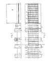
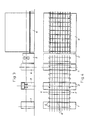
- FIG. 1 denotes a continuously operating grid welding machine, by means of which longitudinal wires L are withdrawn continuously or stepwise from reels and are joined together in a known manner with transverse wires Q to form a lattice track in such a way that the end parts E of the transverse wires Q laterally over the longitudinal edge wires survive the grid.
- a bending device 2 is provided, with the aid of which the protruding transverse wire end parts E in the grid production plane are bent back in the form of loops S to the longitudinal longitudinal wires of the grid web.
- the direction of direction in which this bending back of the transverse wire end parts E takes place is reversed in the sections of the grid web corresponding to the desired mat lengths.
- Figure 2 it can be seen that the end parts of the two transverse wires just in the bending device 2 were bent forwards in relation to the feed direction of the grid web, whereas the end parts of the cross wires of the previous section of the grid web which had already emerged from the bending device 2 were bent backwards have been.
- transverse wire end parts which are bent back to the longitudinal edge wires are advantageously welded to the longitudinal edge wires, for which purpose a welding device 3 is provided behind the bending device 2.
- the grid path is then cut between two adjacent transverse wires with end parts bent back in opposite directions by means of a mat shear 4 as soon as this point of the grid path designated X in FIG. 2 reaches the area of the shear 4 in the course of the grid advance.
- a transport device 5 which pushes the mats separated from the grid web into a turning and stacking device 6, which, in a known manner, alternately positions a mat in which it emerges from the mat scissors 4 onto the mat stack deposits and turns the next mat around its longitudinal axis before placing it on the stack of mats.
- FIG. 2 a top view of the mat stack in the area of the turning and stacking device can be seen grid mesh, the transverse wire end parts z. B. in the odd-numbered mats in the stack in the grid feed direction and in the even-numbered mats against the grid feed direction in the form of loops S to the longitudinal edge wires of the mats.
- FIG. 5 a cross-section in the direction of the longitudinal wires through a stack of four mats is shown in Figure 5 on a larger scale, the longitudinal and transverse wires are designated in turn with L1 to L4 or with Q1 to Q4, the of which The end faces of loops S1 to S4 formed in transverse wire end parts appear and the reference numerals of wires covered by visible wires are placed in brackets.
- the transverse wires Q1, Q2 and the loops S1, S2 formed by the transverse wire end parts of the first and second mat lie in a common plane, as can be seen in FIG.
- the longitudinal wires L2 and L3 of the second and third mat lie in a common plane.
- the cross wires can be fed individually to the mesh welding machine and the mesh web can be advanced for each feed step by a distance that is at least twice the outer width B of the fully formed loop S of a cross wire end part E, measured parallel to the mesh web plane.
- cross wires Q are fed to the grid welding machine with end parts which have already been bent back in the form of loops S.
- the orientation of these loops S with respect to the direction of advance of the lattice web is reversed in the sections corresponding to the desired mat length, and the lattice web is cut at the point X between two transverse wires with loops bent back in opposite directions by means of the scissors 4, again using those shown in FIGS. 5 and 6 explains the space-saving stacking possibility in the turning and stacking device 6.
Landscapes
- Engineering & Computer Science (AREA)
- Mechanical Engineering (AREA)
- Architecture (AREA)
- Civil Engineering (AREA)
- Structural Engineering (AREA)
- Wire Processing (AREA)
Claims (6)
Applications Claiming Priority (2)
| Application Number | Priority Date | Filing Date | Title |
|---|---|---|---|
| AT113382A AT373513B (de) | 1982-03-23 | 1982-03-23 | Verfahren zum herstellen und stapeln von bewehrungsmatten fuer stahlbeton |
| AT1133/82 | 1982-03-23 |
Publications (2)
| Publication Number | Publication Date |
|---|---|
| EP0089945A1 EP0089945A1 (fr) | 1983-09-28 |
| EP0089945B1 true EP0089945B1 (fr) | 1985-06-26 |
Family
ID=3507310
Family Applications (1)
| Application Number | Title | Priority Date | Filing Date |
|---|---|---|---|
| EP19830890032 Expired EP0089945B1 (fr) | 1982-03-23 | 1983-03-08 | Procédé de fabrication et d'empilage de grillages d'armature pour béton armé |
Country Status (5)
| Country | Link |
|---|---|
| EP (1) | EP0089945B1 (fr) |
| AT (1) | AT373513B (fr) |
| CH (1) | CH658093A5 (fr) |
| DE (1) | DE3360319D1 (fr) |
| GR (1) | GR77979B (fr) |
Families Citing this family (4)
| Publication number | Priority date | Publication date | Assignee | Title |
|---|---|---|---|---|
| FR2589128B1 (fr) * | 1985-10-28 | 1988-04-08 | Trefilunion | Dispositif de positionnement des treillis metalliques en vue de la constitution de piles regulieres |
| AT402033B (de) * | 1992-02-20 | 1997-01-27 | Evg Entwicklung Verwert Ges | Verfahren und anlage zum herstellen von bewehrungsgittermatten |
| CN107537959A (zh) * | 2017-09-13 | 2018-01-05 | 河北森阳建筑设备科技有限公司 | 生产保温板墙体用网架生产线 |
| CN109353835B (zh) * | 2018-12-21 | 2023-10-13 | 江苏江桥机械制造有限公司 | 一种自动高速砌块码垛生产线 |
Family Cites Families (4)
| Publication number | Priority date | Publication date | Assignee | Title |
|---|---|---|---|---|
| US2278104A (en) * | 1938-10-13 | 1942-03-31 | American Steel & Wire Co | Wire fabric device |
| AT289518B (de) * | 1968-05-28 | 1971-04-26 | Evg Entwicklung Verwert Ges | Verfahren zum Herstellen von metallischen Gitterbahnen und Gittermatten |
| DE2060219C3 (de) * | 1970-12-08 | 1975-07-31 | Wolfram 4993 Rahden Reinking | Verfahren und Vorrichtung zum maschinellen Stapeln von Beton-Stahlmatten |
| AT366937B (de) * | 1978-11-08 | 1982-05-25 | Evg Entwicklung Verwert Ges | Vorrichtung zum maschinellen stapeln von gittermatten unter abwechselndem wenden derselben |
-
1982
- 1982-03-23 AT AT113382A patent/AT373513B/de not_active IP Right Cessation
- 1982-12-08 CH CH716782A patent/CH658093A5/de not_active IP Right Cessation
-
1983
- 1983-03-08 EP EP19830890032 patent/EP0089945B1/fr not_active Expired
- 1983-03-08 DE DE8383890032T patent/DE3360319D1/de not_active Expired
- 1983-03-23 GR GR70874A patent/GR77979B/el unknown
Also Published As
| Publication number | Publication date |
|---|---|
| EP0089945A1 (fr) | 1983-09-28 |
| CH658093A5 (de) | 1986-10-15 |
| GR77979B (fr) | 1984-09-25 |
| ATA113382A (de) | 1982-12-15 |
| AT373513B (de) | 1984-01-25 |
| DE3360319D1 (en) | 1985-08-01 |
Similar Documents
| Publication | Publication Date | Title |
|---|---|---|
| EP0069108B1 (fr) | Procédé et dispositif pour fabriquer des corps de matelas soudés | |
| AT402033B (de) | Verfahren und anlage zum herstellen von bewehrungsgittermatten | |
| AT405621B (de) | Anlage zum kontinuierlichen herstellen von bauelementen | |
| DE2657667A1 (de) | Bauplatte mit einem aus metalldraht hergestellten gitterfachwerk, und verfahren sowie vorrichtung zu deren herstellung | |
| EP0241449B1 (fr) | Machine à souder par résistance par points nombreuses | |
| DE2151102B2 (de) | Tragwerk und Verfahren zu seiner Herstellung | |
| DE3010923A1 (de) | Verfahren zum kontinuierlichen verarbeiten von stahlstaeben fuer bewehrten beton und vorrichtung zur durchfuehrung des verfahrens | |
| EP0080454A1 (fr) | Grillage d'armature pour béton armé | |
| DE2622167A1 (de) | Verfahren und vorrichtung zum herstellen von gitterbahnen und gittermatten | |
| DE2613579C2 (de) | Verfahren zum Herstellen eines ebenen oder räumlichen Bewehrungsgebildes aus parallel verlaufenden Längsbewehrungsstäben und quer dazu angeordneten Querbewehrungsstäben | |
| EP0089945A1 (fr) | Procédé de fabrication et d'empilage de grillages d'armature pour béton armé | |
| DE69417539T2 (de) | AUTOMATISCHE ZUFüHRVORRICHTUNG FüR STANGEN | |
| EP4225517A1 (fr) | Machine et procédé de production de treillis métalliques en fils d'acier simplement renforcés | |
| EP0053601A1 (fr) | Appareil pour le pliage en zigzag de fils droits, notamment pour des machines de fabrication de grillages diagonaux | |
| EP0081618B1 (fr) | Procédé de fabrication d'un élément d'armature composé de barres longitudinales disposées parallèlement l'une à l'autre et de barres transversales espacées le long des barres longitudinales | |
| DE2713327C2 (de) | Abstandhalter für Betonbewehrungsmatten | |
| DE1917852C3 (de) | Verfahren zum Herstellen von Drahtgittern | |
| DE2402000C3 (de) | Bewehrungsmatte für Stahlbetonbauteile | |
| EP0025436B1 (fr) | Armature pour beton arme et procede pour sa fabrication | |
| DE4312002C2 (de) | Verfahren zur Herstellung eines Torblattes | |
| DE2636220C3 (de) | Vorrichtung zum Positionieren aufeinander folgender Kettenglieder eines Kettenstranges | |
| AT405029B (de) | Verfahren zum aneinanderreihen von gitterträgern | |
| EP0086771B1 (fr) | Treillis soudé | |
| EP0619156A1 (fr) | Nappe de treillis et procédé pour sa production | |
| DE3214009C2 (de) | Förderband |
Legal Events
| Date | Code | Title | Description |
|---|---|---|---|
| PUAI | Public reference made under article 153(3) epc to a published international application that has entered the european phase |
Free format text: ORIGINAL CODE: 0009012 |
|
| AK | Designated contracting states |
Designated state(s): BE DE FR GB IT NL SE |
|
| 17P | Request for examination filed |
Effective date: 19830830 |
|
| ITF | It: translation for a ep patent filed | ||
| GRAA | (expected) grant |
Free format text: ORIGINAL CODE: 0009210 |
|
| AK | Designated contracting states |
Designated state(s): BE DE FR GB IT NL SE |
|
| REF | Corresponds to: |
Ref document number: 3360319 Country of ref document: DE Date of ref document: 19850801 |
|
| ET | Fr: translation filed | ||
| PLBE | No opposition filed within time limit |
Free format text: ORIGINAL CODE: 0009261 |
|
| STAA | Information on the status of an ep patent application or granted ep patent |
Free format text: STATUS: NO OPPOSITION FILED WITHIN TIME LIMIT |
|
| 26N | No opposition filed | ||
| ITTA | It: last paid annual fee | ||
| PGFP | Annual fee paid to national office [announced via postgrant information from national office to epo] |
Ref country code: FR Payment date: 19930224 Year of fee payment: 11 |
|
| PGFP | Annual fee paid to national office [announced via postgrant information from national office to epo] |
Ref country code: GB Payment date: 19930302 Year of fee payment: 11 |
|
| PGFP | Annual fee paid to national office [announced via postgrant information from national office to epo] |
Ref country code: BE Payment date: 19930316 Year of fee payment: 11 |
|
| PGFP | Annual fee paid to national office [announced via postgrant information from national office to epo] |
Ref country code: SE Payment date: 19930322 Year of fee payment: 11 |
|
| PGFP | Annual fee paid to national office [announced via postgrant information from national office to epo] |
Ref country code: NL Payment date: 19930331 Year of fee payment: 11 |
|
| PGFP | Annual fee paid to national office [announced via postgrant information from national office to epo] |
Ref country code: DE Payment date: 19930528 Year of fee payment: 11 |
|
| PG25 | Lapsed in a contracting state [announced via postgrant information from national office to epo] |
Ref country code: GB Effective date: 19940308 |
|
| PG25 | Lapsed in a contracting state [announced via postgrant information from national office to epo] |
Ref country code: SE Free format text: LAPSE BECAUSE OF NON-PAYMENT OF DUE FEES Effective date: 19940309 |
|
| PG25 | Lapsed in a contracting state [announced via postgrant information from national office to epo] |
Ref country code: BE Effective date: 19940331 |
|
| BERE | Be: lapsed |
Owner name: AVI ALPENLANDISCHE VEREDELUNGS-INDUSTRIE G.M.B.H. Effective date: 19940331 |
|
| PG25 | Lapsed in a contracting state [announced via postgrant information from national office to epo] |
Ref country code: NL Effective date: 19941001 |
|
| GBPC | Gb: european patent ceased through non-payment of renewal fee |
Effective date: 19940308 |
|
| NLV4 | Nl: lapsed or anulled due to non-payment of the annual fee | ||
| PG25 | Lapsed in a contracting state [announced via postgrant information from national office to epo] |
Ref country code: FR Effective date: 19941130 |
|
| PG25 | Lapsed in a contracting state [announced via postgrant information from national office to epo] |
Ref country code: DE Effective date: 19941201 |
|
| REG | Reference to a national code |
Ref country code: FR Ref legal event code: ST |
|
| EUG | Se: european patent has lapsed |
Ref document number: 83890032.2 Effective date: 19941010 |