EP0090070A2 - Dispositif de fixation pour motocyclettes - Google Patents
Dispositif de fixation pour motocyclettes Download PDFInfo
- Publication number
- EP0090070A2 EP0090070A2 EP82105250A EP82105250A EP0090070A2 EP 0090070 A2 EP0090070 A2 EP 0090070A2 EP 82105250 A EP82105250 A EP 82105250A EP 82105250 A EP82105250 A EP 82105250A EP 0090070 A2 EP0090070 A2 EP 0090070A2
- Authority
- EP
- European Patent Office
- Prior art keywords
- frame parts
- pannier
- holders
- luggage rack
- mounting device
- Prior art date
- Legal status (The legal status is an assumption and is not a legal conclusion. Google has not performed a legal analysis and makes no representation as to the accuracy of the status listed.)
- Granted
Links
Images



Classifications
-
- B—PERFORMING OPERATIONS; TRANSPORTING
- B62—LAND VEHICLES FOR TRAVELLING OTHERWISE THAN ON RAILS
- B62J—CYCLE SADDLES OR SEATS; AUXILIARY DEVICES OR ACCESSORIES SPECIALLY ADAPTED TO CYCLES AND NOT OTHERWISE PROVIDED FOR, e.g. ARTICLE CARRIERS OR CYCLE PROTECTORS
- B62J7/00—Luggage carriers
Definitions
- the invention relates to a mounting device for motorcycles, for attaching panniers and luggage, as well as indicators, cat eyes and the like. according to the preamble of claim 1.
- Such a mounting device made of die casting is described and shown in German utility model 77 07 615.
- This known mounting device has a right and left side pannier holder, two frame parts attached to it, a luggage rack connecting the frame parts and attached to them, and an adjustable cross strut attached to the pannier holders.
- the luggage rack attached between the frame parts is firmly connected to the frame parts. If this known mounting device is attached to a motorcycle, in most cases a seat which is provided on the motorcycles and is designed to be foldable can practically not be folded up at all in most cases, or at most it can only be lifted up a little.
- the seat since the tool and in many cases the battery are housed under the seat in general, in order to have unhindered access to these parts, the seat must be folded up.
- the luggage rack attached between the frame parts of the mounting device must be unscrewed, which is extremely annoying, tedious and time-consuming.
- the luggage rack must be screwed back to the frame parts of the mounting device, which is just as annoying and time-consuming as removing the luggage rack.
- the object of the invention is therefore to provide a stable, unbreakable mounting device with luggage rack for motorcycles of different widths, in which the luggage rack does not have to be removed to fold up a motorcycle seat. According to the invention, this is achieved in a mounting device for motorcycles according to the preamble of claim 1 by the features in the characterizing part of claim 1. Advantageous developments of the invention are specified in the subclaims.
- the mounting device according to the invention is made of a resistant, unbreakable plastic, such as polyamide 6, which is reinforced with 30 to 33% glass fibers.
- the frame parts attached to the pannier holder as well as the pannier holders themselves are designed in the embodiment of a holding device according to the invention in such a way that when one looks in the usual direction of travel of a motorcycle, which one the mounting device according to the invention is attached, the frame parts of which are guided to the rear and can be folded back together with the luggage rack connecting them.
- guides are formed at the rear upper end in the pannier holders, in which loosened fastening screws can slide; these guides are designed in such a way that the frame parts and the luggage rack connected to them can first be moved backwards against the direction of travel and can then be folded down by about 90 ° to the rear.
- an elastically deformable securing part is attached to each pannier holder, which after folding up the luggage rack and after advancing the frame parts behind one at the front end of each lower extension part of the frame part formed projection and between the bottom of the lower connecting part of each frame part and the top of the upper connecting part of each pannier holder is to be inserted. Due to the resilient design of the securing part, it is securely accommodated and held at the point described above. If motorcycle cases are attached to and in the pannier holders, the safety parts are prevented from falling out by the attached and fastened case.
- pannier holder according to the invention can also be used with as many motorbikes of different widths
- slot-shaped recesses are provided on the underside of the luggage rack, into which locking nuts can be inserted from the outside, so that the width of the holding device is thereby in one Range between 27cm and 34cm is changeable.
- the width of the mounting device can be varied again between 34cm to 41cm by inserting, moving and appropriately securing extension plates in the slots (s) provided on the long sides of the luggage rack for the locking nuts; ie
- the width of the holder device according to the invention can be changed to 41cm total of cm in a range of 2. 7
- FIGS. 1 to 5 identical or corresponding parts are designated with the same reference symbols.
- express reference is made to the drawings because of its great clarity and clarity.
- the holding device designated in its entirety by 1, has two lateral pannier holders 2, two frame parts attached to it and a luggage rack 4 connecting the frame parts and attached to them.
- a cross strut (not shown in detail) that can be adjusted to the width of the respective motorcycle type is fastened by means of screws in bores 27 in the rear connecting part 24 of each pannier holder 2.
- mounting tongue are attached, which are inserted into the lock attached to a motorcycle case in order to hold and secure suitcases suspended in the pannier holder 2.
- the pannier holders 2 have approximately the shape of a parallelogram both in the perspective view of FIG. 1 and in the top view of FIG. 2, the upper and lower connecting parts 21 and 22 being approximately horizontal and front and rear connecting parts 23 and 24 being light run obliquely, approximately at an angle of the order of 10 ° to the vertical. Furthermore, 25 holes 26 are provided at the front rounded corners for attachment to parts leading to a motorcycle frame.
- the approximately horizontal connecting parts 21 and 22 and the rear, slightly oblique connecting part 24 of the pannier holders 2 are formed approximately in a double T-shape, while the front, slightly oblique connecting part 23 is T-shaped in cross section.
- the connecting part of the pannier holder 2 At the upper, rear end of the upper, as seen in the direction of travel Guides 6 and 7 and a receiving area 221 are formed in the connecting part of the pannier holder 2, which is shown in more detail in FIG.
- the frame parts 3 are, as can be seen from the perspective illustration in FIG. 1 and the top view in FIG. 2, essentially in the form of a parallelogram, the upper and lower connecting parts 33 and 34 being approximately horizontal and front and rear connecting parts 31 or 32 run at an angle to the vertical in the order of about 40 °.
- the lower connecting part 34 of the frame parts 3 has at its rear end viewed in the direction of travel an extension 35 with square cutouts 37 (see FIG. 4) for receiving fastening screws 38 and with a bore 36 for fastening a turn signal.
- a longitudinally slotted and conically tapering extension 342 is formed, which is slightly lower than the lower connecting part 34.
- the luggage rack 4 as can be seen from the perspective illustration in FIG. 1, is approximately rectangular in plan view and has a plurality of openings 41 and on its longitudinal sides a plurality, preferably four slot-shaped recesses 42, into which square locknuts can be inserted, into which screws guided from below through holes 39 in the upper connecting part 33 of the frame part. Since only three bores or guides 39 are formed in the upper connecting part 33, but preferably four slot-shaped recesses 42 in the luggage rack 4, the position of the luggage rack 4 with respect to the frame parts 3 can be fastened in two different positions by the distance between two slot-shaped recesses 42 be so that the luggage rack to the dimensions can be adapted to a certain extent against the rear of a motorcycle.
- a plastic filament 51 and a not shown in detail there g t ell t there E i nkl ip s t e i l is mounted in a recess formed at the upper connecting portion 22 of bore 52nd
- this securing part 5 is to be inserted between the lower connecting part 34 of each frame part 3 and the upper connecting part 22 of each pannier holder, viewed in the direction of travel, before the attachment with the bore 52. In this way, an unintentional displacement of the frame parts and thus a folding down of the luggage rack 4 is reliably prevented.
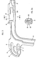
- FIG. 3 shows the rear, viewed in the direction of travel, of a pannier holder 2 which, at the connection point between the upper connection part 22 and the rear, slightly inclined connection part 24, has a projection with the two guides 6 and 7 projecting backwards as viewed in the direction of travel .
- the upper guide 6 has a part 61 which extends approximately horizontally in the extension of the upper connecting part 22 and which merges into a quarter circle 62 oriented downwards.
- the lower guide 7 is arranged at a predetermined distance from the horizontal part 61 of the upper guide and has only one horizontal part corresponding to this horizontal part 61.
- a pivot point 71 is indicated in FIG.
- the length of the lower guide 7 is dimensioned such that the conically tapering extension 342 at the front end 341 of the lower connecting part 34 of the frame parts 3 is sufficient for folding over the luggage rack 4 can be moved far (as seen in the direction of travel) to the rear.
- the receiving area 221 for the slotted and tapered extension 341 at the front end of the connecting part 34 of each frame part 3 is shown in plan view and in Figure 3a in a sectional view along the line A-A in Figure 3 in detail.
- the receiving area 221 has, as can be seen in particular from FIG. Seen in the direction of travel, an attachment with a bore 52 is shown behind the receiving area 221, into which a clip-in part is clipped, which is connected to the securing part by the plastic thread 51 (see FIG. 1).
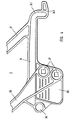
- FIG. 4 shows an enlarged representation of the lower connecting part 34 of a frame part 3.
- an extension 342 which is slit in the longitudinal direction and tapered towards the front (as seen in the direction of travel) is formed, which is offset with respect to the lower connecting part 34 and is arranged somewhat lower than the connecting part 34.
- the extension 35 is formed, which has an extension at its rear end with a bore 36, where a turn signal is fastened by means of a screw.
- two square holes 37 are formed, through which the fastening screws 38 are inserted, by means of which the frame part 3 is fastened to the respective pannier holder 2.
- a folded-up frame part 3 with the luggage rack 4 attached to it is pulled out in plan view shown. Furthermore, the folded-down frame part 3 with the luggage rack 4 is shown in broken lines in FIG. 2, the pivoting range of approximately 90 ° being indicated by a dashed quarter circle.
- the slotted, tapered extension 342 of each frame part 3 sits in the correspondingly designed recess 323 of the upper connecting part 22 of the respective pannier holder 2
- the conical design of the extension 342 and the recess 232 ensure good guiding and securing.
- the frame parts 3 can then be folded back together with the luggage rack 4 about the pivot point 71, in which case the shoulder 342 disengages from the insertion part 222 and the upper fastening screw 38 slides in the quarter circle 62 of the upper guide 6.
- the above-described processes and movements are carried out in the reverse order, so that after the insertion of the extension 342 into the insertion part 222 and after insertion of the extension 342 into the recess 223, only the four fastening screws 38 are now tightened firmly and that Security part 5 is to be introduced in the manner described.
- FIG. 5 schematically shows a part of a luggage rack 4 and the upper end of a frame part 3 with its connecting parts 31 to 33.
- three extension plates 43 are shown, each of which has two threaded holes 44. So that in a particularly wide rear section of a motorcycle, the mounting device 1 can be adapted accordingly, instead of the locking nuts used otherwise for fastening the frame parts, the extension plates 43 are inserted into the corresponding slots 42 and according to the required width of the mounting device by means of screws, not shown, in the luggage rack 4 secured.
- the frame parts 3 are then at the outer end of the connecting plate 43 fastened by inserting screws, not shown, through the guides 39 in the upper connecting part 33 and screwing them into the outer, threaded bores 44.
- the width of the mounting device 1 can additionally be varied in a range from 34 cm to 41 cm, as mentioned at the beginning.
Landscapes
- Engineering & Computer Science (AREA)
- Mechanical Engineering (AREA)
- Vehicle Step Arrangements And Article Storage (AREA)
- Purses, Travelling Bags, Baskets, Or Suitcases (AREA)
- Control Of Stepping Motors (AREA)
- Braking Arrangements (AREA)
- Control Of Eletrric Generators (AREA)
- Motorcycle And Bicycle Frame (AREA)
- Motor Or Generator Frames (AREA)
- Automatic Assembly (AREA)
- Steering Devices For Bicycles And Motorcycles (AREA)
Priority Applications (1)
| Application Number | Priority Date | Filing Date | Title |
|---|---|---|---|
| AT82105250T ATE19219T1 (de) | 1982-03-26 | 1982-06-15 | Halterungseinrichtung fuer motorraeder. |
Applications Claiming Priority (2)
| Application Number | Priority Date | Filing Date | Title |
|---|---|---|---|
| DE3211308 | 1982-03-26 | ||
| DE3211308A DE3211308C2 (de) | 1982-03-26 | 1982-03-26 | Das Hinterrad eines Motorrads umgreifende Halterungseinrichtung |
Publications (3)
| Publication Number | Publication Date |
|---|---|
| EP0090070A2 true EP0090070A2 (fr) | 1983-10-05 |
| EP0090070A3 EP0090070A3 (en) | 1984-09-05 |
| EP0090070B1 EP0090070B1 (fr) | 1986-04-16 |
Family
ID=6159458
Family Applications (1)
| Application Number | Title | Priority Date | Filing Date |
|---|---|---|---|
| EP82105250A Expired EP0090070B1 (fr) | 1982-03-26 | 1982-06-15 | Dispositif de fixation pour motocyclettes |
Country Status (8)
| Country | Link |
|---|---|
| US (1) | US4480773A (fr) |
| EP (1) | EP0090070B1 (fr) |
| JP (1) | JPS58167264A (fr) |
| AT (1) | ATE19219T1 (fr) |
| AU (1) | AU8885482A (fr) |
| DE (2) | DE3211308C2 (fr) |
| ES (1) | ES266889Y (fr) |
| ZA (1) | ZA825490B (fr) |
Cited By (2)
| Publication number | Priority date | Publication date | Assignee | Title |
|---|---|---|---|---|
| FR2612866A1 (fr) * | 1987-03-27 | 1988-09-30 | Schall Christian | Porte-bagages pour moto |
| WO2015135671A1 (fr) * | 2014-03-14 | 2015-09-17 | Bayerische Motoren Werke Aktiengesellschaft | Système porte-bagages pour deux-roues motorisé |
Families Citing this family (20)
| Publication number | Priority date | Publication date | Assignee | Title |
|---|---|---|---|---|
| DE3430427A1 (de) * | 1984-08-18 | 1986-02-27 | ESGE-MARBY GmbH + Co KG, 4800 Bielefeld | Vorderradseitengepaeckhalter |
| DE3612309A1 (de) * | 1986-04-11 | 1987-10-15 | Krauser Kraftfahrzeug Zubehoer | Das hinterrad eines motorrads umgreifende halterungseinrichtung fuer gepaeckstuecke, insbesondere motorradkoffer |
| JP2678603B2 (ja) * | 1987-10-03 | 1997-11-17 | 本田技研工業株式会社 | トランクを備えた自動二輪車 |
| TW265311B (fr) * | 1992-12-18 | 1995-12-11 | Suzuki Co Ltd | |
| US6016943A (en) | 1995-09-29 | 2000-01-25 | Polaris Industries Inc. | Injection molded racks and components for off-road recreational and utility vehicles |
| JPH11173334A (ja) * | 1997-10-06 | 1999-06-29 | Nippon Seiko Kk | 保持器付ころ軸受 |
| US6299042B1 (en) * | 2000-04-10 | 2001-10-09 | Charles E. Smith | Touring bag support for motorcycles |
| US6719179B1 (en) | 2001-09-27 | 2004-04-13 | Richard O. Webb, Jr. | Saddlebag protecting device |
| US6974007B2 (en) * | 2003-01-28 | 2005-12-13 | Raines Walter L | Motorcycle saddlebag protection apparatus and method |
| US8292139B2 (en) * | 2008-11-04 | 2012-10-23 | Trek Bicycle Corporation | Bicycle pannier mounting system |
| US20100282801A1 (en) * | 2009-05-05 | 2010-11-11 | John Willard | Collapsible Motorcycle Luggage Rack |
| US8162091B2 (en) * | 2009-08-31 | 2012-04-24 | Bombardier Recreational Products Inc. | System for mounting a box or bag to a vehicle |
| EP2684785B1 (fr) * | 2012-07-13 | 2015-11-04 | Thule IP AB | Dispositif de raccordement pour sacoche |
| US8985416B2 (en) | 2013-01-10 | 2015-03-24 | Harley-Davidson Motor Company Group, LLC | Mounting interface for a removable motorcycle accessory |
| JP6266408B2 (ja) * | 2014-03-31 | 2018-01-24 | 川崎重工業株式会社 | 自動二輪車のタンデムグリップ・ユニット |
| US10829056B2 (en) * | 2018-03-28 | 2020-11-10 | Gene's Machine, Inc. | Vehicle cargo securement system |
| IT201900008382A1 (it) * | 2019-06-07 | 2020-12-07 | Givi S P A | Kit di supporto e di inclinazione. |
| US11136085B2 (en) * | 2019-09-12 | 2021-10-05 | Christian K Hampton | Luggage rack wing |
| CN112455576B (zh) * | 2020-11-20 | 2021-12-28 | 广西上马科技有限公司 | 一种多功能智能感温型电动车后座 |
| US20240367743A1 (en) * | 2021-04-15 | 2024-11-07 | Bombardier Recreational Products Inc. | Stacking assembly and accessory stacking kit |
Family Cites Families (9)
| Publication number | Priority date | Publication date | Assignee | Title |
|---|---|---|---|---|
| DE8116262U1 (de) * | 1982-01-21 | Wolfgang Stengel GmbH, 6800 Mannheim | Motorradgepäckträger | |
| US1995980A (en) * | 1933-09-05 | 1935-03-26 | Haymond Earl | Clothes hanger support |
| DE1717143U (de) * | 1954-07-22 | 1956-02-16 | Malter & Co | Motorrad-koffertraeger mit gummirohrueberzug. |
| DE7707615U1 (de) * | 1977-03-11 | 1977-10-06 | Krauser Kraftfahrzeugzubehoer Vertriebs- Gmbh, 8905 Mering | Halterungseinrichtung fuer motorraeder |
| US4230245A (en) * | 1978-03-30 | 1980-10-28 | Juri Pold | Parcel carriers for motor cycles |
| US4257544A (en) * | 1979-05-09 | 1981-03-24 | Barry Dierkes | Detachable motorcycle rack |
| GB2066751A (en) * | 1980-01-04 | 1981-07-15 | Pulley Bros Ltd | Vehicle carriers |
| US4269335A (en) * | 1980-03-18 | 1981-05-26 | Triangle Accessoires De Motocyclettes Ltee. | Motorcycle luggage rack |
| US4349138A (en) * | 1981-10-19 | 1982-09-14 | Bruhn Andrew C | Carrying rack for motorcycles |
-
1982
- 1982-03-26 DE DE3211308A patent/DE3211308C2/de not_active Expired
- 1982-06-15 AT AT82105250T patent/ATE19219T1/de not_active IP Right Cessation
- 1982-06-15 DE DE8282105250T patent/DE3270586D1/de not_active Expired
- 1982-06-15 EP EP82105250A patent/EP0090070B1/fr not_active Expired
- 1982-07-30 ZA ZA825490A patent/ZA825490B/xx unknown
- 1982-08-11 ES ES1982266889U patent/ES266889Y/es not_active Expired
- 1982-08-23 US US06/410,821 patent/US4480773A/en not_active Expired - Fee Related
- 1982-09-24 JP JP57166422A patent/JPS58167264A/ja active Granted
- 1982-09-29 AU AU88854/82A patent/AU8885482A/en not_active Abandoned
Cited By (2)
| Publication number | Priority date | Publication date | Assignee | Title |
|---|---|---|---|---|
| FR2612866A1 (fr) * | 1987-03-27 | 1988-09-30 | Schall Christian | Porte-bagages pour moto |
| WO2015135671A1 (fr) * | 2014-03-14 | 2015-09-17 | Bayerische Motoren Werke Aktiengesellschaft | Système porte-bagages pour deux-roues motorisé |
Also Published As
| Publication number | Publication date |
|---|---|
| ZA825490B (en) | 1983-06-29 |
| ATE19219T1 (de) | 1986-05-15 |
| ES266889U (es) | 1983-03-01 |
| JPS6243903B2 (fr) | 1987-09-17 |
| EP0090070A3 (en) | 1984-09-05 |
| DE3211308A1 (de) | 1983-10-13 |
| EP0090070B1 (fr) | 1986-04-16 |
| JPS58167264A (ja) | 1983-10-03 |
| DE3211308C2 (de) | 1986-08-28 |
| AU8885482A (en) | 1983-09-29 |
| ES266889Y (es) | 1983-09-01 |
| DE3270586D1 (en) | 1986-05-22 |
| US4480773A (en) | 1984-11-06 |
Similar Documents
| Publication | Publication Date | Title |
|---|---|---|
| EP0090070B1 (fr) | Dispositif de fixation pour motocyclettes | |
| DE19833708A1 (de) | Höhenverstellbares Hängesystem mit Diebstahlsicherung | |
| DE2921703A1 (de) | Transportvorrichtung zur befestigung auf einem autodach | |
| DE2508217C3 (de) | Gepäckträger | |
| EP0245541A2 (fr) | Dispositif de montage en une pièce fixable au cadre d'une motocyclette | |
| EP0049904A2 (fr) | Fixation pour cadenas à anses longues | |
| DE2836311C2 (de) | Dachträger für Kraftfahrzeuge | |
| DE19521083B4 (de) | Mittel zur Befestigung von Behältnissen an Fahrrädern und Behältnis mit den Befestigungsmitteln | |
| DE4029012A1 (de) | Fahrrad, abnehmbares bauteil eines fahrrades und zubehoer fuer ein zweirad | |
| DE202016003201U1 (de) | Gepäckträger für ein Kraftfahrzeug, welches ein Fahrzeuggestell, einen Lenker und einen Sattel/Sitz umfasst, und, in welchem ein Raum zwischen dem Lenker und dem Sattel/Sitz definiert ist | |
| DE9410306U1 (de) | Motorrad nach Art eines Motorrollers o.dgl. mit zusammenfaltbarer Regenschutzeinrichtung | |
| DE3529912C1 (de) | Kraftfahrzeug mit Leuchtenschutzvorrichtung | |
| DE8208746U1 (de) | Halterungseinrichtung fuer motorraeder | |
| DE202020102320U1 (de) | Sattelhalterung | |
| DE3249434C2 (de) | Das Hinterrad eines Motorrads umgreifende Halterungseinrichtung für Gepäckstücke | |
| DE7707615U1 (de) | Halterungseinrichtung fuer motorraeder | |
| DE8315720U1 (de) | Behaelter, insbesondere fuer die festlegung an einem fahrzeug | |
| WO1994011234A1 (fr) | Dispositif a fixer sur le cadre d'un vehicule a deux roues | |
| DE9413049U1 (de) | Vorrichtung zum Befestigen einer Abdeckleiste für Nuten von Kraftwagen-Aufbauten | |
| DE3324971C2 (de) | Anhänger für ein Zweirad | |
| DE9108285U1 (de) | Halterungseinrichtung zur Halterung eines Fahrradzubehörteils | |
| DE8531937U1 (de) | Halterungsvorrichtung zum Anbringen eines zusätzlichen Spiegels an einem Außenspiegel-Gehäuse eines Kraftfahrzeugs | |
| DE20201646U1 (de) | Halterung für ein Fahrrad | |
| EP0240612A2 (fr) | Dispositif de montage pour bagages qui entoure la roue arrière d'une motocyclette, plus particulièrement pour valises | |
| DE3612310A1 (de) | Das hinterrad eines motorrads umgreifende halterungseinrichtung |
Legal Events
| Date | Code | Title | Description |
|---|---|---|---|
| PUAI | Public reference made under article 153(3) epc to a published international application that has entered the european phase |
Free format text: ORIGINAL CODE: 0009012 |
|
| AK | Designated contracting states |
Designated state(s): AT BE CH DE FR GB IT LI LU NL SE |
|
| PUAL | Search report despatched |
Free format text: ORIGINAL CODE: 0009013 |
|
| AK | Designated contracting states |
Designated state(s): AT BE CH DE FR GB IT LI LU NL SE |
|
| 17P | Request for examination filed |
Effective date: 19841116 |
|
| GRAA | (expected) grant |
Free format text: ORIGINAL CODE: 0009210 |
|
| AK | Designated contracting states |
Kind code of ref document: B1 Designated state(s): AT BE CH DE FR GB IT LI LU NL SE |
|
| REF | Corresponds to: |
Ref document number: 19219 Country of ref document: AT Date of ref document: 19860515 Kind code of ref document: T |
|
| ITF | It: translation for a ep patent filed | ||
| REF | Corresponds to: |
Ref document number: 3270586 Country of ref document: DE Date of ref document: 19860522 |
|
| PGFP | Annual fee paid to national office [announced via postgrant information from national office to epo] |
Ref country code: AT Payment date: 19860626 Year of fee payment: 5 |
|
| PG25 | Lapsed in a contracting state [announced via postgrant information from national office to epo] |
Ref country code: LU Free format text: LAPSE BECAUSE OF NON-PAYMENT OF DUE FEES Effective date: 19860630 |
|
| ET | Fr: translation filed | ||
| PLBE | No opposition filed within time limit |
Free format text: ORIGINAL CODE: 0009261 |
|
| STAA | Information on the status of an ep patent application or granted ep patent |
Free format text: STATUS: NO OPPOSITION FILED WITHIN TIME LIMIT |
|
| 26N | No opposition filed | ||
| PGFP | Annual fee paid to national office [announced via postgrant information from national office to epo] |
Ref country code: NL Payment date: 19870630 Year of fee payment: 6 |
|
| PG25 | Lapsed in a contracting state [announced via postgrant information from national office to epo] |
Ref country code: GB Effective date: 19880615 Ref country code: AT Effective date: 19880615 |
|
| PG25 | Lapsed in a contracting state [announced via postgrant information from national office to epo] |
Ref country code: SE Effective date: 19880616 |
|
| PG25 | Lapsed in a contracting state [announced via postgrant information from national office to epo] |
Ref country code: LI Effective date: 19880630 Ref country code: CH Effective date: 19880630 |
|
| BERE | Be: lapsed |
Owner name: KRAUSER KRAFTFAHRZEUG-ZUBEHOR VERTRIEBS-G.M.B.H. Effective date: 19880630 |
|
| PG25 | Lapsed in a contracting state [announced via postgrant information from national office to epo] |
Ref country code: NL Effective date: 19890101 |
|
| NLV4 | Nl: lapsed or anulled due to non-payment of the annual fee | ||
| GBPC | Gb: european patent ceased through non-payment of renewal fee | ||
| PG25 | Lapsed in a contracting state [announced via postgrant information from national office to epo] |
Ref country code: FR Free format text: LAPSE BECAUSE OF NON-PAYMENT OF DUE FEES Effective date: 19890228 |
|
| REG | Reference to a national code |
Ref country code: CH Ref legal event code: PL |
|
| PG25 | Lapsed in a contracting state [announced via postgrant information from national office to epo] |
Ref country code: DE Effective date: 19890301 |
|
| REG | Reference to a national code |
Ref country code: FR Ref legal event code: ST |
|
| PG25 | Lapsed in a contracting state [announced via postgrant information from national office to epo] |
Ref country code: BE Effective date: 19890630 |
|
| EUG | Se: european patent has lapsed |
Ref document number: 82105250.3 Effective date: 19890220 |