EP0090132A1 - Distributeur de liquide pour un laveur à garnissage - Google Patents
Distributeur de liquide pour un laveur à garnissage Download PDFInfo
- Publication number
- EP0090132A1 EP0090132A1 EP83100467A EP83100467A EP0090132A1 EP 0090132 A1 EP0090132 A1 EP 0090132A1 EP 83100467 A EP83100467 A EP 83100467A EP 83100467 A EP83100467 A EP 83100467A EP 0090132 A1 EP0090132 A1 EP 0090132A1
- Authority
- EP
- European Patent Office
- Prior art keywords
- pipes
- parallel
- diamond
- feed
- liquid
- Prior art date
- Legal status (The legal status is an assumption and is not a legal conclusion. Google has not performed a legal analysis and makes no representation as to the accuracy of the status listed.)
- Withdrawn
Links
Images





Classifications
-
- B—PERFORMING OPERATIONS; TRANSPORTING
- B01—PHYSICAL OR CHEMICAL PROCESSES OR APPARATUS IN GENERAL
- B01D—SEPARATION
- B01D53/00—Separation of gases or vapours; Recovering vapours of volatile solvents from gases; Chemical or biological purification of waste gases, e.g. engine exhaust gases, smoke, fumes, flue gases, aerosols
- B01D53/14—Separation of gases or vapours; Recovering vapours of volatile solvents from gases; Chemical or biological purification of waste gases, e.g. engine exhaust gases, smoke, fumes, flue gases, aerosols by absorption
- B01D53/18—Absorbing units; Liquid distributors therefor
- B01D53/185—Liquid distributors
-
- F—MECHANICAL ENGINEERING; LIGHTING; HEATING; WEAPONS; BLASTING
- F28—HEAT EXCHANGE IN GENERAL
- F28F—DETAILS OF HEAT-EXCHANGE AND HEAT-TRANSFER APPARATUS, OF GENERAL APPLICATION
- F28F25/00—Component parts of trickle coolers
- F28F25/02—Component parts of trickle coolers for distributing, circulating, and accumulating liquid
- F28F25/04—Distributing or accumulator troughs
Definitions
- the invention relates to a Device for sprinkling a packed bed with a liquid in a cylindrical packed tower for a heat and mass transfer taking place between a gas and a liquid, which is arranged above or inside or partly inside the bed and which consists of feed pipes and distributor pipes provided with through-openings, the Feed pipes are connected to the distribution pipes on the liquid side.
- the packed bed For a heat and mass exchange taking place between a gas and a liquid, the packed bed not only has the task of forming a large exchange area, but also to distribute the liquid evenly within the bed. Since the latter has an influence on the height of the bed, efforts are being made to achieve a uniform distribution of the liquid as soon as it enters the packing bed by means of suitable sprinkling devices.
- Nozzle distributor systems show no material stability over a long period of time and no permanent nozzle characteristics, because due to the increased speed in the nozzle outlet, abrasive and chemical corrosion occur more frequently.
- the sprinkling liquid is supplied via a feed pipe to a large number of distributor pipes arranged in parallel.
- the parallel arrangement of the distributor pipes in the circular cross-sectional area of a packed tower results in different pipe lengths. Assuming the same diameter of the distributor pipes, different flow speeds occur in the individual pipes of different lengths, which leads to different pressure losses and ultimately to an uneven distribution of the amount of the sprinkling liquid.
- the present invention has for its object to provide a device for sprinkling packings in packing towers, which ensures a uniform distribution of the sprinkling liquid with entry into the packing.
- a feed pipe is arranged with associated mutually equal distribution pipes, the longitudinal axis of each supply pipe parallel to a diamond-delimiting section and the Longitudinal axis of the distribution pipes are parallel to the other non-parallel diamond-delimiting section.
- the longitudinal axes of all the distribution pipes lie above or below or at the same height as the longitudinal axes of the supply pipes and that two or more parallel supply pipes are arranged in an imaginary diamond surface.
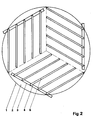
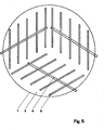
- FIG. 1 in the free cross-sectional plane, which - not shown in more detail - is located above or inside or partially within a packed bed 2 of a cylindrical packed tower 1, three largest equally sized imaginary diamond surfaces 3 are arranged, the sum of which forms a cross-sectional-inscribed hexagon.
- a feed pipe 4 parallel to these lines which is connected in terms of line to a ring pipeline, not shown, outside the cylindrical jacket of the packing tower 1, via which the supply of sprinkling liquid takes place.
- the feed pipe 4 is connected on the liquid side to manifolds 5 of equal length, the longitudinal axes of which lie within the imaginary diamond surface 3 parallel to the other diamond-delimiting paths that are not parallel to the feed pipe and at the same height as the longitudinal axes of the feed pipes 4.
- manifolds 5 of equal length, the longitudinal axes of which lie within the imaginary diamond surface 3 parallel to the other diamond-delimiting paths that are not parallel to the feed pipe and at the same height as the longitudinal axes of the feed pipes 4.
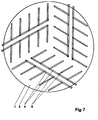
- the longitudinal axis of the feed pipe 4 can lie either in the radial diamond-delimiting section (FIG. 3) or in the radial, parallel diamond-delimiting section (FIG. 2), or also parallel and arbitrarily between the two parallel diamond-delimiting sections.
- the irrigation liquid is not supplied via a ring line but via a line located in the tower axis.
- FIG. 1, 2 The longitudinal axes of the three feed tubes are shown in FIG. 1, 2 are disposed, 3 and 4 to each other offset by an angle of 12 0 °.
- a parallel arrangement in the sense of the solutions shown in FIGS. 1 to 3 can also be selected for two or three feed pipes 4.
- two or three parallel feed tubes can be assigned to each imaginary diamond surface.
- the individual distributor pipes are provided in a known manner with several slot-like passage openings arranged at certain intervals with a view to an optimal packing irrigation, whereby a passage opening at the lowest level point of each distributor pipe should allow the discharge of solid particles with the sprinkling liquid.
- the dimensions of the distances, the number and the size of the passage openings are such that the outlet velocity of the serial fluid is 2 to 3 times, but at least 1.5 times the flow velocity in the distributor pipe 5.
Landscapes
- Engineering & Computer Science (AREA)
- Chemical & Material Sciences (AREA)
- Analytical Chemistry (AREA)
- Mechanical Engineering (AREA)
- General Engineering & Computer Science (AREA)
- Thermal Sciences (AREA)
- Physics & Mathematics (AREA)
- General Chemical & Material Sciences (AREA)
- Oil, Petroleum & Natural Gas (AREA)
- Chemical Kinetics & Catalysis (AREA)
- Feeding, Discharge, Calcimining, Fusing, And Gas-Generation Devices (AREA)
- Vaporization, Distillation, Condensation, Sublimation, And Cold Traps (AREA)
- Physical Or Chemical Processes And Apparatus (AREA)
- Gas Separation By Absorption (AREA)
Applications Claiming Priority (2)
| Application Number | Priority Date | Filing Date | Title |
|---|---|---|---|
| DE3211885A DE3211885C2 (de) | 1982-03-31 | 1982-03-31 | Flüssigkeitsverteiler für einen zylindrischen Füllkörperturm |
| DE3211885 | 1982-03-31 |
Publications (1)
| Publication Number | Publication Date |
|---|---|
| EP0090132A1 true EP0090132A1 (fr) | 1983-10-05 |
Family
ID=6159820
Family Applications (1)
| Application Number | Title | Priority Date | Filing Date |
|---|---|---|---|
| EP83100467A Withdrawn EP0090132A1 (fr) | 1982-03-31 | 1983-01-20 | Distributeur de liquide pour un laveur à garnissage |
Country Status (4)
| Country | Link |
|---|---|
| EP (1) | EP0090132A1 (fr) |
| DE (1) | DE3211885C2 (fr) |
| ES (1) | ES279831Y (fr) |
| FI (1) | FI830953L (fr) |
Cited By (2)
| Publication number | Priority date | Publication date | Assignee | Title |
|---|---|---|---|---|
| EP0524729A1 (fr) * | 1991-07-26 | 1993-01-27 | The Babcock & Wilcox Company | Appareil de pulvérisation à étages et méthodes de désulfuration de gaz de fumées |
| CN109647143A (zh) * | 2018-11-29 | 2019-04-19 | 何爱建 | 一种冷轧钢加工生产用的移动碱雾吸收装置 |
Citations (2)
| Publication number | Priority date | Publication date | Assignee | Title |
|---|---|---|---|---|
| FR703029A (fr) * | 1930-09-24 | 1931-04-22 | Dispositif d'arrosage pour tours d'absorption, de lavage et analogues | |
| DE2849350A1 (de) * | 1978-11-14 | 1980-05-29 | Biprokwas | Berieselungsvorrichtung fuer absorptionstuerme |
Family Cites Families (1)
| Publication number | Priority date | Publication date | Assignee | Title |
|---|---|---|---|---|
| US3392966A (en) * | 1966-07-28 | 1968-07-16 | Us Stoneware Inc | Treating tower inductor |
-
1982
- 1982-03-31 DE DE3211885A patent/DE3211885C2/de not_active Expired
-
1983
- 1983-01-20 EP EP83100467A patent/EP0090132A1/fr not_active Withdrawn
- 1983-03-15 ES ES1983279831U patent/ES279831Y/es not_active Expired
- 1983-03-22 FI FI830953A patent/FI830953L/fi not_active Application Discontinuation
Patent Citations (2)
| Publication number | Priority date | Publication date | Assignee | Title |
|---|---|---|---|---|
| FR703029A (fr) * | 1930-09-24 | 1931-04-22 | Dispositif d'arrosage pour tours d'absorption, de lavage et analogues | |
| DE2849350A1 (de) * | 1978-11-14 | 1980-05-29 | Biprokwas | Berieselungsvorrichtung fuer absorptionstuerme |
Cited By (3)
| Publication number | Priority date | Publication date | Assignee | Title |
|---|---|---|---|---|
| EP0524729A1 (fr) * | 1991-07-26 | 1993-01-27 | The Babcock & Wilcox Company | Appareil de pulvérisation à étages et méthodes de désulfuration de gaz de fumées |
| TR26930A (tr) * | 1991-07-26 | 1994-08-24 | Babcock & Wilcox Co | Baca gazinin sülfürünün giderilmesi icin tek püskürtmeli sistem. |
| CN109647143A (zh) * | 2018-11-29 | 2019-04-19 | 何爱建 | 一种冷轧钢加工生产用的移动碱雾吸收装置 |
Also Published As
| Publication number | Publication date |
|---|---|
| DE3211885C2 (de) | 1985-01-03 |
| DE3211885A1 (de) | 1983-10-13 |
| FI830953A7 (fi) | 1983-10-01 |
| FI830953L (fi) | 1983-10-01 |
| ES279831Y (es) | 1985-07-01 |
| FI830953A0 (fi) | 1983-03-22 |
| ES279831U (es) | 1985-01-01 |
Similar Documents
| Publication | Publication Date | Title |
|---|---|---|
| DE2919462C2 (de) | Vorrichtung zum gleichmäßigen Verteilen von Flüssigkeiten auf Kolonnenflächen | |
| DE69222482T2 (de) | Vorrichtung und Verfahren zur Rauchgasentschwefelung | |
| DE3118777C2 (de) | Vorrichtung zur Flüssigkeitsverteilung in Filmform in Vertikalrohren | |
| DD158941A5 (de) | Fluessigkeitsverteiler fuer fallfilm-waermeaustauscher | |
| EP0090132A1 (fr) | Distributeur de liquide pour un laveur à garnissage | |
| DE1906772B2 (de) | Spruehdose | |
| DE8209180U1 (de) | Fluessigkeitsverteiler fuer einen fuellkoerperturm | |
| DE2836113A1 (de) | Spritzsystem fuer verteilung von fluessigkeit, insbesondere fuer biofilterbetten, kuehltuerme u.dgl. | |
| DE1131603B (de) | Vorrichtung zum gleichmaessigen Verteilen von Fluessigkeiten ueber kreisbegrenzte Flaechen | |
| DE3610533C2 (fr) | ||
| DE2320630A1 (de) | Vorrichtung zur tropfenweisen berieselung | |
| DE4001013C2 (fr) | ||
| DE3145573C2 (de) | Massenstromverteileinrichtung zum Aufteilen eines Wasser-Dampf-Gemisches | |
| AT301460B (de) | Düse, insbesondere für Wasseraufbereitungsanlagen | |
| EP0898489A1 (fr) | Dispositif pour distribuer du liquide dans des colonnes d'echange de substances | |
| DE202017105557U1 (de) | Berieselungssystem | |
| DD229774A1 (de) | Rohrbuendelwaermeuebertrager horizontaler bauart mit berieselungseinrichtung oberhalb des rohrbuendels | |
| DE2904440A1 (de) | Fluessigkeitsleitende vorrichtung | |
| DE922639C (de) | Fluessigkeitsverteiler mit mehreren Dueseneinsaetzen | |
| DE4337981B4 (de) | Stoffaustauschboden mit einem Flüssigkeitsverteiler | |
| DE1621566C3 (de) | Vorrichtung zum Verdüsen von Antikorrosionsflüssigkeit in Brenngas-Versorgungs-Niederdruckleitungen | |
| DE507115C (de) | Kristallisationsapparat | |
| DE1245869B (de) | Abwasser-Drehsprenger fuer biologische Tropfkoerper mit wechselndem Zufluss | |
| AT88371B (de) | Vorrichtung zur Behandlung von Gasen oder Dämpfen mit Flüssigkeiten in feinst verteiltem Zustande. | |
| DE971625C (de) | Fuellkoerpersaeule |
Legal Events
| Date | Code | Title | Description |
|---|---|---|---|
| PUAI | Public reference made under article 153(3) epc to a published international application that has entered the european phase |
Free format text: ORIGINAL CODE: 0009012 |
|
| 17P | Request for examination filed |
Effective date: 19830214 |
|
| AK | Designated contracting states |
Designated state(s): BE FR IT NL SE |
|
| STAA | Information on the status of an ep patent application or granted ep patent |
Free format text: STATUS: THE APPLICATION IS DEEMED TO BE WITHDRAWN |
|
| 18D | Application deemed to be withdrawn |
Effective date: 19860801 |
|
| RIN1 | Information on inventor provided before grant (corrected) |
Inventor name: SEIDLER, WILLI |