EP0524729A1 - Appareil de pulvérisation à étages et méthodes de désulfuration de gaz de fumées - Google Patents
Appareil de pulvérisation à étages et méthodes de désulfuration de gaz de fumées Download PDFInfo
- Publication number
- EP0524729A1 EP0524729A1 EP92305852A EP92305852A EP0524729A1 EP 0524729 A1 EP0524729 A1 EP 0524729A1 EP 92305852 A EP92305852 A EP 92305852A EP 92305852 A EP92305852 A EP 92305852A EP 0524729 A1 EP0524729 A1 EP 0524729A1
- Authority
- EP
- European Patent Office
- Prior art keywords
- headers
- tower
- flue gas
- spray
- header
- Prior art date
- Legal status (The legal status is an assumption and is not a legal conclusion. Google has not performed a legal analysis and makes no representation as to the accuracy of the status listed.)
- Granted
Links
- 239000007921 spray Substances 0.000 title claims abstract description 60
- UGFAIRIUMAVXCW-UHFFFAOYSA-N Carbon monoxide Chemical compound [O+]#[C-] UGFAIRIUMAVXCW-UHFFFAOYSA-N 0.000 title claims abstract description 38
- 239000003546 flue gas Substances 0.000 title claims abstract description 38
- 238000000034 method Methods 0.000 title claims description 7
- 239000006096 absorbing agent Substances 0.000 claims abstract description 40
- 239000007789 gas Substances 0.000 claims description 7
- 238000005507 spraying Methods 0.000 claims description 5
- 239000012530 fluid Substances 0.000 claims description 2
- 239000000203 mixture Substances 0.000 abstract description 7
- NINIDFKCEFEMDL-UHFFFAOYSA-N Sulfur Chemical compound [S] NINIDFKCEFEMDL-UHFFFAOYSA-N 0.000 description 7
- 239000005864 Sulphur Substances 0.000 description 7
- RAHZWNYVWXNFOC-UHFFFAOYSA-N Sulphur dioxide Chemical compound O=S=O RAHZWNYVWXNFOC-UHFFFAOYSA-N 0.000 description 6
- 239000007788 liquid Substances 0.000 description 4
- 238000005086 pumping Methods 0.000 description 4
- 235000019738 Limestone Nutrition 0.000 description 3
- 238000010276 construction Methods 0.000 description 3
- 239000006028 limestone Substances 0.000 description 3
- 235000010269 sulphur dioxide Nutrition 0.000 description 3
- 239000004291 sulphur dioxide Substances 0.000 description 3
- 235000008733 Citrus aurantifolia Nutrition 0.000 description 2
- FYYHWMGAXLPEAU-UHFFFAOYSA-N Magnesium Chemical compound [Mg] FYYHWMGAXLPEAU-UHFFFAOYSA-N 0.000 description 2
- 235000011941 Tilia x europaea Nutrition 0.000 description 2
- 239000003153 chemical reaction reagent Substances 0.000 description 2
- 238000010586 diagram Methods 0.000 description 2
- 239000004571 lime Substances 0.000 description 2
- 239000011777 magnesium Substances 0.000 description 2
- 229910052749 magnesium Inorganic materials 0.000 description 2
- 239000000463 material Substances 0.000 description 2
- VEXZGXHMUGYJMC-UHFFFAOYSA-M Chloride anion Chemical compound [Cl-] VEXZGXHMUGYJMC-UHFFFAOYSA-M 0.000 description 1
- DGAQECJNVWCQMB-PUAWFVPOSA-M Ilexoside XXIX Chemical compound C[C@@H]1CC[C@@]2(CC[C@@]3(C(=CC[C@H]4[C@]3(CC[C@@H]5[C@@]4(CC[C@@H](C5(C)C)OS(=O)(=O)[O-])C)C)[C@@H]2[C@]1(C)O)C)C(=O)O[C@H]6[C@@H]([C@H]([C@@H]([C@H](O6)CO)O)O)O.[Na+] DGAQECJNVWCQMB-PUAWFVPOSA-M 0.000 description 1
- 239000003513 alkali Substances 0.000 description 1
- 230000009977 dual effect Effects 0.000 description 1
- 230000003647 oxidation Effects 0.000 description 1
- 238000007254 oxidation reaction Methods 0.000 description 1
- 239000002245 particle Substances 0.000 description 1
- 230000035515 penetration Effects 0.000 description 1
- 238000010791 quenching Methods 0.000 description 1
- 230000009257 reactivity Effects 0.000 description 1
- 230000000717 retained effect Effects 0.000 description 1
- 239000011734 sodium Substances 0.000 description 1
- 229910052708 sodium Inorganic materials 0.000 description 1
- 239000007787 solid Substances 0.000 description 1
Images


Classifications
-
- B—PERFORMING OPERATIONS; TRANSPORTING
- B01—PHYSICAL OR CHEMICAL PROCESSES OR APPARATUS IN GENERAL
- B01D—SEPARATION
- B01D53/00—Separation of gases or vapours; Recovering vapours of volatile solvents from gases; Chemical or biological purification of waste gases, e.g. engine exhaust gases, smoke, fumes, flue gases, aerosols
- B01D53/34—Chemical or biological purification of waste gases
- B01D53/46—Removing components of defined structure
- B01D53/48—Sulfur compounds
- B01D53/50—Sulfur oxides
- B01D53/501—Sulfur oxides by treating the gases with a solution or a suspension of an alkali or earth-alkali or ammonium compound
- B01D53/504—Sulfur oxides by treating the gases with a solution or a suspension of an alkali or earth-alkali or ammonium compound characterised by a specific device
-
- B—PERFORMING OPERATIONS; TRANSPORTING
- B01—PHYSICAL OR CHEMICAL PROCESSES OR APPARATUS IN GENERAL
- B01D—SEPARATION
- B01D47/00—Separating dispersed particles from gases, air or vapours by liquid as separating agent
- B01D47/06—Spray cleaning
-
- B—PERFORMING OPERATIONS; TRANSPORTING
- B01—PHYSICAL OR CHEMICAL PROCESSES OR APPARATUS IN GENERAL
- B01D—SEPARATION
- B01D53/00—Separation of gases or vapours; Recovering vapours of volatile solvents from gases; Chemical or biological purification of waste gases, e.g. engine exhaust gases, smoke, fumes, flue gases, aerosols
- B01D53/14—Separation of gases or vapours; Recovering vapours of volatile solvents from gases; Chemical or biological purification of waste gases, e.g. engine exhaust gases, smoke, fumes, flue gases, aerosols by absorption
- B01D53/18—Absorbing units; Liquid distributors therefor
-
- B—PERFORMING OPERATIONS; TRANSPORTING
- B01—PHYSICAL OR CHEMICAL PROCESSES OR APPARATUS IN GENERAL
- B01D—SEPARATION
- B01D53/00—Separation of gases or vapours; Recovering vapours of volatile solvents from gases; Chemical or biological purification of waste gases, e.g. engine exhaust gases, smoke, fumes, flue gases, aerosols
- B01D53/34—Chemical or biological purification of waste gases
- B01D53/74—General processes for purification of waste gases; Apparatus or devices specially adapted therefor
-
- B—PERFORMING OPERATIONS; TRANSPORTING
- B01—PHYSICAL OR CHEMICAL PROCESSES OR APPARATUS IN GENERAL
- B01D—SEPARATION
- B01D53/00—Separation of gases or vapours; Recovering vapours of volatile solvents from gases; Chemical or biological purification of waste gases, e.g. engine exhaust gases, smoke, fumes, flue gases, aerosols
- B01D53/34—Chemical or biological purification of waste gases
- B01D53/74—General processes for purification of waste gases; Apparatus or devices specially adapted therefor
- B01D53/77—Liquid phase processes
- B01D53/78—Liquid phase processes with gas-liquid contact
-
- H—ELECTRICITY
- H10—SEMICONDUCTOR DEVICES; ELECTRIC SOLID-STATE DEVICES NOT OTHERWISE PROVIDED FOR
- H10N—ELECTRIC SOLID-STATE DEVICES NOT OTHERWISE PROVIDED FOR
- H10N60/00—Superconducting devices
- H10N60/20—Permanent superconducting devices
Definitions
- This invention relates to flue gas desulphurisation, and more particularly to spray level apparatus and methods for this purpose.
- Flue gas desulphurisation occurs primarily in flue gas absorber towers by means of spraying the flue gas with a mixture which causes the sulphur to precipitate out. This spraying is accomplished by installing spray headers across the tower opening directly in the flue gas path. In early systems which were typically comparatively small, a single spray level was all that was needed because of the low flue gas flow rates. However, as systems became larger, the flue gas flow rates increased and the spray volume was increased up to pump capacity until additional spray levels were required.
- each level increases the absorber tower height by up to 1.5 m (5 ft) or more and this can be critical in closely confined quarters.
- the ultimate need is dictated by the flue gas flow rate and the desire to remove as much sulphur as possible before releasing these gases to the atmosphere.
- a FGD system it has become quite common for a FGD system to incorporate five or more spray levels to accommodate the flue gas volume and sulphur density.
- the absorber tower to be raised in height by about 6 m (20 ft) or more with these multiple spray levels requiring a corresponding increase in pumping and piping requirements.
- the tower height (as well as diameter) had to be increased which required more pumping power.
- the FGD system incorporates a high liquid to gas (L/G) ratio as compared to the more common use of low ratios in other systems.
- the L/G ratio is a reference to liquid flow rate relative to gas volume whose units are gallon per minute per 1000 actual cubic feet per minute (gpm/macfm), each such unit being equivalent to 1.34 x 10 ⁇ 4 cubic metres per minute/cubic metres per minute.
- This L/G ratio is determined by a number of process variables including reagent type, pH, solids particle size, reactivity, chloride ion concentration, sulphur dioxide concentration, sulphur dioxide removal, reagent utilisation, spray drop size, and the like.
- a high L/G ratio implies a high liquid flow rate relative to gas volume which is typically a value of 40 to 140 or more. Consequently, a low L/G ratio would generally be a value of less than 20.
- One way of accomplishing a high L/G ratio is by simply adding more spray levels to the absorber tower so that more of the mixture can be sprayed on to the flue gas. This, however, does not eliminate the need for a taller tower nor does it diminish the need for more pumping power so that the mixture can be delivered at the higher elevation.
- spray level apparatus for a flue gas desulphurisation absorber tower, the apparatus comprising: at least two elongate headers secured adjacent the tower; a plurality of elongate feeder lines secured to each header, the feeder lines from the headers being staggered so as to extend alternately across the flue gas flow path in at least substantially the same plane within the tower; and a plurality of nozzles secured to each feeder line, the nozzles being configured so as to spray on to the flue gas within the tower.
- a method of spraying flue gas in a flue gas desulphurisation absorber tower comprising the steps of: securing at least two elongate headers to the tower; attaching multiple elongate feeder lines to each header, the feeder lines from each header being staggered so as to extend alternately across the flue gas flow path in at least substantially the same plane within the tower; and securing a series of nozzles to each feeder line, the nozzles being configured so as to spray upon the flue gas within the tower.
- This invention further provides a spray level for a flue gas desulphurisation absorber tower, comprising one or more headers secured adjacent the tower, a plurality of elongate feeder lines secured to each of the headers with the feeder lines from each header being staggered with respect to each other so as to extend alternately across the flue gas flow path, the feeder lines also extending in the same, or nearly the same, plane within the tower, and multiple nozzles secured to each of the feeder lines, the nozzles being configured to spray on to the flue gas within the tower.
- Embodiments of this invention provide a system that both reduces absorber tower height and lowers energy costs; the preferred FGD system can incorporate a spare spray without also increasing absorber tower height.
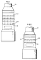
- FIG. 1 there is shown a typical absorber tower 10 for a 500 MW flue gas desulphurisation system.
- This typical tower extends about 36.9 m (121 ft) above the ground and is about 18.3 m (60 ft) in diameter. It encloses multiple spray levels 12 with each such level 12 usually being a duplicate of the one above and below it and with about 1.5 m (5 ft) of space between each level.
- the multiple levels 12 were needed so that the entire area of the absorber tower 10 could be covered by the spray and so that the liquid to gas flow rate (L/G) necessary to cause the desired sulphur dioxide capture could be delivered by independent large capacity pumps. It is this spray that causes the sulphur in the flue gas to fall out, thus the requirement that the spray be in contact with all of the flue gas for the system to work.
- Figure 2 shows an embodiment of the present invention which only requires a single spray level 12 for operation.
- the single spray level 12 requires a structure that is also about 18.3 m (60 ft) in diameter but which extends only about 29.6 m (97 ft) above the ground, representing a saving of about 7.3 m (24 ft) in absorber tower height.
- the design of this embodiment can still accomplish the objective of spraying the entire flue gas for sulphur removal whilst also incorporating spare spray capacity should this be needed.
- the single spray level 12 consists of four separate external elongate headers 14 each having a number of parallel feeder lines 16 connected thereto, the feeder lines 16 having nozzles 20 (only some of which are shown in Figure 3). These individual feeder lines 16 are reduced or become smaller in diameter the further they extend from their respective header 14 (see Figure 4).
- This reduction is to compensate for the drop in fluid flow that occurs in each feeder line 16 as it extends across the absorber tower 10.
- the purpose here is to maintain as constant a pressure as possible along the length of each feeder line 16 and to maintain reasonable line velocities.
- each header 14 becomes smaller in diameter along its length for similar reasons.
- this embodiment encompasses two headers 14 on each of the opposite sides of the absorber tower 10, there accordingly being a total of four such headers 14 in this embodiment.
- the opposite sides of the arrangement are essentially mirror images (basically the same but rotated through 180 degrees) of each other.
- Each header pair on the same side of the absorber tower 10 is vertically, and in certain embodiments horizontally, spaced a slight distance from the other. This is so that the feeder lines 16 from that side (and preferably from both sides) will extend in the same plane within the absorber tower 10.
- a lower header 14 lies in the desired plane whilst an upper header 14 is both horizontally and vertically offset from the lower header 14.
- the plane of the feeder lines 16 lies between both the headers 14 thereby requiring each feeder line to be oriented accordingly.
- the feeder lines 16 are constructed to extend within the same plane (be coplanar) within the absorber tower 10 as shown in Figure 5.
- the design of the FGD system will determine the number of pumps and headers 14 required.
- the combination shown is for two headers 14 per side.
- Other possible combinations include two headers 14 on one side and one on the other, or three on one side and none on the other, or any other combination of from zero to four headers 14 on each of the opposite sides of the tower 10 (as long as at least two headers 14 are included in the overall system).
- the respective feeder lines 16 are staggered so as not to duplicate coverage within the absorber tower 10.
- the opposite side of the absorber tower 10 (of which the headers 14 are not shown) contains essentially a similar arrangement to the illustrated side, but rotated through 180 degrees with the feeder lines 16 from all four headers 14 being at the same (or nearly the same) elevation within the absorber tower 10.
- the entire area within the absorber tower 10 may be covered by spray from the headers 14 and feeder lines 16 that are operating.
- there is generally considerable overlapping of spray area such that any one complete header 14 and its respective feeder lines 16 could be removed from service and treated as the spare if need be without substantially affecting sulphur removal.
- the headers 14 can be oriented in a manner such that they are fed from either end or any point along their length. Generally, the headers 14 are made larger at their feed point and become reduced in size as described earlier.
- the spray configuration now disclosed can be used for any wet FGD system including dual alkali, magnesium promoted lime, magnesium promoted limestone, limestone, limestone forced oxidation, lime, sodium or the like.
- the advantage of the disclosed spray configuration is that tower height is reduced and overall power consumption is less than with those systems having multiple spray levels 12. Also, spare capacity is retained without the need for a separate spray level 12.
- each header 14 may typically be connected to its own pump (not shown) so as to be independent of each of the other headers 14. In this fashion, if it should be desirable to have spray coming from only two of the headers 14, the other two header pumps can be shut down without affecting the spray velocity or flow of the two headers 14 still in service. Additionally, if problems should occur in one of the systems, that system can be removed from service until the problem is solved without affecting the overall operation of the absorber tower 10. Also, since all the headers 14 are at the same (or substantially the same) elevation, less pumping power demand is required than in absorber towers having multiple spray levels. This is because with this system, each pump need only lift the mixture to one elevation, rather than to both that elevation and successively higher elevations as would be required for a tower with multiple spray levels.
- this system may be top supported or self supported so as to eliminate any wear occurring due to spray impingement, but it can also be bottom supported.
- the materials used for construction can be of any desired composition that is suitable for the environment within the absorber tower 10.
- the construction of the headers can be by any appropriate means including flanged, welded, glued, threaded or similar constructions.
- This system is also suitable for use with or without a gas distribution device, quench, presaturator, tray 22 or underspray assembly 18, the latter two components being shown in Figures 1 and 2. In the event that the underspray assembly 18 is used, spare capacity could be incorporated into the underspray assembly 18 in much the same manner as described above.
- Figure 6A illustrates a single spiral type nozzle whilst Figure 6B shows a single straight nozzle.
- Figures 6C, 6D, and 6E respectively show double spiral (or straight) nozzles, double right angle nozzles with an eccentric connection to the feeder line 16, and double right angle nozzles tangentially connected to the feeder line 16.
- the number, type, and arrangement of the nozzles 20 is a function of the desired FGD design and desired spare capacity. Overall coverage is improved as the nozzles 20 are positioned closer to each other. In the embodiment shown, a spare capacity of 25% is achieved due to the locations of the feeder lines 16 and the nozzles 20.
- nozzles can be flanged, glued, welded, or screwed on to the feeder lines 16 as needed and can be oriented to spray upwards, downwards, or at any sideways angle.
- the system may include internal headers rather than the external headers 14 as shown.
- external headers have their manifolding outside the absorber tower 10 (as shown in Figure 3) whereas internal headers normally have only one absorber tower penetration with multiple branch lines within the absorber tower to ensure full coverage.
- spare capacity is incorporated into the underspray assembly 18 (if provided), typically it will have two supply headers 14 with one of these being a spare.
- the orientation of the underspray assembly 18 incorporating spare capacity can be independent of the orientation of the one to three separate spray levels 12.
- each diagram shows a single spray level 12 of a different configuration to those described above. These spray levels 12 utilise only two headers 14 rather than the four shown in Figure 3.
- the feeder lines 16 are also configured differently.
Landscapes
- Engineering & Computer Science (AREA)
- Chemical & Material Sciences (AREA)
- Environmental & Geological Engineering (AREA)
- Chemical Kinetics & Catalysis (AREA)
- Analytical Chemistry (AREA)
- General Chemical & Material Sciences (AREA)
- Oil, Petroleum & Natural Gas (AREA)
- Health & Medical Sciences (AREA)
- Biomedical Technology (AREA)
- Treating Waste Gases (AREA)
- Gas Separation By Absorption (AREA)
- Investigating Or Analysing Materials By Optical Means (AREA)
Applications Claiming Priority (2)
| Application Number | Priority Date | Filing Date | Title |
|---|---|---|---|
| US07/736,334 US5173093A (en) | 1991-07-26 | 1991-07-26 | Single spray level for flue gas desulfurization system |
| US736334 | 1991-07-26 |
Publications (2)
| Publication Number | Publication Date |
|---|---|
| EP0524729A1 true EP0524729A1 (fr) | 1993-01-27 |
| EP0524729B1 EP0524729B1 (fr) | 1997-10-01 |
Family
ID=24959484
Family Applications (1)
| Application Number | Title | Priority Date | Filing Date |
|---|---|---|---|
| EP92305852A Expired - Lifetime EP0524729B1 (fr) | 1991-07-26 | 1992-06-25 | Appareil et méthodes de désulfuration de gaz de fumées |
Country Status (15)
| Country | Link |
|---|---|
| US (1) | US5173093A (fr) |
| EP (1) | EP0524729B1 (fr) |
| JP (1) | JPH0661423B2 (fr) |
| KR (1) | KR960000011B1 (fr) |
| CN (1) | CN1068971A (fr) |
| AT (1) | ATE158725T1 (fr) |
| CA (1) | CA2070162C (fr) |
| CZ (1) | CZ288474B6 (fr) |
| DE (1) | DE69222482T2 (fr) |
| ES (1) | ES2108089T3 (fr) |
| HU (1) | HUT64488A (fr) |
| PL (1) | PL170120B1 (fr) |
| RU (1) | RU2093275C1 (fr) |
| SK (1) | SK280323B6 (fr) |
| TR (1) | TR26930A (fr) |
Cited By (9)
| Publication number | Priority date | Publication date | Assignee | Title |
|---|---|---|---|---|
| ES2109149A2 (es) * | 1993-04-09 | 1998-01-01 | Babcock Hitachi Kk | Instalacion de desulfuracion de gases de combustion de tipo humedo. |
| EP0899001A1 (fr) * | 1997-08-28 | 1999-03-03 | Lurgi Lentjes Bischoff GmbH | Arrangement de buses de pulvérisation pour une tour de lavage |
| WO1999010085A1 (fr) * | 1997-08-23 | 1999-03-04 | Lechler Gmbh + Co. Kg | Dispositif de purification permettant de separer des constituants gazeux ou particulaires de flux gazeux |
| EP0900586A1 (fr) * | 1997-08-28 | 1999-03-10 | Lurgi Lentjes Bischoff GmbH | Arrangement de buses de pulvérisation pour une tour de lavage |
| US6051055A (en) * | 1996-02-01 | 2000-04-18 | Mitsubishi Heavy Industries, Ltd. | Exhaust gas desulfurization system |
| WO2007028689A1 (fr) * | 2005-09-08 | 2007-03-15 | Siemens Aktiengesellschaft | Appareil de melange de flux gazeux |
| EP2361667A1 (fr) * | 2010-02-25 | 2011-08-31 | Alstom Technology Ltd | Épurateur par voie humide et procédé de nettoyage d'un gaz de procédé |
| EP2463014A1 (fr) * | 2010-12-10 | 2012-06-13 | Alstom Technology Ltd | Épurateur par voie humide comprennant des déflecteurs, et procédé de nettoyage d'un gaz de procédé |
| CN112317480A (zh) * | 2020-10-21 | 2021-02-05 | 无锡太湖学院 | 一种安全高效的反应釜清洗机器人 |
Families Citing this family (19)
| Publication number | Priority date | Publication date | Assignee | Title |
|---|---|---|---|---|
| KR100264382B1 (ko) * | 1992-03-18 | 2000-08-16 | 폰투스 브레뎀 | 기체 청정 또는 기체 냉각용 장치 및 그 방법 |
| US5271873A (en) * | 1992-05-21 | 1993-12-21 | The Babcock & Wilcox Company | Support of interspaced, opposed feed headers for FGD systems |
| US5620144A (en) * | 1995-02-10 | 1997-04-15 | The Babcock & Wilcox Company | Stacked interspacial spray header for FGD wet scrubber |
| JPH1057767A (ja) * | 1996-08-22 | 1998-03-03 | Hitachi Zosen Corp | 排ガス脱硝システムにおけるアンモニア注入装置 |
| US6102377A (en) * | 1997-02-26 | 2000-08-15 | Abb Environmental Services, Division Of Abb Flakt, Inc. | Wet scrubbing spray apparatus for removing sulfur oxides from combustion effluents |
| US6613133B2 (en) * | 2001-10-01 | 2003-09-02 | The Babcock & Wilcox Company | Single spray level for flue gas desulfurization system with internal main feed headers |
| US6923852B2 (en) * | 2002-10-24 | 2005-08-02 | The Babcock & Wilcox Company | Flue gas desulfurization system with a stepped tray |
| US20050046052A1 (en) * | 2003-07-11 | 2005-03-03 | Kenichi Okada | Exhaust gas treating tower |
| ES2582027T3 (es) * | 2010-06-21 | 2016-09-08 | Neste Oyj | Sección de alimentación de una columna de separación |
| CN103191785A (zh) * | 2013-03-06 | 2013-07-10 | 南京工程学院 | 一种节能增效湿法脱硫催化剂及其使用 |
| CN103816853A (zh) * | 2014-02-27 | 2014-05-28 | 天津市天大津康化工设备有限公司 | 一种填料塔异型管液体平均分布装置 |
| US9566549B1 (en) | 2014-07-25 | 2017-02-14 | Rio Grande Valley Sugar Growers, Inc. | Apparatus and method for cleaning gas streams from biomass combustion |
| US10589246B2 (en) * | 2015-02-26 | 2020-03-17 | Kellogg Brown & Root Llc | High temperature inlet distributor |
| CN104857836A (zh) * | 2015-05-12 | 2015-08-26 | 浙江天地环保工程有限公司 | 一种烟气脱硫吸收塔交互式喷淋系统 |
| RU168134U1 (ru) * | 2016-08-03 | 2017-01-18 | Федеральное государственное бюджетное образовательное учреждение высшего образования "Волгоградский государственный технический университет" (ВолгГТУ) | Абсорбер |
| CN110252106B (zh) * | 2019-05-17 | 2022-04-08 | 中国石油化工股份有限公司 | 一种用于稀释综合塔内酸性凝液的喷淋方法及喷淋系统 |
| RU199420U1 (ru) * | 2020-04-23 | 2020-09-01 | Федеральное государственное бюджетное образовательное учреждение высшего образования "Волгоградский государственный технический университет" (ВолгГТУ) | Абсорбер |
| US20230364570A1 (en) * | 2020-09-30 | 2023-11-16 | Dow Global Technologies Llc | Chemical feed distributors and methods of using the same |
| CN113663501A (zh) * | 2021-07-16 | 2021-11-19 | 国能龙源环保南京有限公司 | 喷淋层以及脱硫塔 |
Citations (6)
| Publication number | Priority date | Publication date | Assignee | Title |
|---|---|---|---|---|
| US1722466A (en) * | 1927-09-26 | 1929-07-30 | Freyn Engineering Co | Gas washer |
| US4263021A (en) * | 1972-12-05 | 1981-04-21 | The Babcock & Wilcox Company | Gas-liquid contact system |
| US4315872A (en) * | 1977-07-29 | 1982-02-16 | Fuji Kasui Engineering Co., Ltd. | Plate column |
| EP0090132A1 (fr) * | 1982-03-31 | 1983-10-05 | Hugo Petersen Ges. für verfahrenstechn. Anlagenbau mbH & Co KG | Distributeur de liquide pour un laveur à garnissage |
| US4776989A (en) * | 1983-09-19 | 1988-10-11 | The Dow Chemical Company | Method and apparatus for liquid feed to liqiud distributors in fluid-liquid contacting towers |
| EP0363009A1 (fr) * | 1988-09-06 | 1990-04-11 | Babcock-Hitachi Kabushiki Kaisha | Dispositif pour la désulfuration par voie humide des gaz de rejet |
Family Cites Families (7)
| Publication number | Priority date | Publication date | Assignee | Title |
|---|---|---|---|---|
| US2360669A (en) * | 1942-08-28 | 1944-10-17 | Alfred C Goethel | Washer or cleaner |
| US2633929A (en) * | 1948-08-24 | 1953-04-07 | Farr Co | Apparatus for filtering air |
| US3912469A (en) * | 1974-09-11 | 1975-10-14 | Lone Star Steel Co | Apparatus for the removal of contaminants from gas streams |
| JPS6213529U (fr) * | 1985-07-12 | 1987-01-27 | ||
| JPS6319920U (fr) * | 1986-07-22 | 1988-02-09 | ||
| JPS63199120U (fr) * | 1987-06-09 | 1988-12-21 | ||
| DE3843810C1 (fr) * | 1988-12-24 | 1990-03-29 | Gottfried Bischoff Bau Kompl. Gasreinigungs- Und Wasserrueckkuehlanlagen Gmbh & Co Kg, 4300 Essen, De |
-
1991
- 1991-07-26 US US07/736,334 patent/US5173093A/en not_active Expired - Lifetime
-
1992
- 1992-06-01 CA CA002070162A patent/CA2070162C/fr not_active Expired - Fee Related
- 1992-06-03 HU HU9201860A patent/HUT64488A/hu unknown
- 1992-06-25 DE DE69222482T patent/DE69222482T2/de not_active Expired - Fee Related
- 1992-06-25 CN CN92105027A patent/CN1068971A/zh active Pending
- 1992-06-25 AT AT92305852T patent/ATE158725T1/de not_active IP Right Cessation
- 1992-06-25 ES ES92305852T patent/ES2108089T3/es not_active Expired - Lifetime
- 1992-06-25 EP EP92305852A patent/EP0524729B1/fr not_active Expired - Lifetime
- 1992-07-20 KR KR1019920012874A patent/KR960000011B1/ko not_active Expired - Fee Related
- 1992-07-23 TR TR00664/92A patent/TR26930A/xx unknown
- 1992-07-24 CZ CS19922329A patent/CZ288474B6/cs not_active IP Right Cessation
- 1992-07-24 JP JP4217431A patent/JPH0661423B2/ja not_active Expired - Lifetime
- 1992-07-24 PL PL92295404A patent/PL170120B1/pl not_active IP Right Cessation
- 1992-07-24 RU SU925052138A patent/RU2093275C1/ru not_active IP Right Cessation
- 1992-07-24 SK SK2329-92A patent/SK280323B6/sk not_active IP Right Cessation
Patent Citations (6)
| Publication number | Priority date | Publication date | Assignee | Title |
|---|---|---|---|---|
| US1722466A (en) * | 1927-09-26 | 1929-07-30 | Freyn Engineering Co | Gas washer |
| US4263021A (en) * | 1972-12-05 | 1981-04-21 | The Babcock & Wilcox Company | Gas-liquid contact system |
| US4315872A (en) * | 1977-07-29 | 1982-02-16 | Fuji Kasui Engineering Co., Ltd. | Plate column |
| EP0090132A1 (fr) * | 1982-03-31 | 1983-10-05 | Hugo Petersen Ges. für verfahrenstechn. Anlagenbau mbH & Co KG | Distributeur de liquide pour un laveur à garnissage |
| US4776989A (en) * | 1983-09-19 | 1988-10-11 | The Dow Chemical Company | Method and apparatus for liquid feed to liqiud distributors in fluid-liquid contacting towers |
| EP0363009A1 (fr) * | 1988-09-06 | 1990-04-11 | Babcock-Hitachi Kabushiki Kaisha | Dispositif pour la désulfuration par voie humide des gaz de rejet |
Cited By (17)
| Publication number | Priority date | Publication date | Assignee | Title |
|---|---|---|---|---|
| ES2109149A2 (es) * | 1993-04-09 | 1998-01-01 | Babcock Hitachi Kk | Instalacion de desulfuracion de gases de combustion de tipo humedo. |
| US6051055A (en) * | 1996-02-01 | 2000-04-18 | Mitsubishi Heavy Industries, Ltd. | Exhaust gas desulfurization system |
| WO1999010085A1 (fr) * | 1997-08-23 | 1999-03-04 | Lechler Gmbh + Co. Kg | Dispositif de purification permettant de separer des constituants gazeux ou particulaires de flux gazeux |
| US6322617B1 (en) | 1997-08-23 | 2001-11-27 | Lechler Gmbh & Co. Kg | Purification device for separating gaseous or particulate constituents from gas streams |
| EP0899001A1 (fr) * | 1997-08-28 | 1999-03-03 | Lurgi Lentjes Bischoff GmbH | Arrangement de buses de pulvérisation pour une tour de lavage |
| EP0900586A1 (fr) * | 1997-08-28 | 1999-03-10 | Lurgi Lentjes Bischoff GmbH | Arrangement de buses de pulvérisation pour une tour de lavage |
| US6007604A (en) * | 1997-08-28 | 1999-12-28 | Lurgi Lentjes Bischoff Gmbh | Nozzle assembly for a scrubbing column |
| US6017384A (en) * | 1997-08-28 | 2000-01-25 | Lurgi Lentjes Bischoff Gmbh | Nozzle arrangement for a scrubbing column |
| WO2007028689A1 (fr) * | 2005-09-08 | 2007-03-15 | Siemens Aktiengesellschaft | Appareil de melange de flux gazeux |
| EP2361667A1 (fr) * | 2010-02-25 | 2011-08-31 | Alstom Technology Ltd | Épurateur par voie humide et procédé de nettoyage d'un gaz de procédé |
| US8685141B2 (en) | 2010-02-25 | 2014-04-01 | Alstom Technology Ltd | Wet scrubber and a method of cleaning a process gas |
| US8840714B2 (en) | 2010-02-25 | 2014-09-23 | Alstom Technology Ltd | Wet scrubber and a method of cleaning a process gas |
| EP2463014A1 (fr) * | 2010-12-10 | 2012-06-13 | Alstom Technology Ltd | Épurateur par voie humide comprennant des déflecteurs, et procédé de nettoyage d'un gaz de procédé |
| WO2012076947A1 (fr) * | 2010-12-10 | 2012-06-14 | Alstom Technology Ltd | Laveur à gaz par voie humide et procédé de purification d'un gaz de traitement |
| US9079131B2 (en) | 2010-12-10 | 2015-07-14 | Alstom Technology Ltd | Wet scrubber and a method of cleaning a process gas |
| US9895643B2 (en) * | 2010-12-10 | 2018-02-20 | General Electric Technology Gmbh | Wet scrubber and a method of cleaning a process gas |
| CN112317480A (zh) * | 2020-10-21 | 2021-02-05 | 无锡太湖学院 | 一种安全高效的反应釜清洗机器人 |
Also Published As
| Publication number | Publication date |
|---|---|
| EP0524729B1 (fr) | 1997-10-01 |
| KR930001968A (ko) | 1993-02-22 |
| CN1068971A (zh) | 1993-02-17 |
| ES2108089T3 (es) | 1997-12-16 |
| HU9201860D0 (en) | 1992-09-28 |
| DE69222482T2 (de) | 1998-01-29 |
| HUT64488A (en) | 1994-01-28 |
| CA2070162A1 (fr) | 1993-01-27 |
| JPH05184861A (ja) | 1993-07-27 |
| ATE158725T1 (de) | 1997-10-15 |
| CZ232992A3 (en) | 1993-02-17 |
| TR26930A (tr) | 1994-08-24 |
| JPH0661423B2 (ja) | 1994-08-17 |
| SK232992A3 (en) | 1996-06-05 |
| CZ288474B6 (en) | 2001-06-13 |
| SK280323B6 (sk) | 1999-11-08 |
| CA2070162C (fr) | 1999-04-13 |
| DE69222482D1 (de) | 1997-11-06 |
| KR960000011B1 (ko) | 1996-01-03 |
| PL170120B1 (pl) | 1996-10-31 |
| RU2093275C1 (ru) | 1997-10-20 |
| US5173093A (en) | 1992-12-22 |
| PL295404A1 (en) | 1993-03-22 |
Similar Documents
| Publication | Publication Date | Title |
|---|---|---|
| EP0524729B1 (fr) | Appareil et méthodes de désulfuration de gaz de fumées | |
| US5620144A (en) | Stacked interspacial spray header for FGD wet scrubber | |
| EP1641554B1 (fr) | Procede et dispositif pour la separation de dioxyde de soufre a partir d'un gaz | |
| US7976622B2 (en) | Wet flue gas desulfurization apparatus | |
| US5605655A (en) | Gas-liquid contacting apparatus | |
| HU226494B1 (en) | Instalation and process for purification of gases | |
| JP5234783B2 (ja) | 湿式排煙脱硫装置 | |
| CN101298020A (zh) | 具有负荷调节和烟气均流功能的脱硫喷淋塔 | |
| US20090263305A1 (en) | Wet flue-gas desulfurization apparatus and method of wet flue-gas desulfurization | |
| KR20130001281A (ko) | 습식 배연 탈류 장치 | |
| US8770497B2 (en) | Device and process for distributing a fluid | |
| US6007783A (en) | Flue gas treating system and process | |
| US5928413A (en) | Flue gas treating system and process | |
| JP2000176233A (ja) | 自立型スプレ方式吸収塔と湿式排煙脱硫装置 | |
| CN110585886A (zh) | 带有控制系统的高效分级复合脱硫塔 | |
| CN214319683U (zh) | 一种脱硫浆池分区装置 | |
| CN210114977U (zh) | 一种无喷淋高效脱硫装置 | |
| CN215523252U (zh) | 一种除氧器连续排气系统 | |
| CN222131487U (zh) | 脱硫塔 | |
| CN203208885U (zh) | 一种以电石渣为脱硫剂的双塔脱硫装置 | |
| CN210645661U (zh) | 喷淋净化装置 | |
| JPH10225615A (ja) | 湿式排煙脱硫装置 | |
| CN118423164A (zh) | 一种海上油田原油主机尾气处理装置 | |
| CN111203075A (zh) | 气动乳化处理装置 |
Legal Events
| Date | Code | Title | Description |
|---|---|---|---|
| PUAI | Public reference made under article 153(3) epc to a published international application that has entered the european phase |
Free format text: ORIGINAL CODE: 0009012 |
|
| AK | Designated contracting states |
Kind code of ref document: A1 Designated state(s): AT DE ES FR GB IT SE |
|
| 17P | Request for examination filed |
Effective date: 19930408 |
|
| 17Q | First examination report despatched |
Effective date: 19951222 |
|
| GRAG | Despatch of communication of intention to grant |
Free format text: ORIGINAL CODE: EPIDOS AGRA |
|
| RHK1 | Main classification (correction) |
Ipc: B01D 53/50 |
|
| RTI1 | Title (correction) | ||
| GRAH | Despatch of communication of intention to grant a patent |
Free format text: ORIGINAL CODE: EPIDOS IGRA |
|
| GRAH | Despatch of communication of intention to grant a patent |
Free format text: ORIGINAL CODE: EPIDOS IGRA |
|
| GRAA | (expected) grant |
Free format text: ORIGINAL CODE: 0009210 |
|
| ITF | It: translation for a ep patent filed | ||
| AK | Designated contracting states |
Kind code of ref document: B1 Designated state(s): AT DE ES FR GB IT SE |
|
| REF | Corresponds to: |
Ref document number: 158725 Country of ref document: AT Date of ref document: 19971015 Kind code of ref document: T |
|
| REF | Corresponds to: |
Ref document number: 69222482 Country of ref document: DE Date of ref document: 19971106 |
|
| ET | Fr: translation filed | ||
| REG | Reference to a national code |
Ref country code: ES Ref legal event code: FG2A Ref document number: 2108089 Country of ref document: ES Kind code of ref document: T3 |
|
| PLBE | No opposition filed within time limit |
Free format text: ORIGINAL CODE: 0009261 |
|
| STAA | Information on the status of an ep patent application or granted ep patent |
Free format text: STATUS: NO OPPOSITION FILED WITHIN TIME LIMIT |
|
| 26N | No opposition filed | ||
| PGFP | Annual fee paid to national office [announced via postgrant information from national office to epo] |
Ref country code: SE Payment date: 20010601 Year of fee payment: 10 |
|
| REG | Reference to a national code |
Ref country code: GB Ref legal event code: IF02 |
|
| PG25 | Lapsed in a contracting state [announced via postgrant information from national office to epo] |
Ref country code: SE Free format text: LAPSE BECAUSE OF NON-PAYMENT OF DUE FEES Effective date: 20020626 |
|
| EUG | Se: european patent has lapsed | ||
| PGFP | Annual fee paid to national office [announced via postgrant information from national office to epo] |
Ref country code: FR Payment date: 20060620 Year of fee payment: 15 |
|
| REG | Reference to a national code |
Ref country code: FR Ref legal event code: ST Effective date: 20080229 |
|
| PGFP | Annual fee paid to national office [announced via postgrant information from national office to epo] |
Ref country code: ES Payment date: 20080626 Year of fee payment: 17 |
|
| PGFP | Annual fee paid to national office [announced via postgrant information from national office to epo] |
Ref country code: AT Payment date: 20080603 Year of fee payment: 17 |
|
| PG25 | Lapsed in a contracting state [announced via postgrant information from national office to epo] |
Ref country code: FR Free format text: LAPSE BECAUSE OF NON-PAYMENT OF DUE FEES Effective date: 20070702 |
|
| PGFP | Annual fee paid to national office [announced via postgrant information from national office to epo] |
Ref country code: DE Payment date: 20080731 Year of fee payment: 17 |
|
| PGFP | Annual fee paid to national office [announced via postgrant information from national office to epo] |
Ref country code: IT Payment date: 20080627 Year of fee payment: 17 |
|
| PGFP | Annual fee paid to national office [announced via postgrant information from national office to epo] |
Ref country code: GB Payment date: 20080627 Year of fee payment: 17 |
|
| GBPC | Gb: european patent ceased through non-payment of renewal fee |
Effective date: 20090625 |
|
| PG25 | Lapsed in a contracting state [announced via postgrant information from national office to epo] |
Ref country code: GB Free format text: LAPSE BECAUSE OF NON-PAYMENT OF DUE FEES Effective date: 20090625 |
|
| PG25 | Lapsed in a contracting state [announced via postgrant information from national office to epo] |
Ref country code: DE Free format text: LAPSE BECAUSE OF NON-PAYMENT OF DUE FEES Effective date: 20100101 Ref country code: AT Free format text: LAPSE BECAUSE OF NON-PAYMENT OF DUE FEES Effective date: 20090625 |
|
| REG | Reference to a national code |
Ref country code: ES Ref legal event code: FD2A Effective date: 20090626 |
|
| PG25 | Lapsed in a contracting state [announced via postgrant information from national office to epo] |
Ref country code: ES Free format text: LAPSE BECAUSE OF NON-PAYMENT OF DUE FEES Effective date: 20090626 |
|
| PG25 | Lapsed in a contracting state [announced via postgrant information from national office to epo] |
Ref country code: IT Free format text: LAPSE BECAUSE OF NON-PAYMENT OF DUE FEES Effective date: 20090625 |