EP0090415A1 - Volets de protection contre des ondes de surpression - Google Patents
Volets de protection contre des ondes de surpression Download PDFInfo
- Publication number
- EP0090415A1 EP0090415A1 EP83103125A EP83103125A EP0090415A1 EP 0090415 A1 EP0090415 A1 EP 0090415A1 EP 83103125 A EP83103125 A EP 83103125A EP 83103125 A EP83103125 A EP 83103125A EP 0090415 A1 EP0090415 A1 EP 0090415A1
- Authority
- EP
- European Patent Office
- Prior art keywords
- bars
- flap according
- slats
- lamella
- flap
- Prior art date
- Legal status (The legal status is an assumption and is not a legal conclusion. Google has not performed a legal analysis and makes no representation as to the accuracy of the status listed.)
- Granted
Links
- 241000446313 Lamella Species 0.000 claims abstract description 50
- 238000010276 construction Methods 0.000 claims abstract description 13
- 238000009423 ventilation Methods 0.000 claims abstract description 9
- 238000004378 air conditioning Methods 0.000 claims abstract description 6
- 230000001681 protective effect Effects 0.000 claims description 43
- 230000004044 response Effects 0.000 claims description 11
- 239000002184 metal Substances 0.000 claims description 9
- 229910052751 metal Inorganic materials 0.000 claims description 8
- 238000013016 damping Methods 0.000 claims description 7
- 239000011248 coating agent Substances 0.000 claims description 4
- 238000000576 coating method Methods 0.000 claims description 4
- 230000006835 compression Effects 0.000 claims description 3
- 238000007906 compression Methods 0.000 claims description 3
- 238000003825 pressing Methods 0.000 claims description 2
- 230000035939 shock Effects 0.000 claims description 2
- 239000010935 stainless steel Substances 0.000 claims description 2
- 230000001960 triggered effect Effects 0.000 claims description 2
- RTAQQCXQSZGOHL-UHFFFAOYSA-N Titanium Chemical compound [Ti] RTAQQCXQSZGOHL-UHFFFAOYSA-N 0.000 claims 1
- 229910001220 stainless steel Inorganic materials 0.000 claims 1
- 239000010936 titanium Substances 0.000 claims 1
- 229910052719 titanium Inorganic materials 0.000 claims 1
- 101001017827 Mus musculus Leucine-rich repeat flightless-interacting protein 1 Proteins 0.000 description 7
- 239000000463 material Substances 0.000 description 6
- OKTJSMMVPCPJKN-UHFFFAOYSA-N Carbon Chemical compound [C] OKTJSMMVPCPJKN-UHFFFAOYSA-N 0.000 description 4
- 229910000639 Spring steel Inorganic materials 0.000 description 3
- 238000000034 method Methods 0.000 description 3
- 230000004048 modification Effects 0.000 description 3
- 238000012986 modification Methods 0.000 description 3
- 230000008569 process Effects 0.000 description 3
- 241001295925 Gegenes Species 0.000 description 2
- XEEYBQQBJWHFJM-UHFFFAOYSA-N Iron Chemical compound [Fe] XEEYBQQBJWHFJM-UHFFFAOYSA-N 0.000 description 2
- 230000006378 damage Effects 0.000 description 2
- 230000002349 favourable effect Effects 0.000 description 2
- 239000007789 gas Substances 0.000 description 2
- 238000003860 storage Methods 0.000 description 2
- 206010070670 Limb asymmetry Diseases 0.000 description 1
- 229910001069 Ti alloy Inorganic materials 0.000 description 1
- HCHKCACWOHOZIP-UHFFFAOYSA-N Zinc Chemical compound [Zn] HCHKCACWOHOZIP-UHFFFAOYSA-N 0.000 description 1
- 230000001154 acute effect Effects 0.000 description 1
- 238000004887 air purification Methods 0.000 description 1
- 229910052782 aluminium Inorganic materials 0.000 description 1
- XAGFODPZIPBFFR-UHFFFAOYSA-N aluminium Chemical compound [Al] XAGFODPZIPBFFR-UHFFFAOYSA-N 0.000 description 1
- 239000011324 bead Substances 0.000 description 1
- 238000005452 bending Methods 0.000 description 1
- 230000015572 biosynthetic process Effects 0.000 description 1
- 230000000903 blocking effect Effects 0.000 description 1
- 230000008859 change Effects 0.000 description 1
- 238000006243 chemical reaction Methods 0.000 description 1
- 238000011109 contamination Methods 0.000 description 1
- 230000008878 coupling Effects 0.000 description 1
- 238000010168 coupling process Methods 0.000 description 1
- 238000005859 coupling reaction Methods 0.000 description 1
- 238000005520 cutting process Methods 0.000 description 1
- 230000007547 defect Effects 0.000 description 1
- 238000007598 dipping method Methods 0.000 description 1
- 230000000694 effects Effects 0.000 description 1
- 238000004146 energy storage Methods 0.000 description 1
- 238000007667 floating Methods 0.000 description 1
- 238000009434 installation Methods 0.000 description 1
- 229910052742 iron Inorganic materials 0.000 description 1
- 238000004519 manufacturing process Methods 0.000 description 1
- 229910001092 metal group alloy Inorganic materials 0.000 description 1
- 239000003973 paint Substances 0.000 description 1
- 230000010363 phase shift Effects 0.000 description 1
- 229920000642 polymer Polymers 0.000 description 1
- 238000000926 separation method Methods 0.000 description 1
- 238000005507 spraying Methods 0.000 description 1
- 229910001256 stainless steel alloy Inorganic materials 0.000 description 1
- 238000011144 upstream manufacturing Methods 0.000 description 1
- 208000008918 voyeurism Diseases 0.000 description 1
- 238000003466 welding Methods 0.000 description 1
- 229910052725 zinc Inorganic materials 0.000 description 1
- 239000011701 zinc Substances 0.000 description 1
Images


Classifications
-
- F—MECHANICAL ENGINEERING; LIGHTING; HEATING; WEAPONS; BLASTING
- F24—HEATING; RANGES; VENTILATING
- F24F—AIR-CONDITIONING; AIR-HUMIDIFICATION; VENTILATION; USE OF AIR CURRENTS FOR SCREENING
- F24F13/00—Details common to, or for air-conditioning, air-humidification, ventilation or use of air currents for screening
- F24F13/08—Air-flow control members, e.g. louvres, grilles, flaps or guide plates
- F24F13/10—Air-flow control members, e.g. louvres, grilles, flaps or guide plates movable, e.g. dampers
- F24F13/14—Air-flow control members, e.g. louvres, grilles, flaps or guide plates movable, e.g. dampers built up of tilting members, e.g. louvre
- F24F13/15—Air-flow control members, e.g. louvres, grilles, flaps or guide plates movable, e.g. dampers built up of tilting members, e.g. louvre with parallel simultaneously tiltable lamellae
-
- F—MECHANICAL ENGINEERING; LIGHTING; HEATING; WEAPONS; BLASTING
- F24—HEATING; RANGES; VENTILATING
- F24F—AIR-CONDITIONING; AIR-HUMIDIFICATION; VENTILATION; USE OF AIR CURRENTS FOR SCREENING
- F24F11/00—Control or safety arrangements
- F24F11/70—Control systems characterised by their outputs; Constructional details thereof
- F24F11/72—Control systems characterised by their outputs; Constructional details thereof for controlling the supply of treated air, e.g. its pressure
- F24F11/74—Control systems characterised by their outputs; Constructional details thereof for controlling the supply of treated air, e.g. its pressure for controlling air flow rate or air velocity
- F24F11/745—Control systems characterised by their outputs; Constructional details thereof for controlling the supply of treated air, e.g. its pressure for controlling air flow rate or air velocity the air flow rate increasing with an increase of air-current or wind pressure
Definitions
- the invention relates to a flap for protecting devices through which a gaseous or vaporous medium, in particular air, flows, against pressure waves, according to the preamble of claim 1.
- the components in ventilation and / or air conditioning systems such as particulate filters in particular, but also the heat exchangers, throttle valves and the component housings and ducts themselves, must be protected against destruction by pressure waves and / or excessive air velocities.
- the response speed of the flap represents a particular problem; this must have closed without the components to be protected being destroyed.
- Pressure wave protective flaps are of particular importance for nuclear power plants in their supply and exhaust air systems.
- the supply air may only flow into the containment in a filtered manner and may only leave it as filtered air.
- An exhaust air purification and filter system is e.g. described in DE-PS 26 25 275; it has a plurality of suspended matter filters 10, to which activated carbon filters 6, 13 are connected upstream or downstream, and it has further secondary filters 15 connected downstream of the downstream activated carbon filters in the direction of the exhaust stack 18.
- a pressure wave protective flap of the type mentioned is known with a frame to be mounted in a ventilation duct, on which the slats, designed as pendulum flaps with a V-shape according to the cross-section and the swivel axis at the apex, are pivotable independently of one another about several parallel axes, which are acted upon when a certain air speed is exceeded and / or when the air pressure is too high and thereby shut off the duct cross-section automatically until the air speed and / or air pressure have fallen back to normal.
- the V-shaped cross-section also has a V-shaped cross section according to DE-GM 7 133 893, which relates to a ventilation window for housings of free-standing transformer stations.
- the pendulum flap-like slats are pivoted by means of journals on their narrow sides on bearing holes in the frame in such a way that they are pivoted into a closed position by the internal overpressure, in which they overlap each other.
- the free edges of these pendulum-flap-like slats can be resiliently spring-loaded by a resilient force, namely springs.
- Strip-shaped lugs made of elastic plastic serve as springs on the end plates having the bearing journals.
- pressure wave protective flaps A disadvantage of these two known embodiments of pressure wave protective flaps is above all that the individual slats have an intricate profile and, as a result, a considerable overall width and a relatively high weight. When Pressure waves and excessive air velocities make the reaction of the slats relatively slow.
- These known pressure wave protective flaps are therefore not usable when it is important to spontaneously protect sensitive components in ventilation and air conditioning systems, such as, for example, suspended matter filters, against mechanical destruction caused by pressure waves occurring and excessive air speed.
- ventilation and air conditioning systems such as, for example, suspended matter filters
- overpressure protection flaps are relatively slow; they generally only close when an excess pressure of 1.3 bar is built up, which is sufficient to destroy the sensitive particulate filters.
- shock valves respond faster, they generally have a closing time of the order of 100 ms, but they are susceptible to contamination, which increases the closing time again.
- a pressure wave protective flap according to the generic term mainly by the features specified in the characterizing part of claim 1 and solved in detail and in a further embodiment by the features specified in subclaims 2 to 38.
- the individual lamellae are made of relatively thin and narrow material so can be manufactured with low weight. They therefore respond very easily and quickly to pressure waves and increased air velocities and, due to the special support structure of the downstream support grille, result in a stable closure of the duct cross-section in front of the system area to be protected in their closed position.
- a preferred lattice construction is specified in claim 5 with intersecting, horizontally and vertically extending bars of two groups of bars.
- the individual slats are preferably pivotable about horizontal axes; in their closed position they are supported, in particular overlapping, on a neighboring lamella with an overlap area of, for example, 3 mm and, together with the neighboring lamella which they overlap, are supported on the associated horizontal lattice bar.
- the length of the slats is, however, also supported or can be supported by the vertical lattice bars, so that even lightweight slats can withstand large pressure differences.
- the invention also encompasses other lattice configurations which are covered by claim 1 or subclaims 2 to 4 and are briefly explained below in the context of the figure description; the right-angled cross bar grid is, however, the preferred embodiment.
- leaf springs in an arrangement have proven to be particularly advantageous.
- Leaf springs can be made with a very low mass; their mass is negligibly small compared to that of the lamellae, so that the response or closing time of the flap according to the invention is not noticeably increased by the leaf springs acting on the lamellae.
- a favorable number of leaf springs is at least two per lamella, one being a individual leaf spring has a width (extension in the longitudinal direction of the lamellae) which makes up about 1/3 to a whole of the division or the spacing of the vertical cross bars.
- the restoring moment of the leaf springs must be large enough to more than compensate for the moment of the pressure forces of the normal gas flow acting on the lamellae in the closing direction. With a closing time of about 10 ms and a pressure rise of 0.1 bar / sec overpressure, the flap would therefore have closed at a pressure of 0.015 bar corresponding to 1.5 x 10 3 Pa, assuming that the forces of the return springs are an overpressure of 500 Pa can be compensated.
- the restoring moment of the leaf springs can also be selected to be smaller, depending on the type of use of the flap, and it can be enlarged.
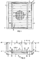
- FIG. 1 to 4 show a pressure wave protective flap 1 (hereinafter referred to as protective flap) for installation in or attachment to ducts of ventilation and / or air conditioning systems. It has, compare in particular FIG. 1, a frame 2 which is made up of two upright spars 3 arranged in mirror image to one another and two likewise mirror image to one another see horizontal bars 4 is composed. All spars 3 and 4 are preferably made of sheet metal by folding, the spars 3 having a substantially C-shaped cross section (FIG. 3) and the spars 4 having a substantially Z-shaped cross section (FIG. 2).
- a support grid 5 is installed, which is composed of vertical bars 7 and 8 and horizontal bars 9. All bars 7, 8 and 9 consist of relatively thin sheet metal, for example in the thickness between 1 and 3 mm thick.
- the depth of the support grid is defined by the width b of the horizontal bars 9, it corresponds to the depth of the frame section 10 determined by the closer legs of the horizontal bars 4. It is a multiple, for example six times larger than the respective width 11 of the vertical Lattice bars 7 and 8.
- the pitch 12 between adjacent, horizontal bars 9 is selected in the exemplary embodiment equal to the pitch 13 between adjacent, vertical bars 7, while the pitch 14 between adjacent, vertical bars 8 (rear lattice plane eO-eO) is three times that The spacing is 12 or 13.
- the outer longitudinal edge of the vertical bars 7 and the one longitudinal edge of the horizontal bars 9 lie on or in a common plane e-e, which in turn is arranged flush with the Z-webs 4.0 of the horizontal bars 4 of the frame 2, see FIG. 2.
- the outer longitudinal edge of the vertical lattice bars 8 and the other longitudinal edge of the horizontal lattice bars 9 are also arranged in a common flow-cross plane e0-e0, which is flush with a frame end edge, compare FIGS. 2, 3.
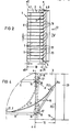
- Each individual lamella 15 is formed by a flat or slightly curved (curved) sheet metal strip, the width of which is dimensioned to be greater by the material thickness of a horizontal lattice bar 9 than the pitch 12 between two horizontal lattice bars 9, so that in the closed position an overlap or Overlap with the neighboring horizontal lattice bar and the lower end of the neighboring lamella is ensured.
- All the slats 15 can be pivoted about horizontal axes parallel to one another, and in each case can be tilted about their lower longitudinal edge 16, between the vertical bars 3 of the frame 2.
- the sheet metal strips forming the lamellae can each be provided at their ends with a molded nose 17 or an attached pin, which protrude into circular holes 18 which are located in the vertical bars 3 of the frame 2 at the level of the horizontal bars 9 of the support grid 5 are located.
- the material thickness of the sheet metal strips forming the lamella 15 is preferably chosen between 0.5 and 1.0 mm.
- each lamella 15 engage near its free longitudinal edge a plurality of leaf springs 21, in such a way that they are effective in the plane of the stop webs 20. As indicated in 21.1, they are connected to these by rivets or points in the area of the free longitudinal edge of the slats. With their other end, these leaf springs 21 lie freely on the top of the horizontal lattice bar 9 adjacent to the respective tilt axis 16, 17, compare in particular FIGS. 2 and 4.
- Each leaf spring 21 can be made of spring steel strip, which is preferably of a thickness of has about 0.2 mm. The width of the spring steel strip, on the other hand, is chosen differently depending on the desired spring force. Widths between 20 and 30 mm have proven successful.
- All components of the protective flap 1 are expediently made of non-rusting material, e.g. Light metal, stainless steel or titanium alloys. This material recommendation applies to the slats 15 and also to the support grid including its frame construction.
- the fins 15 are pressed against the force of the leaf springs 21 into the position shown in dashed lines in FIG. 4 on their seats and thus the protective flap 1 is closed. With pressure waves of the order of 1.25 bar, closing times of the protective flap for this process of less than 6 ms could be achieved.
- the support grid 5 absorbs the compressive forces acting on them, the relatively small distances between the individual bars 7 and 9 contributing to the fact that the slats 15 withstand the local pressure load despite their small thickness and light weight.
- horizontal grating bars 9 form impact diffusers which considerably reduce the flow resistance of the protective flap 1.
- the horizontal lattice bars 9 have an extension b in the flow direction 22 (cf. FIG. 3) which is a multiple of the width a (see FIG. 4) of the narrowest flow cross section between adjacent fins 15, this narrowest flow cross section being the same corresponds to the smallest distance between adjacent slats 15 in their open position.
- the support lattice depth b of the horizontal lattice bars 9 must therefore be at least the same, but preferably greater, and in fact several times greater than the vertical support lattice depth Bars 7, 8 is.
- the engagement of the lattice bars is expediently carried out alternately by means of slots and webs, in order to build up a stable supporting lattice field.
- the arrangement can be such that the depth of the slots 9.1 and 9.2 is only half the bar width of the vertical bars 7 and 8 and the latter are also provided with a slit at half their width, so that according to the so-called egg crate principle, a mutual , positive engagement between slots of one group of bars and webs of the other group of bars.
- the grille bars are arranged upright in the flow direction 22.
- the pitch 12 of the support grid 5 is, as mentioned, matched to the strip width of the slats; in the case of smaller protective flaps or support grids, a support grid consisting only of, for example, horizontal or only one-way grating bars would be sufficient to support the slats, in each case in the region of their two longitudinal edges.
- a support grid consisting only of, for example, horizontal or only one-way grating bars would be sufficient to support the slats, in each case in the region of their two longitudinal edges.
- the spacing 13 of the vertical bars 7 from one another is chosen to become smaller as the pressure load on the slats 15 increases. In the example shown, it is in particular approximately equal to the pitch 12 between the horizontal bars 9, so that one can speak of a square support grid. On the other hand, if the separation distance 13 were to decrease even further with a greater pressure load, there would be a rectangular support grid with an increased number of support points formed by the vertical rods 7 and distributed over the lamella length.
- this is provided with a coating after the assembly (not shown in detail).
- This coating can e.g. applied by spraying or dipping, it can be made of a suitable plastic or a coating metal, e.g. Zinc, or a paint.
- the leaf spring 21 is fastened at one end to the slat at 21.1 and is slidably guided at the other end on the facing flat side of the adjacent, horizontal lamella rod 9 running parallel to the slats, that is to say the force application point 21.1 is the attachment point, force application point 21.2 is the spring sliding seat.
- a relatively low bending stress of the spring occurs during the closing process, which has a life-extending effect, and in the case of aluminum slats 15, sliding or sliding of the spring steel on the slat is avoided.
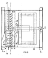
- FIGS. 5 and 9 An essential modification can be seen from FIGS. 5 and 9:
- the slats A15 are articulated to the support grid A5 in the region of their longitudinal sides A15u close to the swivel axis, at least in a plurality of articulation points 24 distributed over their length.
- thirteen articulation points of the type shown in FIG. 9 could also be provided for each lamella A15.
- These are designed so that the slats A15 on their long axis A15u near the pivot axis are angled, as shown, the angled portion A15.1 (short leg) being about 1/10 to 1/5 the length of the longer slat leg A15.1 .
- the lamellae A15 engage in groove-shaped recesses 25 of lattice bars running across the lamellae and, in the example shown, also vertical lattice bars A7 such that they are pivotably guided in the manner of cutting edges.
- the closed position of the slats ⁇ 15 is also indicated in broken lines in FIG. 9: In the closed position A15 ', the bend A15.1 lies on the underside of the horizontal lattice bars A9, and the longer slat leg A15.1 overlaps with the Neighboring slats arranged above it on the line h1 and with the edge of the associated horizontal lattice bar on the line h2.
- the pivot bearing is supplemented by the leaf spring arrangement A21, which corresponds to that according to FIG. 4, and by the stop web A20, which in this embodiment has stop surfaces A20.1, which are formed by sawtooth-shaped recesses on the stop web A20 and their inclination to the desired Tilt angle ⁇ (see FIG. 4) corresponds to the slats, so that in the open position shown there is a flat contact and support of the slats A15.
- two stop webs A20 are also provided here, which are firmly connected to the lattice frame A2 and, with their narrow sides pointing in the flow direction A22 and in the pressure surge direction, are arranged in front of the lamella field (see also FIGS. 5, 6 and 8th).
- These stop bars are designed as angle strips, which are screwed at their upper and lower ends (see FIGS. 6 and 8) to mounting brackets 26, the latter being welded to the horizontal frame bars A4.
- the vertical stop bars A20 also serve to support a test device, designated as a whole as 27, for the closing function of the slats A15. Specifically, the test device 27 (cf. FIGS.
- the stop bars A20 serve, as can be seen, for the rotatable mounting of the shaft 27.2 of the knife shaped actuator 27.1; for this purpose they are provided with corresponding bearing bushes 27.3 or bushings 27.4. Another bearing bush with shaft bushing is shown on the wall 23.3 of the channel section 23 at 27.5.
- This bearing bush is welded to the duct wall.
- the shaft 27.2 leads through them to the outside.
- the outwardly projecting end of the shaft 27.2 is provided with an actuating lever 27.6, which is fixed in its illustrated central zero position, for example by a bolt 29, by means of a bracket 28 which is approximately Z-shaped in cross section and which is welded onto the outside of the channel flange 23.1. which is inserted through corresponding holes in the bracket 28 and the free end of the actuating lever 27.6.
- the frame construction of the second embodiment is somewhat different from that of the first example, for which reference is made in particular to FIGS. 5, 8 and 10.
- angled holding brackets 30 are welded to one leg 30.1, so that the other leg 30.2 of the holding brackets 30 projecting into the interior of the channel forms a fastening plane for the supporting grid construction (plane e0-e0).
- the vertical spars A3 which have a U-profile with an unequal leg length, are screwed to their base on this fastening plane of the holding iron 30 (FIG. 10).
- the lattice frame A2 is completed by the horizontal bars A4, which are connected to the upper and lower ends of the vertical bars A3 in a manner that cannot be seen in more detail, for example, are screwed or welded.
- the side flanks of the vertical spars A3, namely their longer U-legs, thus form fastening surfaces for the horizontal lattice bars A9, which are bent at the ends A9.1 with the Side flanks of the vertical bars A3 are each screwed (Fig. 10).
- the design of the vertical spars A3 as U-profile bars allows the formation of lateral housing pockets or spaces 31 which - as explained further below with reference to FIG. 14 - can advantageously serve to accommodate damping devices for the slats A15.
- the long U-leg of the vertical bars A3 is shortened somewhat so that the damping device can engage laterally on the end faces of the slats A15.
- the mode of operation of the test device 27 is such that when the actuating lever 27.6 is pivoted upward, the knife-shaped actuator 27.1 comes into engagement with the upper half of the lamella field and presses these lamellae into their closed position. Since the lower, initially still open slat field half must allow twice the flow rate to flow, the flow speed doubles and the dynamic pressure increases, so that the lower slat field half now goes into the closed position if it functions properly. Accordingly, the functionality of the upper half of the slats can be checked by pivoting the knife-shaped actuator 27 into the lower closed position, so that the test device 27 is a simple, reliably working device with which the smooth movement of the slats can be easily checked. This test is of course only short-term and therefore practically does not interfere with operation - assuming that several protective flaps connected in parallel are used, as usual.
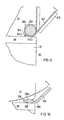
- FIG. 11 shows a third exemplary embodiment of the lamella mounting, in which the lamellae B15 Leaf springs B21 are structurally combined and the lamellar leaf spring unit B15 - B21 is fastened to the support grid A5 with the end of a free leaf spring piece B21.1 projecting beyond the lamella surface, forming a spring joint B24.
- a thickened or bent leaf spring end B21.2 is caught in groove-shaped recesses B25 of lattice bars A7 running across lamella by cross pins B32 inserted into the groove-shaped recesses, with partial wrap of the latter, the transverse pin B32 forming the hinge axis around which the lamella-leaf spring unit B15 - B21 is pivotable.
- the lamellae C15 are articulated with articulated eyes C33 formed by flanges on articulated pins C32 that are fixed to the lattice and parallel to the lamellae.
- the mounting of the leaf spring C21 is alternating from that according to Fig.4 and Fig.9 so that the leaf spring end C21.1 can slide on the slats C15 (sliding engagement) and the other leaf spring end C21.2 in slots C34.1 one additional, firmly connected to the support grid vertical bar C34.
- the lamellae C15 are further provided on their free longitudinal sides C15 o with obtuse-angled bends C15.3, with which they rest in the closed position (shown in FIG. 12 above) on the articulated eyes C33 of the neighboring lamella.
- These bends C15.3 could be omitted if the hinge pins C32 were to run parallel to the lamellae and axles through groove-shaped recesses, as in the example according to FIG. 11.
- FIG. 13 A fifth exemplary embodiment of a suitable lamella mounting is shown in detail in FIG. 13 provides, in which the slats D15 are made of tough-elastic plastic and the slat joint is formed by a flexible slat skin D35 with a smaller cross-section, which connects the actual slat D15 with a fastening part D36, which is also fastened in a groove-shaped recess D25 on the supporting grid.
- D9 are the horizontal bars again, D7 the vertical bars.
- the fastening can be facilitated by means of cams D36.1 on the fastening part D36 and associated beads on the wall of the groove-shaped recess D25 in the sense of an easy to produce snap connection.
- the protective flap according to the invention responds relatively quickly, measures to prevent fluttering are particularly important in the event of a response.
- An important measure is that the slats 15, A15, etc. are spring-loaded individually or in groups with different characteristics, so that they come out of phase with each other in response to the response to the closed position.
- this measure can be implemented relatively simply by coupling leaf springs 21, A21, etc. of different spring characteristics as return springs to the slats, the different spring stiffnesses of which are produced as a result can that the leaf spring width, ie the expansion of the leaf springs in the longitudinal direction of the slats, is varied.
- FIG. 8 This is not shown in the drawing, but is obtained in a simple manner when looking at, for example, FIG. 8 if one imagines that the two leaf springs A21 shown there widened for the adjacent lamella or in their number of two Eg three are enlarged.
- the leaf spring arrangement and dimensioning shown in FIG. 8 can then be used for the next slat, or a third leaf spring stiffness could be selected so that, and this is the point of such a measure, not all slats close at the same time, but of slats to lamella or from lamella group to lamella group with phase shift.
- the pressure recoil which would otherwise occur in the event of a sudden abrupt closing and which would cause the fluttering cannot develop, or at least not at a critical level.
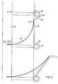
- FIG. 14 A further advantageous and effective measure which can be used in combination with the variation of the spring stiffness explained above is shown in FIG. 14.
- this involves the generation of spring forces P F of a defined size acting on the side flanks of the slats A15 in order to generate friction damping on the slats A15 during their closing movement.
- approximately vertical U-shaped spring guide rails A36 are arranged on the vertical frame parts A3 of the support grid A5 adjacent to the lamella side flanks A15.4 and with their U legs A36.1, A36.2 facing them.
- the spring guide rail A36 also has a mounting leg A36.3, with which it is connected to the vertical frame part, in particular is screwed tight.
- a cross-sectionally approximately U-shaped friction b -rail A37 is mounted such that it can move in the longitudinal direction of the slats, and its flat bottom A37.0 faces the slat side flanks A15.4. It is also with its U-legs A37.1 and A37.2 on the corresponding U-legs A36.1, A36.2 of the spring guide rail A36 slidably guided.
- A37 spring elements A38 are arranged, by means of which the friction rail A37 can be pressed over its entire length against the side flanks A15.4 of the slats A15 with a defined pressing force.
- helical compression springs are used as spring elements, which, evenly distributed over the length of the spring guide rail A36, are mounted in corresponding receiving chambers A39.
- the receiving chambers A39 can be formed by cylindrical or pot-shaped parts which are connected to the bottom of the spring guide rail A36, for example by spot welding. It is easy to control the frictional forces by the number and spring stiffness of the spring elements A38. If only the left end of a support grid with lamella is shown in FIG. 14, corresponding to the representation in FIG. 10, it is understood that the damping arrangement according to FIG.
- the measures of varying the spring stiffness for the lamellae individually or in groups and the measures described in FIG. 14 for damping the movement of the lamellae, either individually or in combination, are entirely sufficient, a flutter to prevent the slats.
- a braking device which acts as an additional device for both the first and the second off leadership example is applicable. It is a braking device with at least one brake crossbar A40, which is mounted on the frame structure A2, namely by means of a carrying crossbar A3.0, in the closed and open position of the disks A15, and is moved back and forth according to arrow A 41, which is in its Rest position R (shown) touches the free longitudinal edges of the plates A15 and in their braking position - see the arcs A42 around the pivot bearing points A43 - lies flat on the closed plates.
- the brake crossmember A40 has such an effective area exposed to the pressure surge A22 that it comes into the closed position together with the plates A15, means being provided for the brake crossmember A40 in its braking position for at least a period of 0.5 to several seconds to leave.
- the brake crossmember A40 is advantageously articulated via a dead center gear A44 to the frame structure A2 or to the support crossbar A3.0 connected to it, and assumes an over-dead center position when the brake is engaged.
- the brake crossbar A40 is articulated in the example shown by means of parallelogram linkage A45 to the support crossbar A3.0 arranged parallel to it.
- the articulation points of the parallelogram linkage A45 with respect to the crossbeam are designated with A43 and those with regard to the brake crossbar with A43.1.
- Dead center springs designed as coil tension springs A47 (only shown in the upper part of FIG. 15), are attached to the fixed points A46 and engage with their other end at the articulation points A43.1 between the brake crossbar A40 and the parallelogram lever A45.
- the brake crossmember A40 In the closed position, the brake crossmember A40 assumes a position which is indicated by the dashed circular arcs, the articulation points indicated at A43.1 'and the brake crossmember contour shown in dashed lines at A40' is defined.
- timing element A48 which triggers when the brake crossbar A40 responds and, after the predetermined delay time has elapsed, triggers an energy accumulator charged due to the closing movement of the brake crossbar to return the brake crossbar to its rest position.
- a timer A48 which can be a mechanically or mechanically-hydraulically operating timer, in the manner of the self-timer in cameras.
- the brake crossmember A40 moves towards the plunger A48.1 of the timing element A48 during its closing movement according to arrow A49 and presses this plunger against the force of a force storage spring into the housing of the timing element A48, as a result of which a housing is arranged in this housing and through it Tensioning process triggered delay gear starts to work and after the desired delay time pushes the plunger A48.1 out of the housing again using the force of the energy storage spring, so that the brake crossbar A40 moves against the force of the dead center springs A47 beyond the dead center and thus automatically into its rest position R can be brought.
- the stop bars A20 could be used to attach this braking device.
- FIG. 16 to 18 show some support grid configurations, namely FIG. 16 a support grid E5, which has only horizontal grid bars E9 within the frame E2; Fig. 17 a support grid F5, wel horizontal grids F9 and, in contrast, oblique grids F7 running within the frame F2 to form diamond-shaped grid fields, and finally FIG. 18 shows a supporting grid G5 within a frame G2 with rectangular or square-concentric grids G9 of a first set of bars and crossing this first set of bars , radial bars G7 of a second group of bars.
- the invention is therefore not limited to the right-angled cross-lattice configuration according to the first and second exemplary embodiments and also not to horizontal and vertical lattice bars, although this embodiment is the preferred one for practical reasons.
- the protective flap against pressure surges, the direction of which coincides with the direction of the gaseous media flowing through the opened protective flap from the slats to the supporting grid during normal operation (flow direction 22).
- the protective flap can also be used as a non-return flap, whereby the gaseous media flowing in normal direction through the open flap in other directions, namely from the support grid to the slats, hold the slats against their stops and the slats into the reversing flow in the event of a fault Closed position are movable against their support grid seats. Since the protective flap according to the invention, as shown in particular in FIG.
- Another embodiment essential to the invention is characterized in that on both sides of the support grid 7, 9 or A7, A9, doh. further slats of the protective flap can also be arranged on the support grille side facing away from the slats 15, A15, a pressure wave protection function then being provided in both directions, or one slat field then acting as a pressure wave protection flap and the other as a non-return flap and vice versa.
- This embodiment is not shown in the drawing, but is readily obtained when looking at FIGS. 2 or 5, 9, if the lamella fields 15 and A15 are mirrored about a flow-normal support grid symmetry plane or point symmetrically on the other support grid - End face shifted thinks.
- the double pressure wave protective flap by connecting two supporting grids in series in the flow direction and assigning a lamella field to each supporting grid on its outside or on its side facing away from the neighboring supporting grid.
- Preference is given, however, to the above-mentioned embodiment of a double pressure-wave protective flap with only one supporting grille and one lamella field on each of the two supporting grille sides pointing in the direction of flow or opposite thereto because of the more compact construction and material savings.
Landscapes
- Engineering & Computer Science (AREA)
- General Engineering & Computer Science (AREA)
- Chemical & Material Sciences (AREA)
- Fluid Mechanics (AREA)
- Combustion & Propulsion (AREA)
- Mechanical Engineering (AREA)
- Physics & Mathematics (AREA)
- Air-Flow Control Members (AREA)
- Specific Sealing Or Ventilating Devices For Doors And Windows (AREA)
- Structure Of Emergency Protection For Nuclear Reactors (AREA)
- Ventilation (AREA)
- Air Conditioning Control Device (AREA)
- Operating, Guiding And Securing Of Roll- Type Closing Members (AREA)
Applications Claiming Priority (2)
| Application Number | Priority Date | Filing Date | Title |
|---|---|---|---|
| DE8208932U | 1982-03-29 | ||
| DE19828208932U DE8208932U1 (de) | 1982-03-29 | 1982-03-29 | Druckwellen-schutzklappe fuer kanaele von lueftungs- und/oder klimaanlagen |
Publications (2)
| Publication Number | Publication Date |
|---|---|
| EP0090415A1 true EP0090415A1 (fr) | 1983-10-05 |
| EP0090415B1 EP0090415B1 (fr) | 1986-06-11 |
Family
ID=6738535
Family Applications (1)
| Application Number | Title | Priority Date | Filing Date |
|---|---|---|---|
| EP83103125A Expired EP0090415B1 (fr) | 1982-03-29 | 1983-03-29 | Volets de protection contre des ondes de surpression |
Country Status (5)
| Country | Link |
|---|---|
| US (1) | US4576088A (fr) |
| EP (1) | EP0090415B1 (fr) |
| JP (1) | JPS59500425A (fr) |
| DE (2) | DE8208932U1 (fr) |
| WO (1) | WO1983003462A1 (fr) |
Cited By (1)
| Publication number | Priority date | Publication date | Assignee | Title |
|---|---|---|---|---|
| EP2297526A4 (fr) * | 2008-05-09 | 2015-04-15 | Temet Oy | Soupape de pression |
Families Citing this family (13)
| Publication number | Priority date | Publication date | Assignee | Title |
|---|---|---|---|---|
| US5137231A (en) * | 1991-04-29 | 1992-08-11 | The Boeing Company | Decompression venting grille for aircraft |
| FR2725769A1 (fr) * | 1994-10-12 | 1996-04-19 | Abb Flakt | Regulateur de debit perfectionne, notamment pour installation de ventilation ou de climatisation |
| US6149515A (en) * | 1998-10-16 | 2000-11-21 | Tomkins Industries, Inc. | Combination moisture elimination louver and air flow sensor and method |
| US6427310B1 (en) * | 2000-02-15 | 2002-08-06 | Eastman Kodak Company | Method for fabricating a print engine chassis for supporting an imaging drum and printhead translation assembly |
| US7624732B2 (en) * | 2005-10-06 | 2009-12-01 | The Boeing Company | Method and apparatus for extending flight crew's time of useful consciousness after decompression |
| DE102007061433B4 (de) * | 2007-12-20 | 2012-10-25 | Airbus Operations Gmbh | Verbesserte Dekompressionseinrichtung mit einem einstellbaren Auslösedruck |
| DE102008040462B4 (de) | 2008-07-16 | 2013-09-12 | Sommer Metallbau-Stahlbau Gmbh & Co. Kg | Druckstoßklappe |
| GB2526507B (en) * | 2013-01-07 | 2022-05-25 | Scott Ross Alexander | Emergency roofing and barrier system |
| NZ709141A (en) | 2013-03-14 | 2019-08-30 | Hunter Douglas | Shutter panel for an architectural opening |
| CN103277860A (zh) * | 2013-06-14 | 2013-09-04 | 苏州原点工业设计有限公司 | 一种设有挂钩的冷风机 |
| EP2980346A1 (fr) | 2014-07-31 | 2016-02-03 | Hunter Douglas Industries B.V. | Ensemble obturateur |
| IL247805B (en) | 2016-09-13 | 2022-05-01 | Beth El Zikhron Yaaqov Ind Ltd | Wing-based explosion valve in an aeronautical structure |
| CA3087168A1 (fr) | 2019-07-26 | 2021-01-26 | Hunter Douglas Inc. | Panneau-guichet dote d`un ensemble de fermeture automatique de persienne et elements d`amortissement connexes |
Citations (7)
| Publication number | Priority date | Publication date | Assignee | Title |
|---|---|---|---|---|
| GB569013A (en) * | 1943-05-13 | 1945-05-01 | Leonard Gordon Davies | Improvements relating to ventilators and to the control of flow of fluids |
| DE1227345B (de) * | 1960-11-08 | 1966-10-20 | Ewers & Miesner Hartgusswerk | Selbsttaetige Verschlussvorrichtung fuer Be- und Entlueftungsleitungen von Schutzraeumen |
| US3301168A (en) * | 1963-04-18 | 1967-01-31 | Luwa Ag | Quick closure mechanism for the air passage openings of shelters and the like |
| CH473957A (de) * | 1967-05-03 | 1969-06-15 | Catrinus De Jonge Martinus | Rost |
| DE7133893U (de) * | 1971-09-06 | 1972-11-23 | F Driescher Spezialfab Fuer Elektrizitaetswerksbedarf | Lüftungsfenster für Transformator-Stationen |
| US4167898A (en) * | 1976-01-06 | 1979-09-18 | Barcant Kevin C | Illumination and ventilation system for buildings |
| DE2839998A1 (de) * | 1978-09-14 | 1980-04-03 | Betonbau Gmbh | Luefterelement zum einbau in die aussenwand eines gebaeudes |
Family Cites Families (2)
| Publication number | Priority date | Publication date | Assignee | Title |
|---|---|---|---|---|
| US2965014A (en) * | 1958-09-02 | 1960-12-20 | Lowery Charley | Vent closing louver apparatus |
| ZW3586A1 (en) * | 1985-03-12 | 1986-06-11 | Bayer Ag | Macroemulsions |
-
1982
- 1982-03-29 DE DE19828208932U patent/DE8208932U1/de not_active Expired
-
1983
- 1983-03-29 DE DE8383103125T patent/DE3364041D1/de not_active Expired
- 1983-03-29 EP EP83103125A patent/EP0090415B1/fr not_active Expired
- 1983-03-29 WO PCT/DE1983/000061 patent/WO1983003462A1/fr not_active Ceased
- 1983-03-29 JP JP58501179A patent/JPS59500425A/ja active Granted
- 1983-03-29 US US06/558,032 patent/US4576088A/en not_active Expired - Fee Related
Patent Citations (7)
| Publication number | Priority date | Publication date | Assignee | Title |
|---|---|---|---|---|
| GB569013A (en) * | 1943-05-13 | 1945-05-01 | Leonard Gordon Davies | Improvements relating to ventilators and to the control of flow of fluids |
| DE1227345B (de) * | 1960-11-08 | 1966-10-20 | Ewers & Miesner Hartgusswerk | Selbsttaetige Verschlussvorrichtung fuer Be- und Entlueftungsleitungen von Schutzraeumen |
| US3301168A (en) * | 1963-04-18 | 1967-01-31 | Luwa Ag | Quick closure mechanism for the air passage openings of shelters and the like |
| CH473957A (de) * | 1967-05-03 | 1969-06-15 | Catrinus De Jonge Martinus | Rost |
| DE7133893U (de) * | 1971-09-06 | 1972-11-23 | F Driescher Spezialfab Fuer Elektrizitaetswerksbedarf | Lüftungsfenster für Transformator-Stationen |
| US4167898A (en) * | 1976-01-06 | 1979-09-18 | Barcant Kevin C | Illumination and ventilation system for buildings |
| DE2839998A1 (de) * | 1978-09-14 | 1980-04-03 | Betonbau Gmbh | Luefterelement zum einbau in die aussenwand eines gebaeudes |
Cited By (1)
| Publication number | Priority date | Publication date | Assignee | Title |
|---|---|---|---|---|
| EP2297526A4 (fr) * | 2008-05-09 | 2015-04-15 | Temet Oy | Soupape de pression |
Also Published As
| Publication number | Publication date |
|---|---|
| DE8208932U1 (de) | 1982-08-12 |
| JPS59500425A (ja) | 1984-03-15 |
| JPS6238618B2 (fr) | 1987-08-19 |
| DE3364041D1 (en) | 1986-07-17 |
| WO1983003462A1 (fr) | 1983-10-13 |
| US4576088A (en) | 1986-03-18 |
| EP0090415B1 (fr) | 1986-06-11 |
Similar Documents
| Publication | Publication Date | Title |
|---|---|---|
| EP0090415B1 (fr) | Volets de protection contre des ondes de surpression | |
| EP2847410B1 (fr) | Système de porte relevable ainsi que dispositif d'étanchéité de linteau de porte | |
| DE3438709C1 (de) | Kuehlerjalousie | |
| EP0266642A1 (fr) | Pare-chocs en matériau composite | |
| EP2602144B1 (fr) | Extrémité frontale d'un véhicule | |
| DE2138966C3 (de) | Vorgefertigte Flanschverbindung | |
| EP0157198B1 (fr) | Porte roulante avec vantail de porte flexible | |
| DE4340115C2 (de) | Jalousie zur Regulierung eines Gasstroms | |
| DE3311455A1 (de) | Druckwellen-schutzklappe | |
| DE2727608A1 (de) | Tuerfeststeller fuer fahrzeugtueren | |
| EP0838426A2 (fr) | Vantail de porte, notamment pour ascenseurs | |
| DE102008040462B4 (de) | Druckstoßklappe | |
| DE102017116545A1 (de) | Ablageeinrichtung | |
| EP0616179B1 (fr) | Dispositif d'obturation d'un passage d'air | |
| DE19641053B4 (de) | Speichereinheit zur Aufnahme einer rolladenartigen Abdeckung einer Montagegrube sowie rolladenartige Abdeckung | |
| CH654639A5 (de) | Explosionsschutzventil an luftdurchlaessen, insbesondere fuer schutzraeume. | |
| EP1302220B1 (fr) | Clapet, notamment clapet coupe-feu | |
| DE60114689T2 (de) | Kabelkanal und dafür geeignete Klemmschelle | |
| DE2534297C2 (de) | Feuerschutzklappe | |
| DE202010005197U1 (de) | Bodentürdichtung | |
| DE202009012128U1 (de) | Jalousieklappensystem | |
| DE2520354C3 (de) | Elektrisch beheizter Brotröster | |
| EP0049434B1 (fr) | Couvercle pour faux-plafonds à résilles | |
| DE1255501B (de) | Verschlussventil fuer Luftleitungen von Schutzbauten | |
| DE7705685U1 (de) | Absperrvorrichtung, insbesondere druckentlastungsjalousieklappe |
Legal Events
| Date | Code | Title | Description |
|---|---|---|---|
| PUAI | Public reference made under article 153(3) epc to a published international application that has entered the european phase |
Free format text: ORIGINAL CODE: 0009012 |
|
| AK | Designated contracting states |
Designated state(s): CH DE FR GB LI NL SE |
|
| 17P | Request for examination filed |
Effective date: 19831213 |
|
| GRAA | (expected) grant |
Free format text: ORIGINAL CODE: 0009210 |
|
| AK | Designated contracting states |
Kind code of ref document: B1 Designated state(s): CH DE FR GB LI NL SE |
|
| REF | Corresponds to: |
Ref document number: 3364041 Country of ref document: DE Date of ref document: 19860717 |
|
| ET | Fr: translation filed | ||
| PLBE | No opposition filed within time limit |
Free format text: ORIGINAL CODE: 0009261 |
|
| STAA | Information on the status of an ep patent application or granted ep patent |
Free format text: STATUS: NO OPPOSITION FILED WITHIN TIME LIMIT |
|
| 26N | No opposition filed | ||
| PGFP | Annual fee paid to national office [announced via postgrant information from national office to epo] |
Ref country code: GB Payment date: 19920228 Year of fee payment: 10 |
|
| PGFP | Annual fee paid to national office [announced via postgrant information from national office to epo] |
Ref country code: FR Payment date: 19920323 Year of fee payment: 10 |
|
| PGFP | Annual fee paid to national office [announced via postgrant information from national office to epo] |
Ref country code: SE Payment date: 19920324 Year of fee payment: 10 |
|
| PGFP | Annual fee paid to national office [announced via postgrant information from national office to epo] |
Ref country code: NL Payment date: 19920331 Year of fee payment: 10 |
|
| PGFP | Annual fee paid to national office [announced via postgrant information from national office to epo] |
Ref country code: DE Payment date: 19920521 Year of fee payment: 10 |
|
| PGFP | Annual fee paid to national office [announced via postgrant information from national office to epo] |
Ref country code: CH Payment date: 19920622 Year of fee payment: 10 |
|
| PG25 | Lapsed in a contracting state [announced via postgrant information from national office to epo] |
Ref country code: GB Effective date: 19930329 |
|
| PG25 | Lapsed in a contracting state [announced via postgrant information from national office to epo] |
Ref country code: SE Effective date: 19930330 |
|
| PG25 | Lapsed in a contracting state [announced via postgrant information from national office to epo] |
Ref country code: LI Effective date: 19930331 Ref country code: CH Effective date: 19930331 |
|
| PG25 | Lapsed in a contracting state [announced via postgrant information from national office to epo] |
Ref country code: NL Effective date: 19931001 |
|
| NLV4 | Nl: lapsed or anulled due to non-payment of the annual fee | ||
| GBPC | Gb: european patent ceased through non-payment of renewal fee |
Effective date: 19930329 |
|
| PG25 | Lapsed in a contracting state [announced via postgrant information from national office to epo] |
Ref country code: FR Effective date: 19931130 |
|
| REG | Reference to a national code |
Ref country code: CH Ref legal event code: PL |
|
| PG25 | Lapsed in a contracting state [announced via postgrant information from national office to epo] |
Ref country code: DE Effective date: 19931201 |
|
| REG | Reference to a national code |
Ref country code: FR Ref legal event code: ST |
|
| EUG | Se: european patent has lapsed |
Ref document number: 83103125.7 Effective date: 19931008 |