EP0090614B1 - Apparat zur Halterung einer Speicherkassette - Google Patents
Apparat zur Halterung einer Speicherkassette Download PDFInfo
- Publication number
- EP0090614B1 EP0090614B1 EP83301680A EP83301680A EP0090614B1 EP 0090614 B1 EP0090614 B1 EP 0090614B1 EP 83301680 A EP83301680 A EP 83301680A EP 83301680 A EP83301680 A EP 83301680A EP 0090614 B1 EP0090614 B1 EP 0090614B1
- Authority
- EP
- European Patent Office
- Prior art keywords
- memory cassette
- lever
- cassette
- data
- memory
- Prior art date
- Legal status (The legal status is an assumption and is not a legal conclusion. Google has not performed a legal analysis and makes no representation as to the accuracy of the status listed.)
- Expired
Links
- 230000007246 mechanism Effects 0.000 claims description 15
- 230000004044 response Effects 0.000 claims 1
- 238000010586 diagram Methods 0.000 description 2
- 238000010276 construction Methods 0.000 description 1
- 230000000694 effects Effects 0.000 description 1
- 238000000605 extraction Methods 0.000 description 1
- 238000003754 machining Methods 0.000 description 1
- 239000002184 metal Substances 0.000 description 1
- 239000004065 semiconductor Substances 0.000 description 1
Images


Classifications
-
- G—PHYSICS
- G11—INFORMATION STORAGE
- G11C—STATIC STORES
- G11C19/00—Digital stores in which the information is moved stepwise, e.g. shift registers
- G11C19/02—Digital stores in which the information is moved stepwise, e.g. shift registers using magnetic elements
- G11C19/08—Digital stores in which the information is moved stepwise, e.g. shift registers using magnetic elements using thin films in plane structure
- G11C19/085—Generating magnetic fields therefor, e.g. uniform magnetic field for magnetic domain stabilisation
-
- G—PHYSICS
- G11—INFORMATION STORAGE
- G11B—INFORMATION STORAGE BASED ON RELATIVE MOVEMENT BETWEEN RECORD CARRIER AND TRANSDUCER
- G11B15/00—Driving, starting or stopping record carriers of filamentary or web form; Driving both such record carriers and heads; Guiding such record carriers or containers therefor; Control thereof; Control of operating function
- G11B15/02—Control of operating function, e.g. switching from recording to reproducing
- G11B15/04—Preventing, inhibiting, or warning against accidental erasing or double recording
-
- G—PHYSICS
- G11—INFORMATION STORAGE
- G11B—INFORMATION STORAGE BASED ON RELATIVE MOVEMENT BETWEEN RECORD CARRIER AND TRANSDUCER
- G11B15/00—Driving, starting or stopping record carriers of filamentary or web form; Driving both such record carriers and heads; Guiding such record carriers or containers therefor; Control thereof; Control of operating function
- G11B15/675—Guiding containers, e.g. loading, ejecting cassettes
-
- G—PHYSICS
- G11—INFORMATION STORAGE
- G11C—STATIC STORES
- G11C5/00—Details of stores covered by group G11C11/00
- G11C5/02—Disposition of storage elements, e.g. in the form of a matrix array
- G11C5/025—Geometric lay-out considerations of storage- and peripheral-blocks in a semiconductor storage device
Definitions
- This invention relates to a memory cassette holding apparatus.
- a memory cassette such as a magnetic tape cassette, bubble memory cassette or semiconductor memory cassette. This is accomplished by loading the memory cassette in a numerical control device or NC data creation device, writing the NC data stored in the internal memory of the numerical control device, or created by the NC data creation device, into the memory cassette, and then subsequently reading the NC data out of the memory cassette to execute numerical control based on the NC data.
- an apparatus for holding a memory cassette so that data may be written into and/or read from the memory cassette comprising:
- An embodiment of the present invention may provide a memory cassette holding apparatus so adapted that the memory cassette will not be ejected during the writing and/or reading of data.
- An embodiment of the invention may provide that the data can be written and/or read correctly, and that already stored data will not be mutilated, even if an eject button is accidentally pressed when a read and/or write operation is in progress.
- a cassette holder 12 is adapted to hold an end portion 11 a of a memory cassette 11.
- a substantially L-shaped eject lever 13 constituting part of an ejecting mechanism and supported for rotation about a pivot shaft 14, has the ejector end thereof disposed in a gap formed between the memory cassette 11 and the cassette holder 12.
- An eject button 15 is so disposed as to abut against the other or right end of the eject lever 13 from the side thereof. The arrangement is such that when the eject lever 13 is rotated clockwise in Fig. 1 about the pivot shaft 14 by pressing the eject button 15, the memory cassette 11 is ejected in the direction of the arrow A.
- a data read/write controller 16 is provided for producing a signal WR when NC data stored in a memory 17 are being written into the memory cassette 11, and a signal RD when the NC data are being read out of the memory cassette.
- the signals WR, RD will be referred to as write mode and read mode signals, respectively.
- a drive circuit 18 responds by causing a locking mechanism 19 to lock the eject lever 13 against rotation even if the eject button 15 is pressed. The lever 13 will remain locked until the signal WR or WD vanishes.
- the locking mechanism 19 may comprise an ordinary electromagnet and an armature (neither of which are shown in Fig.
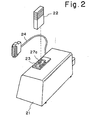
- FIG. 2 shows an adapter 21 which uses a memory cassette holding apparatus of the invention.
- the adapter 21 has a cassette inlet 23 in which a memory cassette, such as a bubble memory cassette 22, is inserted so that NC data or an NC program stored in the cassette may be read from the cassette and transferred to a numerical control device (not shown) via a connecting cable 24, or so that NC data or an NC program transferred from the numerical control device via the cable 24 may be written into the bubble memory cassete 22.
- Projecting from a slot in the adapter 21 is the distal end 27a of a lever 27 described below.
- a button or cap, not shown, is adapted to fit on the lever end 27a to facilitate the operation of the lever.
- Fig. 3 is a front view illustrating the details of a memory cassette holding apparatus embodying the present invention.
- a holding plate 26 made of metal is provided for supporting the holding apparatus in its entirety.
- the lever 27 mentioned above in connection with Fig. 2 is pivotally supported on the holding plate 26 by means of a pin 28 affixed to the holding plate. Fit onto the distal end 27a of the lever 27 is an eject button, not shown. Part of the lever 27 adjacent pin 28 is formed into a bifurcated locking portion 27b.
- the lever 27 also has a short extension 27c having a pin 27d implanted near the root portion thereof.
- a link 29 is provided having one end attached for rotation to the distal end of the extension 27c of lever 27.
- the other end of the link 29 is attached for rotation to a rack 30 which, by operation of the lever 27 acting through the link 29, is adapted to pull up the bubble memory cassette 22 to enable its extraction.
- the rack 30 is adapted for vertical movement along the line A-A in Fig. 3.
- the lever 27, link 29 and rack 30 comprise an ejecting mechanism.
- Numeral 31 designates a guide member penetrated by a locking rod 32 movable horizontally through the guide member so that one end of the rod 32 is engageable with the bifurcated locking portion 27b of the lever 27.
- a locking rod drive lever 33 is pivotally mounted on the holding plate 26.
- the locking rod drive lever 33 has a substantially L-shaped configuration, the end of one leg thereof being coupled to the other end of the locking rod 32, the end of the other leg thereof being coupled to an armature 35.
- the latter is so adapted as to be freely movable through the interior of a magnet coil 34 affixed to the holding plate 26. Energizing the magnet coil 34 draws the armature 35 inwardly thereof to the position shown in Fig. 3.
- the magnet coil 34 is connected to the drive circuit 18 (Fig.
- Numeral 38 designates a pin implanted in the holding plate 26.
- a tension spring 36 is stretched between the pin 38 and the pin 27d implanted in the extension 27c of the lever 27, and serves to hold the lever 27 in either a cassette load position, indicated by the solid lines in Fig. 3, or cassette eject position, which is indicated by the broken lines.
- a second tension spring 37 is stretched between the pin 38 and the end of the locking rod drive lever 33 coupled to the armature 35, and serves to constantly bias the drive lever 33 in the counter-clockwise direction.
- the locking rod 32, locking rod drive lever 33, magnet coil 34 and armature 35 constitute a locking mechanism. Note that the cassette holder, shown at 12 in Fig. 1, is deleted from Fig. 3 for the sake of simplicity.
- the bubble memory cassette 22 is shown already loaded in the cassette inlet 23 of the adapter 21 (Fig. 2), and the associated mechanisms are shown in the attitudes assumed during the writing or reading of information with respect to the bubble memory cassette.
- the magnet coil 34 is in the energized state so that the armature 35 is retracted into the coil.
- the locking rod drive lever 33 therefore is rotated in the clockwise direction against the pulling force of the tension spring 37, thereby pushing the locking rod 32 to the left in Fig. 3 to engage the end of the rod 32 with the bifurcated locking portion 27b of the lever 27. This locks the lever 27 against rotation, so that the bubble memory cassette 22 cannot be ejected.
- the magnet coil 34 is deenergized to release the armature 35 from the attractive force applied by the coil, so that the locking rod drive lever 33 is rotated in the counter-clockwise direction under the pulling force applied by the tension spring 37, thereby pulling the locking rod 32 to the right in Fig. 3 to disengage the end thereof from the locking portion 27b of the lever 27.
- the lever 27 now is capable of rotation about the pin 28.
- the operator may now rotate the lever 27 from the cassette load position to the eject position, whereby the link 29 interconnecting the tever 27 and the rack 30 is displaced from the position indicated by the solid lines to that indicated by the broken lines.
- the rack 30 will therefore be pulled upward in Fig. 3 along the line A-A, bringing the bubble memory cassette 22 to a position where it can be extracted from the adapter 21, shown in Fig. 2.
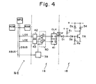
- Fig. 4 is a circuit diagram illustrating the data read/write controller 16 and drive circuit 18.
- the read/write controller 16 comprises address decoders 39,42,43 which receive input signals from a numerical control device NC, described below, a gate circuit 40 receiving the outputs of the address decoders 39, 42, 43, the gate circuit 40 having gates G1, G2 and a flip-flop circuit 41 whose set and reset terminals are connected to the outputs of the respective gates G1, G2 of the gate circuit 40.
- the drive circuit 18 comprises diodes D1, D2, D3, resistors R1, R2, a transistor TR and the magnetic coil 34 of Fig. 3.
- MPU, ROM, RAM represent a microprocessor, read-only memory and random access memory, respectively, these constituting the numerical control device NC mentioned above.
- ABUS is an address bus, and DBUS a data bus.
- the numerical control device NC is adapted to apply a signal to the address decoder 39 at the beginning and end of a read or write operation.
- the numerical control device also applies a lock start signal LOS to the address decoder 42 at the onset of a read or write operation, and a lock end signal LOE to the address decoder 43 at the end of the read or write operation.
- the flip-flop circuit 41 When information is neither being written into nor read from the bubble memory cassette 22, the flip-flop circuit 41 is in the reset state so that its Q output is low and Q output is high. Since the base of the transistor TR will be at a low potential as a result, the transistor will be non-conductive and no current will flow into the magnet coil 34. Now assume that the operator initiates a read or write operation with respect to the loaded bubble memory cassette 22.
- the numerical control device NC responds by simultaneously selecting the address decoder 39 by an address signal delivered from the address bus ABUS, whereby the address decoder 39 produces an output signal which opens both gates G1, G2 of the gate circuit 40.
- the decoder 42 produces an output signal which is passed by the open gate G1 to place the flip-flop 41 in the set state. This sends the Q output of the flip-flop 41 to the high level so that transistor TR is driven into conduction, thereby energizing the magnet coil 34. This prevents the bubble memory cassette 22 from being ejected from the adapter 21, as described above in conjunction with Fig. 3. With the bubble memory cassette 22 in the locked state, either a numerical control program stored therein is read from the cassette and transferred to the random access memory RAM, or a numerical control program stored in the RAM is transferred from the RAM to the cassette 22 for storage.
- the address decoder 39 is again selected by a signal from the address bus ABUS of the numerical control device and again responds by opening the gates G1, G2 of the gate circuit 40.
- the numerical control device now delivers a lock end signal LOE from the data bus DBUS to the input of the decoder 43, the latter responding by producing an output signal which the open gate G2 applies to the flip-flop circuit 41 to place the flip-flop in the reset state. This sends the Q output of the flip-flop to the low level, cutting off the transistor TR and de-energizing the magnet coil 34.
- the bubble memory cassette 22 is thereby released from the locked state so that the cassette can be ejected at will.
Landscapes
- Engineering & Computer Science (AREA)
- Microelectronics & Electronic Packaging (AREA)
- Automatic Tape Cassette Changers (AREA)
- Numerical Control (AREA)
Claims (4)
Applications Claiming Priority (2)
| Application Number | Priority Date | Filing Date | Title |
|---|---|---|---|
| JP1982044267U JPS58148794U (ja) | 1982-03-29 | 1982-03-29 | メモリカセツト保持装置 |
| JP44267/82 | 1982-03-29 |
Publications (2)
| Publication Number | Publication Date |
|---|---|
| EP0090614A1 EP0090614A1 (de) | 1983-10-05 |
| EP0090614B1 true EP0090614B1 (de) | 1986-07-30 |
Family
ID=12686734
Family Applications (1)
| Application Number | Title | Priority Date | Filing Date |
|---|---|---|---|
| EP83301680A Expired EP0090614B1 (de) | 1982-03-29 | 1983-03-25 | Apparat zur Halterung einer Speicherkassette |
Country Status (4)
| Country | Link |
|---|---|
| US (1) | US4544971A (de) |
| EP (1) | EP0090614B1 (de) |
| JP (1) | JPS58148794U (de) |
| DE (1) | DE3364850D1 (de) |
Families Citing this family (7)
| Publication number | Priority date | Publication date | Assignee | Title |
|---|---|---|---|---|
| JPS6235893A (ja) * | 1985-08-09 | 1987-02-16 | 第一電子工業株式会社 | 電子カ−ド着脱装置 |
| US4679747A (en) * | 1986-03-21 | 1987-07-14 | Laser Magnetic Storage International Company | Apparatus for loading and unloading the leader block of a tape cartridge |
| US4826101A (en) * | 1986-03-21 | 1989-05-02 | Smith Jay A | Apparatus for loading and unloading the leader block of a tape cartridge |
| US4828201A (en) * | 1986-03-21 | 1989-05-09 | Laser Magnetic Storage International Company | Apparatus for coupling a drive motor to a leader block loading/unloading mechanism |
| US4805045A (en) * | 1986-03-21 | 1989-02-14 | Laser Magnetic Storage International Company | Apparatus for loading and unloading a tape cartridge |
| JP3657016B2 (ja) * | 1993-05-13 | 2005-06-08 | バーグ・テクノロジー・インコーポレーテッド | コネクタ装置 |
| CN106154876A (zh) * | 2016-07-15 | 2016-11-23 | 北京光年无限科技有限公司 | 一种智能机器人及机器人操作系统 |
Family Cites Families (9)
| Publication number | Priority date | Publication date | Assignee | Title |
|---|---|---|---|---|
| DE976753C (de) * | 1951-02-17 | 1964-04-16 | Robert Bosch Elektronik Ges Mi | Elektrische Verriegelungsvorrichtung fuer Magnettongeraete |
| FR2148806A5 (de) * | 1971-08-04 | 1973-03-23 | Honeywell Bull Soc Ind | |
| JPS5146965Y2 (de) * | 1972-06-17 | 1976-11-12 | ||
| IT956806B (it) * | 1972-06-23 | 1973-10-10 | Honeywell Inf Systems | Apparecchiatura di lettura e rigi strazione magnetica su nastri ma gnetici in cassetta |
| US3875590A (en) * | 1972-09-25 | 1975-04-01 | Jazina John | Tape transport arrangement for cassettes with interlocks to prevent tape damage |
| US3973272A (en) * | 1974-10-29 | 1976-08-03 | Sycor, Inc. | Disc receiver interlock for disc recorders |
| US3957225A (en) * | 1975-05-05 | 1976-05-18 | Hewlett-Packard Company | Cartridge latching mechanism |
| DE2643997A1 (de) * | 1976-05-21 | 1978-03-30 | Siemens Ag | Vorrichtung zur ver- und entriegelung von kassetten in kassetten- magnetbandgeraeten |
| US4396963A (en) * | 1981-03-31 | 1983-08-02 | Disctron | Access door latch and interlock mechanism |
-
1982
- 1982-03-29 JP JP1982044267U patent/JPS58148794U/ja active Pending
-
1983
- 1983-03-25 DE DE8383301680T patent/DE3364850D1/de not_active Expired
- 1983-03-25 US US06/478,729 patent/US4544971A/en not_active Expired - Fee Related
- 1983-03-25 EP EP83301680A patent/EP0090614B1/de not_active Expired
Also Published As
| Publication number | Publication date |
|---|---|
| EP0090614A1 (de) | 1983-10-05 |
| US4544971A (en) | 1985-10-01 |
| DE3364850D1 (en) | 1986-09-04 |
| JPS58148794U (ja) | 1983-10-06 |
Similar Documents
| Publication | Publication Date | Title |
|---|---|---|
| US4504879A (en) | Disc drive arrangement | |
| US4539614A (en) | Flexible magnetic disk clamping an injector mechanism | |
| DE3546630C2 (de) | ||
| US4413291A (en) | Cassette tape player-recorder | |
| US4167764A (en) | Mode changing apparatus in a tape recorder | |
| US4544971A (en) | Memory cassette holding apparatus | |
| US5537376A (en) | Disk cartridge loading mechanism | |
| US4710831A (en) | Loading and unloading system for flexible disc drive apparatus | |
| US5119252A (en) | Inhibiting ejection of disc memory for selected time after power off | |
| US3902193A (en) | Cassette type tape recorder/reproducer with cassette moving carriage | |
| US4635149A (en) | Loading and ejecting mechanism in a recording and reproducing apparatus | |
| US3617650A (en) | Automatic threading mechanism using three tape loops | |
| US4816945A (en) | Improved locking and ejection mechanism for magnetic disk pack recording and reproducing apparatus | |
| US4679106A (en) | Spring loaded ejector for disc cartridge | |
| US6295180B1 (en) | Disk drive capable of preventing ejection of magnetic recording medium even upon erroneous depression of eject button during work | |
| US4393426A (en) | Tape recorder head adjusting mechanism | |
| US4651240A (en) | Disk cartridge loading and ejecting mechanism in a recording and playback apparatus | |
| EP0870301B1 (de) | Gerät zur informationsspeicherung und/oder -wiedergabe auf/von einem informationsträger | |
| KR100691637B1 (ko) | 디스크 장치 | |
| JP2567980B2 (ja) | 自動装填装置の危険防止機構 | |
| US6275662B1 (en) | Film cartridge loader for camera | |
| JPS6319958Y2 (de) | ||
| JP2743484B2 (ja) | Icカードリーダ | |
| KR930004039Y1 (ko) | 카데크의 이젝트 타이밍 제어장치 | |
| JP2539243Y2 (ja) | 磁気ディスク記録再生装置のディスク排出機構 |
Legal Events
| Date | Code | Title | Description |
|---|---|---|---|
| PUAI | Public reference made under article 153(3) epc to a published international application that has entered the european phase |
Free format text: ORIGINAL CODE: 0009012 |
|
| AK | Designated contracting states |
Designated state(s): DE FR GB |
|
| 17P | Request for examination filed |
Effective date: 19840323 |
|
| GRAA | (expected) grant |
Free format text: ORIGINAL CODE: 0009210 |
|
| AK | Designated contracting states |
Kind code of ref document: B1 Designated state(s): DE FR GB |
|
| REF | Corresponds to: |
Ref document number: 3364850 Country of ref document: DE Date of ref document: 19860904 |
|
| ET | Fr: translation filed | ||
| PLBE | No opposition filed within time limit |
Free format text: ORIGINAL CODE: 0009261 |
|
| STAA | Information on the status of an ep patent application or granted ep patent |
Free format text: STATUS: NO OPPOSITION FILED WITHIN TIME LIMIT |
|
| 26N | No opposition filed | ||
| PGFP | Annual fee paid to national office [announced via postgrant information from national office to epo] |
Ref country code: FR Payment date: 19910307 Year of fee payment: 9 |
|
| PGFP | Annual fee paid to national office [announced via postgrant information from national office to epo] |
Ref country code: GB Payment date: 19910312 Year of fee payment: 9 Ref country code: DE Payment date: 19910312 Year of fee payment: 9 |
|
| PG25 | Lapsed in a contracting state [announced via postgrant information from national office to epo] |
Ref country code: GB Effective date: 19920325 |
|
| GBPC | Gb: european patent ceased through non-payment of renewal fee | ||
| PG25 | Lapsed in a contracting state [announced via postgrant information from national office to epo] |
Ref country code: FR Effective date: 19921130 |
|
| PG25 | Lapsed in a contracting state [announced via postgrant information from national office to epo] |
Ref country code: DE Effective date: 19921201 |
|
| REG | Reference to a national code |
Ref country code: FR Ref legal event code: ST |