EP0090623A2 - Machine à découper des plaques de produits alimentaires - Google Patents
Machine à découper des plaques de produits alimentaires Download PDFInfo
- Publication number
- EP0090623A2 EP0090623A2 EP83301695A EP83301695A EP0090623A2 EP 0090623 A2 EP0090623 A2 EP 0090623A2 EP 83301695 A EP83301695 A EP 83301695A EP 83301695 A EP83301695 A EP 83301695A EP 0090623 A2 EP0090623 A2 EP 0090623A2
- Authority
- EP
- European Patent Office
- Prior art keywords
- slicing
- hydraulic
- pressure
- hydraulic fluid
- nominal
- Prior art date
- Legal status (The legal status is an assumption and is not a legal conclusion. Google has not performed a legal analysis and makes no representation as to the accuracy of the status listed.)
- Withdrawn
Links
Images
Classifications
-
- B—PERFORMING OPERATIONS; TRANSPORTING
- B26—HAND CUTTING TOOLS; CUTTING; SEVERING
- B26D—CUTTING; DETAILS COMMON TO MACHINES FOR PERFORATING, PUNCHING, CUTTING-OUT, STAMPING-OUT OR SEVERING
- B26D5/00—Arrangements for operating and controlling machines or devices for cutting, cutting-out, stamping-out, punching, perforating, or severing by means other than cutting
- B26D5/08—Means for actuating the cutting member to effect the cut
- B26D5/12—Fluid-pressure means
-
- B—PERFORMING OPERATIONS; TRANSPORTING
- B26—HAND CUTTING TOOLS; CUTTING; SEVERING
- B26D—CUTTING; DETAILS COMMON TO MACHINES FOR PERFORATING, PUNCHING, CUTTING-OUT, STAMPING-OUT OR SEVERING
- B26D7/00—Details of apparatus for cutting, cutting-out, stamping-out, punching, perforating, or severing by means other than cutting
- B26D7/06—Arrangements for feeding or delivering work of other than sheet, web, or filamentary form
- B26D7/0616—Arrangements for feeding or delivering work of other than sheet, web, or filamentary form by carriages, e.g. for slicing machines
Definitions
- This invention relates to slicing machines for comestible products.
- a known form of comestible product slicing machine particularly applicable to industrial use comprises a power-driven produce delivery device which is linearly movable towards a slicing station whereat slicing is effected by means of an orbital knife blade.
- the knife blade is rotatably driven about its own axis which is eccentrically mounted on a counterbalanced carrier, the carrier also being rotatably driven about its own axis.
- the motors which provide rotary motion of the knife blade and the counterbalanced carrier and the drive for the produce delivery device are hydraulically operated but- the hydraulic system is relatively complicated and functions inefficiently when the machine is started and the hydraulic fluid is relatively cold.
- a slicing machine for comestible products comprising
- said nominal working pressure is of the order of 80 bar and when the fluid temperature is below the nominal working temperature the pressure setting mechanism establishes a pressure of the order of 100 bar.
- said nominal working pressure is variable by means of said pressure setting mechanism in response to a speed sensor monitoring the rotational speed of said knife blade whereby said nominal working pressure is elevated in response to reduction of said rotational speed.
- the nominal working pressure may be elevated from 80 bar to 100 bar when the carrier speed reduces by 20 revs/min.
- the knife blade of the slicing mechanism may be circular or involute in shape both constructions being known per se.
- the meat-product slicing machine 10 shown pictorially in Fig. 1 of the drawings comprises a support 11 on the upper surface llA of which is located a reciprocal meat delivery device 12 which is arranged to deliver the product to be sliced to a slicing station 15 (shown more clearly in Fig. 2) at which there is located a slicing mechanism 16 protected by a generally circular housing 17.
- the support 11 is of box-like construction, floor-mounted, and houses the electrical and hydraulic components required to achieve operation of the machine, these components being accessible by means of a door 17A.
- a second door 17B houses a knife blade sharpener 18 (see Fig. 2) which is intermittently required as will be explained. Doors 17A, 17B may be otherwise located on support 11.
- Mechanism 16 comprises a circular knife blade 20 eccentrically mounted on a counterbalanced carrier 21.
- the knife blade 20 is rotatably driven about its axis 20A-by a chain drive within carrier 21 which for this purpose is partly hollow and carrier 21 is rotatably driven about its axis 21A.
- Both drives are provided by concentric shafts (not shown) co-axial with axis 21A driven by hydraulic motors (not shown).
- Meat delivery device 12 comprises a fixed table 12A of which edge 11B forms part, table 12A being adjustable by skilled service personnel to compensate for wear at edge 11B, and a gripper/pusher device 12B which is driven relative to table 12A by a hydraulic ram so that product to be sliced is continuously forwarded to edge 11B.
- the mechanism 16 is provided with a very small angular cant of axis 20A (of the order of 1 degree) so that edge 11B is slightly curved and protruding at one side which compensates for product movement during the slicing action.
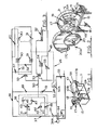
- Fig. 3 illustrates the hydraulic circuit 28 which is utilised to control operation of the power-driven components.
- the hydraulic motor for driving the knife blade 20 is denoted 30
- the hydraulic motor for driving the counterbalanced carrier 21 is denoted 31
- the hydraulic ram for driving the meat device 12B is denoted 32.
- the hydraulic circuit comprises a sump 33 into which used fluid is dumped and from which fluid is drawn by a gear pump 34 via a strainer 35, the output of pump 34 being delivered through a 10 micron filter and associated check valve 36 to a pressure-controlled manifold 37.
- Pressure control of manifold 37 is effected by control unit 38 as will be explained so that the pressure-controlled fluid is delivered at the output of manifold 37 to feed line 39 which delivers fluid to motors 30, 31 in parallel, motor 31 having a one-way check valve 40.
- Pump 34 is driven by electric motor 34A and unit 38 is provided with two parallel feeds 41, 42, the former being delivered to solenoid control valve 43 and the latter being delivered to solenoid control valve 44.
- Valve 44 is effectively OPEN/CLOSED having its output connected to sump 33 and is connected in parallel with relief valve 46 the output of which delivers to line 50 which is pressure controlled by relief valve 51 delivering to sump 33 via heat exchanger 52 and lO micron filter 52A.
- Valve 43 is a three position valve delivering in its two OPEN positions to one or other of two relief valves 45, 47 the output of each of which delivers to line 50.
- control unit 38 The operation of control unit 38 is such that when valve 44 is in its OPEN position the fluid delivered by pump 34 is dumped directly to sump 33 and the pressure in manifold 37 is substantially zero.
- valve 44 When valve 44 is in its CLOSED position the pressure in manifold 37 is governed by relief valve 46 which is set at approximately 100 bar provided valve 43 is in its CLOSED position.
- relief valve 46 which is set at approximately 100 bar provided valve 43 is in its CLOSED position.
- valve 43 is held in its CLOSED position so long as the temperature of the hydraulic fluid in sump 33 is below a preset optimum level as measured by a thermistor sensor (not shown).
- valve 47 is set at approximately 80 bar whereas valve 45 is set at approximately 60 bar.
- pressure pertaining in feed line 39 is determined by the lowest pressure setting of the operable one or ones of valves 45, 46, 47 and in each instance the pressure pertaining in line 50 is determined by relief valve 51 which is set at approximately 14 bar.
- Line 50 delivers pressurised fluid (at 14 bar) to ram 32, which is double acting, via FORWARD/REVERSE solenoid valve 53 ram velocity being controlled in either direction by flow controller 54 whilst solenoid valve 55 functions as an ON/OFF controller insofar as movement of meat device 12B towards station 15 is effected by pressurising the rear of the ram piston (valve 53 being in the position illustrated), reverse movement of device 12B away from station 15 being automatic.
- Feed line 39 delivers pressurised fluid (at 100 bar or 80 bar or 60 bar) to motors 30, 31 in parallel, the respective rotational speeds of which are governed by flow controllers 60, 61 the outputs of which deliver to a three-position solenoid valve 59 having a single output connected to line 50.
- Valve 59 acts as a SINGLE MOTOR/ STOP/DUAL MOTOR controller by virtue of the existence of check valve 58 and relief pressure valve 57. In its uppermost position valve 59 connects the line containing flow controller 60 to line 50 whilst the line containing flow controller 61 is blocked, pressure balance being achieved through relief valve 57.
- valve 59 blocks both lines from motors 30, 31 pressure balance for each being achieved via relief valve 57 if so required (as will be explained).
- valve 59 connects the line containing controller 61 to line 50 whilst the line containing controller 60 is blocked but flow of fluid is maintained via check valve 58 so that both motors 30, 31 are operational.
- Lubrication fluid in motors 30, 31 is provided by the feed 39 and this fluid is drained to sump by drain line 48.
- solenoid valve 43 When the hydraulic fluid temperature is less than a preset nominal value solenoid valve 43 is electrically interlocked in its central CLOSED position so that relief valves 45, 47 are non- operational and normal slicing operation of the machine lO ensues with valve 44 in its CLOSED position. If the machine 10 requires to be manually powered down this is effected by activation of an ON/OFF button (not shown) which moves valve 44 to its OPEN position and at a fixed time interval thereafter (for example 4 seconds) pump motor 34A is de-energised.
- ON/OFF button not shown
- valve 44 is de-energised simultaneously with valve 44 being moved to its OPEN position.
- cavitation of the hydraulic fluid in the hydraulic system is prevented by a check valve 49 interconnecting lines 50 and 39.
- valve 43 is disinhibited and is signalled into one or other of its OPEN positions as previously explained by the movement of the meat table 12 such that when the device 12B is moving towards station 15 relief valve 47 is operable to provide 80 bar pressure in line 39 but when device 12B moves away from station 15 relief valve 45 is operable to provide 60 bar pressure in line 39.
- the rotational speed of carrier 21 is monitored by a proximity detector and in the event that the carrier rotational speed drops by a predetermined amount (for example 80 revs/min) with relief valve 47 operable solenoid valve 43 is moved to its central position in order to render relief valve 46 operational at 100 bar. This event may occur when the product being sliced is unexpectedly tough.
- the hydraulic system described is relatively simple in concept and facilitates the use of standard off-the-shelf components namely flow controllers, two position solenoid valves, three position solenoid valves and relief valves so that the system may be rendered modular if so desired.
- the associated electrical control system if so desired may also be modular and embodied in hard-wired logic elements or soft-ware logic (i.e. microprocessor).
- the system is advantageous in that the slicing power is controlled so that commercially acceptable slicing can be effected immediately from start-up of the machine.
Landscapes
- Life Sciences & Earth Sciences (AREA)
- Forests & Forestry (AREA)
- Engineering & Computer Science (AREA)
- Mechanical Engineering (AREA)
- Fluid-Pressure Circuits (AREA)
- Processing Of Stones Or Stones Resemblance Materials (AREA)
Applications Claiming Priority (2)
| Application Number | Priority Date | Filing Date | Title |
|---|---|---|---|
| GB8208880 | 1982-03-26 | ||
| GB8208880 | 1982-03-26 |
Publications (2)
| Publication Number | Publication Date |
|---|---|
| EP0090623A2 true EP0090623A2 (fr) | 1983-10-05 |
| EP0090623A3 EP0090623A3 (fr) | 1986-07-02 |
Family
ID=10529293
Family Applications (1)
| Application Number | Title | Priority Date | Filing Date |
|---|---|---|---|
| EP83301695A Withdrawn EP0090623A3 (fr) | 1982-03-26 | 1983-03-25 | Machine à découper des plaques de produits alimentaires |
Country Status (2)
| Country | Link |
|---|---|
| EP (1) | EP0090623A3 (fr) |
| AU (1) | AU1287683A (fr) |
Cited By (4)
| Publication number | Priority date | Publication date | Assignee | Title |
|---|---|---|---|---|
| GB2325615A (en) * | 1997-05-31 | 1998-12-02 | Gec Avery Ltd | Powered product table for food slicer. |
| AT408858B (de) * | 1999-03-23 | 2002-03-25 | Mgt Technics Meierhofer Gruenw | Vorrichtung zum aufschneiden von lebensmitteln |
| EP1520665A1 (fr) * | 2003-10-02 | 2005-04-06 | S.A. Jac N.V. | Dispositif de découpe automatisée de pain en tranches |
| CN110774332A (zh) * | 2019-11-29 | 2020-02-11 | 安徽华菱西厨装备股份有限公司 | 一种半交叉带传动切片机 |
Family Cites Families (4)
| Publication number | Priority date | Publication date | Assignee | Title |
|---|---|---|---|---|
| US2456431A (en) * | 1940-11-08 | 1948-12-14 | Landis Tool Co | Valve means to compensate for viscosity in hydraulic systems |
| US3140737A (en) * | 1961-01-23 | 1964-07-14 | Mayer & Co Inc O | Slicer feed control apparatus |
| US3855889A (en) * | 1972-12-04 | 1974-12-24 | Leo S Quality Foods | Slicer |
| US3974725A (en) * | 1974-07-08 | 1976-08-17 | A. Duda And Sons | High volume cutter for elongate food products |
-
1983
- 1983-03-25 AU AU12876/83A patent/AU1287683A/en not_active Abandoned
- 1983-03-25 EP EP83301695A patent/EP0090623A3/fr not_active Withdrawn
Cited By (5)
| Publication number | Priority date | Publication date | Assignee | Title |
|---|---|---|---|---|
| GB2325615A (en) * | 1997-05-31 | 1998-12-02 | Gec Avery Ltd | Powered product table for food slicer. |
| AT408858B (de) * | 1999-03-23 | 2002-03-25 | Mgt Technics Meierhofer Gruenw | Vorrichtung zum aufschneiden von lebensmitteln |
| EP1520665A1 (fr) * | 2003-10-02 | 2005-04-06 | S.A. Jac N.V. | Dispositif de découpe automatisée de pain en tranches |
| WO2005030445A1 (fr) * | 2003-10-02 | 2005-04-07 | S.A. Jac N.V. | Dispositif de decoupe automatisee de pain en tranches |
| CN110774332A (zh) * | 2019-11-29 | 2020-02-11 | 安徽华菱西厨装备股份有限公司 | 一种半交叉带传动切片机 |
Also Published As
| Publication number | Publication date |
|---|---|
| EP0090623A3 (fr) | 1986-07-02 |
| AU1287683A (en) | 1983-09-29 |
Similar Documents
| Publication | Publication Date | Title |
|---|---|---|
| US5088532A (en) | Material feed control method and apparatus for a wood or brush chipping machine | |
| US5697275A (en) | Slicing station, with shear edge member, for a food loaf slicing machine | |
| US5186398A (en) | Paper shredder | |
| CA2154337C (fr) | Machine a decouper des pains de viande ou autre | |
| US6814320B1 (en) | Reversing automatic feed wheel assembly for wood chipper | |
| US5784937A (en) | Three dimensional automatic food slicer | |
| US4015494A (en) | Cold cut slicing system | |
| US4529134A (en) | Self-clearing shredding apparatus and method of operation thereof | |
| EP1261249B1 (fr) | Commandes d'alimentation pour recolteuse-hacheuse de fourrage | |
| US3524485A (en) | Log chipping apparatus | |
| EP0248354A3 (en) | Slicer | |
| US4441411A (en) | Slicer for ham or the like | |
| CA2541555A1 (fr) | Dispositif et methode de decoupage de produits alimentaires | |
| US3855889A (en) | Slicer | |
| US4434692A (en) | Grid-type bread-slicing machine | |
| US3939749A (en) | Band saw | |
| US4344341A (en) | Slicing apparatus | |
| EP0271194A2 (fr) | Trancheuse ayant des caractéristiques d'empilage modifiées | |
| US4821635A (en) | Meat slicing apparatus | |
| US3954035A (en) | Slicing machine having feed means synchronized with knife rotation | |
| US4312252A (en) | Food slicers | |
| EP0090623A3 (fr) | Machine à découper des plaques de produits alimentaires | |
| US4181053A (en) | Food slicers | |
| US4177703A (en) | Slicing machine for salmon | |
| FI72895C (fi) | Foerfarande och anordning foer disintegrering av material. |
Legal Events
| Date | Code | Title | Description |
|---|---|---|---|
| PUAI | Public reference made under article 153(3) epc to a published international application that has entered the european phase |
Free format text: ORIGINAL CODE: 0009012 |
|
| AK | Designated contracting states |
Designated state(s): DE GB NL SE |
|
| PUAL | Search report despatched |
Free format text: ORIGINAL CODE: 0009013 |
|
| AK | Designated contracting states |
Kind code of ref document: A3 Designated state(s): DE GB NL SE |
|
| STAA | Information on the status of an ep patent application or granted ep patent |
Free format text: STATUS: THE APPLICATION IS DEEMED TO BE WITHDRAWN |
|
| 18D | Application deemed to be withdrawn |
Effective date: 19870103 |
|
| RIN1 | Information on inventor provided before grant (corrected) |
Inventor name: ESCHER, ROBERT THEODOOR |