EP0090687A1 - Vorrichtung zur Katheterisierung für die Verwendung in der Human- und Tiermedizin - Google Patents
Vorrichtung zur Katheterisierung für die Verwendung in der Human- und Tiermedizin Download PDFInfo
- Publication number
- EP0090687A1 EP0090687A1 EP83400442A EP83400442A EP0090687A1 EP 0090687 A1 EP0090687 A1 EP 0090687A1 EP 83400442 A EP83400442 A EP 83400442A EP 83400442 A EP83400442 A EP 83400442A EP 0090687 A1 EP0090687 A1 EP 0090687A1
- Authority
- EP
- European Patent Office
- Prior art keywords
- tubing
- needle
- tube
- clamp
- connector
- Prior art date
- Legal status (The legal status is an assumption and is not a legal conclusion. Google has not performed a legal analysis and makes no representation as to the accuracy of the status listed.)
- Withdrawn
Links
- 230000010412 perfusion Effects 0.000 title claims description 3
- 239000003814 drug Substances 0.000 title 1
- 230000005641 tunneling Effects 0.000 claims abstract description 25
- 230000000295 complement effect Effects 0.000 claims description 3
- 239000008188 pellet Substances 0.000 claims description 3
- 229910001220 stainless steel Inorganic materials 0.000 claims description 3
- 239000010935 stainless steel Substances 0.000 claims description 3
- 210000004204 blood vessel Anatomy 0.000 claims description 2
- 230000006835 compression Effects 0.000 claims description 2
- 238000007906 compression Methods 0.000 claims description 2
- 239000013013 elastic material Substances 0.000 claims description 2
- 238000001802 infusion Methods 0.000 abstract description 7
- 238000000034 method Methods 0.000 description 6
- 230000002787 reinforcement Effects 0.000 description 6
- 239000002184 metal Substances 0.000 description 4
- 238000010586 diagram Methods 0.000 description 3
- 239000000463 material Substances 0.000 description 3
- KWGRBVOPPLSCSI-WPRPVWTQSA-N (-)-ephedrine Chemical compound CN[C@@H](C)[C@H](O)C1=CC=CC=C1 KWGRBVOPPLSCSI-WPRPVWTQSA-N 0.000 description 2
- 206010001526 Air embolism Diseases 0.000 description 2
- 239000002390 adhesive tape Substances 0.000 description 2
- 244000052616 bacterial pathogen Species 0.000 description 2
- 238000011109 contamination Methods 0.000 description 2
- 238000002788 crimping Methods 0.000 description 2
- 210000005069 ears Anatomy 0.000 description 2
- 229920001971 elastomer Polymers 0.000 description 2
- MSKQYWJTFPOQAV-UHFFFAOYSA-N fluoroethene;prop-1-ene Chemical group CC=C.FC=C MSKQYWJTFPOQAV-UHFFFAOYSA-N 0.000 description 2
- 230000035515 penetration Effects 0.000 description 2
- 239000004033 plastic Substances 0.000 description 2
- 229920003023 plastic Polymers 0.000 description 2
- -1 polytetrafluoroethylene Polymers 0.000 description 2
- 229920001343 polytetrafluoroethylene Polymers 0.000 description 2
- 239000004810 polytetrafluoroethylene Substances 0.000 description 2
- 229920002635 polyurethane Polymers 0.000 description 2
- 239000004814 polyurethane Substances 0.000 description 2
- 239000007787 solid Substances 0.000 description 2
- 229920003051 synthetic elastomer Polymers 0.000 description 2
- 239000004698 Polyethylene Substances 0.000 description 1
- 238000013459 approach Methods 0.000 description 1
- 210000003323 beak Anatomy 0.000 description 1
- 239000008280 blood Substances 0.000 description 1
- 210000004369 blood Anatomy 0.000 description 1
- 239000000470 constituent Substances 0.000 description 1
- 238000012631 diagnostic technique Methods 0.000 description 1
- 230000002526 effect on cardiovascular system Effects 0.000 description 1
- 239000000806 elastomer Substances 0.000 description 1
- 230000007613 environmental effect Effects 0.000 description 1
- 239000000284 extract Substances 0.000 description 1
- 229920002457 flexible plastic Polymers 0.000 description 1
- 238000009434 installation Methods 0.000 description 1
- 238000001990 intravenous administration Methods 0.000 description 1
- 230000007774 longterm Effects 0.000 description 1
- 239000002985 plastic film Substances 0.000 description 1
- 229920000573 polyethylene Polymers 0.000 description 1
- 229920001296 polysiloxane Polymers 0.000 description 1
- QQONPFPTGQHPMA-UHFFFAOYSA-N propylene Natural products CC=C QQONPFPTGQHPMA-UHFFFAOYSA-N 0.000 description 1
- 125000004805 propylene group Chemical group [H]C([H])([H])C([H])([*:1])C([H])([H])[*:2] 0.000 description 1
- 238000010992 reflux Methods 0.000 description 1
- 230000003014 reinforcing effect Effects 0.000 description 1
- 238000005070 sampling Methods 0.000 description 1
- 238000000926 separation method Methods 0.000 description 1
- 238000004659 sterilization and disinfection Methods 0.000 description 1
- 210000001321 subclavian vein Anatomy 0.000 description 1
- 230000000472 traumatic effect Effects 0.000 description 1
- 230000002792 vascular Effects 0.000 description 1
- 230000002747 voluntary effect Effects 0.000 description 1
Images


Classifications
-
- A—HUMAN NECESSITIES
- A61—MEDICAL OR VETERINARY SCIENCE; HYGIENE
- A61M—DEVICES FOR INTRODUCING MEDIA INTO, OR ONTO, THE BODY; DEVICES FOR TRANSDUCING BODY MEDIA OR FOR TAKING MEDIA FROM THE BODY; DEVICES FOR PRODUCING OR ENDING SLEEP OR STUPOR
- A61M25/00—Catheters; Hollow probes
- A61M25/0009—Making of catheters or other medical or surgical tubes
- A61M25/0014—Connecting a tube to a hub
-
- A—HUMAN NECESSITIES
- A61—MEDICAL OR VETERINARY SCIENCE; HYGIENE
- A61M—DEVICES FOR INTRODUCING MEDIA INTO, OR ONTO, THE BODY; DEVICES FOR TRANSDUCING BODY MEDIA OR FOR TAKING MEDIA FROM THE BODY; DEVICES FOR PRODUCING OR ENDING SLEEP OR STUPOR
- A61M25/00—Catheters; Hollow probes
- A61M25/01—Introducing, guiding, advancing, emplacing or holding catheters
- A61M25/06—Body-piercing guide needles or the like
Definitions
- the present invention relates to a catheterization device, usable for perfusions in the medical and veterinary fields.
- this device comprises a catheter with flexible tubing and means for "tunneling" this tubing under the skin of the patient over a determined distance between a point of puncture of a blood vessel and the external surface of the skin of the patient.
- the catheter also includes a connection junction from the outer end of the tubing to an outer supply line, while the "tunneling" means comprise a needle which is integral with the end of the tubing and intended to be separated from this last after tunneling to allow attachment of the connector to the tubing.
- Catheters for intravenous or peritoneal infusions comprising generally flexible tubing inserted through the lumen of a puncture needle, are well known, such a catheter being described for example in French Patent No. 1,064,445 .
- catheters when it is necessary to leave such catheters in place for a long time, several weeks or several months, or under special environmental conditions, it is noted that these catheters risk allowing contamination of the patient by ambient germs which will use the initial puncture point to reach the vascular system of the patient. It is also noted that such catheters are liable to separate either from the patient or from the infusion set, for example during movements which the patient may unconsciously make.
- one solution consists in making follow the catheter, between the puncture point of the vessel and the external surface of the patient, not the shortest path, but a path of several centimeters, practically parallel to the patient's skin, a few millimeters below the skin. Under these conditions, the external germs are forced to progress in a large part of poorly vascularized flesh which forms a natural obstacle to their progression.
- this technique called "tunneling" requires the use of pliers with long beaks, or large needles, in conditions often traumatic either for the patient or for the tubing of the catheters.
- the object of the invention is to remedy these drawbacks by producing a catheter associated with means to "tunnel" the tubing thereof easily, and to securely connect this catheter to the selected outer tubing.
- the "tunneling" means used by the invention include a needle secured to one end of the tubing and intended to be separated from the latter after the tunneling to allow the fitting of the connector to the tubing.
- French patent 2,202,706 describes a device for fixing a needle on a flexible tube. This fixing is ensured by crimping the corresponding end of this needle on the respective end of the corresponding tubing after having placed inside the latter a solid piece of reinforcement in malleable metal. Thus the crimping of the end of the needle causes a constriction of this solid piece of reinforcement and the joining of the needle with the tubing results from the deformation imposed on this tubing due to the deformation and the constriction of the full internal part.
- a solution cannot be envisaged for the catheterization device according to the invention.
- the needle is fixed to the corresponding tubing by a fixing device comprising a rigid tube, for example made of stainless steel, the internal diameter of which is equal to that of the flexible tubing, embedded in the end of this tubing, the needle having, with regard to this tube, a constriction ensuring the compression and the jamming of the end of this tubing against the tube without causing a narrowing of the internal diameter of the tubing, which ensures a perfect joining of this tubing with the needle of tunneling.
- a fixing device comprising a rigid tube, for example made of stainless steel, the internal diameter of which is equal to that of the flexible tubing, embedded in the end of this tubing, the needle having, with regard to this tube, a constriction ensuring the compression and the jamming of the end of this tubing against the tube without causing a narrowing of the internal diameter of the tubing, which ensures a perfect joining of this tubing with the needle of tunneling.
- the catheter itself is constituted by the assembly of the flexible tubing 3 and the connector 7, 8 after the tunneling operation.
- flexible tubing 3 made of polytetrafluoroethylene, or of polyurethane, or of rubber elastomer can be chosen.
- a tubing 3 made of fluoroethylene propylene with an outside diameter equal to 1.67 mm and an inside diameter of 1.07 mm.
- the guide 2 intended to allow the introduction of the tube 3 can then have a diameter of 0.89 mm, which will allow easy sliding of the tube 3 which must slide on the guide 2.
- the end 4 of the tube 3 has an adequate finish to facilitate penetration of this tube through the puncture point of the superficial tissues of the vessel to be catheterized.
- the needle 5 must be fixed on the tube 3 without causing the lumen of the latter to narrow at the point d '' prevent easy penetration and sliding of the guide 2.
- the needle 5 is fixed to the tube 3 by a device preventing any narrowing of the lumen of the tube 3 at its junction with the needle 5.
- the device for fixing the needle 5 to the tubing 3 comprises a tube rigid 17 whose internal diameter d is equal to that of the tubing 3.
- the end 11 of the tubing 3 is thus embedded between the rigid internal annular reinforcement 17 and the needle 5 which has, facing the reinforcing tube 17, a constriction 12 which secures the needle 5 with the tube 3 without causing a narrowing of the internal diameter of the latter.
- This solution is particularly suitable for securing a PTFE or fluoroethylene propylene tubing, given the difficulties of bonding these materials to stainless steel.
- the diameter d of the tube 17 is equal to that of the tube 3, therefore is 1.07 mm, its outside diameter being 1.27 mm and its length being 10 mm approximately.
- the constriction 12 can then have an external diameter of 2.00 mm, while the cylindrical body of the needle 5 can have an external diameter of 2.20 mm and a length of approximately 5 to 15 mm.
- this internal reinforcement operation can possibly be replaced by an appropriate bonding of the needle 5, which must be securely fixed to the tubing 3.
- the main thing is that the attachment of the needle 5 and the tube 3 must be carried out without going for the lumen of the latter a narrowing such that the guide 2 could no longer slide freely enough in this lumen.
- the mandrel 6 also makes it possible to prevent the cutting heel of the bevel 5a of the needle 5 from being able to cut pieces of flesh during the progression of this needle 5 under the patient's skin.
- the length and the outside diameter of the shutter mandrel 6 must be chosen according to the position fixed for the end 11 of the tube 3 in the constricted part 12 of the needle 5, and the characteristics of the latter.
- the length of the mandrel 6 must be substantially equal to the distance existing between the end 18 (FIG. 3) of the tube 3, located inside the needle 5, and the heel 5a of this same needle 5.
- This mandrel 6 can preferably be given a cross section perpendicular to its axis for the end intended to come to bear on the part 18 of the tube 3.
- the mandrel 9 is intended to facilitate the positioning of the tubular connection 7, 8 in the lumen of the end of the tubing 3 after cutting of the latter once the tunneling operation has ended.
- the body of the connector 7 is provided in known manner with two lateral ears 16 each pierced with a hole 16a.
- the connector 7 is provided with a clamp or "clamp” 13 ( Figures 1 and 5 to 7), capable of clamping the end 4a of the tube 3, opposite the end 4 introduced into the vessel, on the rigid tubular part 8 of the connector 7, and this after execution of the tunneling and separation of the needle 5 and the tube 3 by cutting the end of the latter.
- the clamp 13 is arranged to prevent any relative sliding between the tubular part 8 and the tubing 3, and to be firmly secured with the fitting 7.
- the clamp 13 is formed of a housing in 2 parts 13a, 13b, articulated around a hinge 26 formed for example of a flexible plastic film. These two parts can be closed one on the other and the closure maintained for example by means of two lugs 27 formed laterally on the part 13a and which snap onto the ends of a corresponding projecting flange 28, s' extending along part 13b.
- the branch 13b of the clamp 13 is provided, at its end facing the connector 7, with a step 30 pierced with an opening 40 for passage for the body of the connector 7.
- the step 30 is adapted to come into an annular groove 14 formed in the end part of the body of the connector 7, on the side of the tubular part 8, so that the closure of the housing constituting the clamp 13 secures the latter of firmly with connection 7.
- Each part 13a, 13b of the housing is provided internally with a pad 21 made of a suitable elastic material, such as a synthetic elastomer or rubber, this pad being housed respectively in a recess 20 of the branches 13a, 13b.
- a pad 21 made of a suitable elastic material, such as a synthetic elastomer or rubber, this pad being housed respectively in a recess 20 of the branches 13a, 13b.
- Complementary grooves 22 are provided in each of the ends of the parts 13a, 13b, beyond the pellets 21, to receive the end of the rigid tubular part 8. Furthermore, on either side of one of the grooves 22, for example that which is formed in the branch 13b, a pair of lugs 24 is arranged so as to be able to fit into corresponding holes 25 formed on the edges of the groove 22 of the other branch 13a, when closing of the housing 13. Finally, the grooves 22 have flares 22a at their outlet ends in order to avoid damaging the tube 3.
- the assembly is as illustrated in FIG. 7: the step 30 is engaged in the throttled part formed by the groove 14, which is connected to the tubular part 8 by a conical section 41, so that the connector 7 is locked in position against the branch 13b.
- the tubular part 8 bears on the pellet 21 and extends in the groove 22.
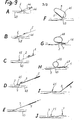
- the practitioner After careful skin disinfection, the practitioner approaches the vessel 43 to be catheterized, for example a subclavian vein or an internal jugular, with needle 1, the length of which can be approximately 8 cm, mounted on a 10 cm 3 syringe 44.
- vessel 43 for example a subclavian vein or an internal jugular, with needle 1, the length of which can be approximately 8 cm, mounted on a 10 cm 3 syringe 44.
- the practitioner withdraws the syringe 44 and introduces into the needle 1 the metallic spiral guide 2, over fifteen centimeters. The practitioner then withdraws needle 1 (Phase C ) and discards it.
- the practitioner slightly enlarges the cutaneous orifice 45 of emergence of the metal guide 2 and introduces the tubing 3 on this guide 2 by pushing in the flexible end 4 devoid of needle, the end opposite being provided with the needle 5.
- the practitioner positions the tubing 3 according to the Seldinger method. Markings on the tubing 3 indicate to the practitioner the length of tubing introduced.
- the practitioner removes the metal guide 2, then fully introduces the obturator mandrel 6 made of plastic material, with a length of about 7 cm, into the needle 5.
- the mandrel 6 avoids the risks of gas embolism and prevents a possible cutting of pieces of tissue from the patient during the tunneling operation of the tubing 3.
- the practitioner extracts the needle 5 from the emergence orifice 47 and pulls on the latter, gently driving the tubing 3 secured to the needle, and until the loop 48 which has formed at the point completely disappears initial puncture 45.
- the practitioner ensures that there is no skin bridge under the catheter at the initial puncture point 45, and that there is also no tubing 3, a plication that can hinder the flow of infusions.
- the practitioner cuts the tubing 3 about 1 cm from the crimped needle 5, and discards the latter. He adapts the female "luer-lock" fitting 7, by fully inserting the assembly constituted by the fitting 7, 8 and the mandrel 9 into the tubing 3. Then the practitioner removes the mandrel 9 and its crankpin 10 and throws it away.
- the clamp 13 is then closed by folding of the branch 13a with introduction of the pins or pins 24 into the holes 25 and snap-fastening of the pins 27 on the bar 28.
- the fitting 7 can now be connected to the chosen external tubing.
- the catheter and the tunneling means which have just been described have two essential advantages: on the one hand, the attachment of the needle 5 with the tubing 3 is carried out so as to prevent any narrowing of the lumen of the tubing 3 liable to hinder the sliding of guide 2; on the other hand, the clamp 13 is arranged in such a way that it ensures perfect attachment of the flexible tubing 3 to the rigid part 8 of the connector 7, preventing any relative sliding between these parts. In addition, the clamp 13 is very securely attached to the connector 7, which can only be detached from the clamp by a voluntary operation of opening the latter by releasing the pins 27 from the retaining bar 28.
- the reinforcement tube 17 must project relative to the end 18 of the tubing 3 by a minimum distance of 1 mm before performing the constriction 12; this avoids a narrowing of the lumen of the tube 3 by the end 18.
- the end 12a of the constriction 12 must be set back relative to the end 17a of the reinforcement tube 17, for the same reason.
- the catheter according to the invention allows tunneling to be easily carried out and can be securely connected to the chosen external tubes.
- clamp 13 can be produced in any other way equivalent to that described.
Landscapes
- Health & Medical Sciences (AREA)
- Life Sciences & Earth Sciences (AREA)
- Biophysics (AREA)
- Pulmonology (AREA)
- Engineering & Computer Science (AREA)
- Anesthesiology (AREA)
- Biomedical Technology (AREA)
- Heart & Thoracic Surgery (AREA)
- Hematology (AREA)
- Animal Behavior & Ethology (AREA)
- General Health & Medical Sciences (AREA)
- Public Health (AREA)
- Veterinary Medicine (AREA)
- Infusion, Injection, And Reservoir Apparatuses (AREA)
- Media Introduction/Drainage Providing Device (AREA)
Applications Claiming Priority (2)
| Application Number | Priority Date | Filing Date | Title |
|---|---|---|---|
| FR8203674A FR2522504B1 (fr) | 1982-03-05 | 1982-03-05 | Dispositif de catheterisation, utilisable pour des perfusions dans les domaines medical et veterinaire |
| FR8203674 | 1982-03-05 |
Publications (1)
| Publication Number | Publication Date |
|---|---|
| EP0090687A1 true EP0090687A1 (de) | 1983-10-05 |
Family
ID=9271627
Family Applications (1)
| Application Number | Title | Priority Date | Filing Date |
|---|---|---|---|
| EP83400442A Withdrawn EP0090687A1 (de) | 1982-03-05 | 1983-03-04 | Vorrichtung zur Katheterisierung für die Verwendung in der Human- und Tiermedizin |
Country Status (4)
| Country | Link |
|---|---|
| US (1) | US4504269A (de) |
| EP (1) | EP0090687A1 (de) |
| JP (1) | JPS58163377A (de) |
| FR (1) | FR2522504B1 (de) |
Cited By (3)
| Publication number | Priority date | Publication date | Assignee | Title |
|---|---|---|---|---|
| EP0226397A3 (en) * | 1985-12-06 | 1988-03-30 | Sherwood Medical Company | Disposable catheter insertion apparatus |
| FR2671283A1 (fr) * | 1991-01-08 | 1992-07-10 | Durand Alain | Catheter multilumiere intravasculaire, susceptible d'etre implante avec tunnellisation. |
| RU2128058C1 (ru) * | 1998-06-18 | 1999-03-27 | Общество с ограниченной ответственностью "Балт-С" | Устройство для селективной катетеризации |
Families Citing this family (24)
| Publication number | Priority date | Publication date | Assignee | Title |
|---|---|---|---|---|
| US4675007A (en) * | 1985-10-03 | 1987-06-23 | Concept, Inc. | Coupling device for attachment to an end of a catheter |
| US4883474A (en) * | 1986-07-30 | 1989-11-28 | David S. Sheridan | Thoracic catheter |
| US4953548A (en) * | 1987-02-02 | 1990-09-04 | Mallinckrodt, Inc. | Laser resistant ventilating device with locking ferrule |
| US4898178A (en) * | 1987-04-24 | 1990-02-06 | Wedel Victor J | Monolithic disposable needle guide for ultrasound transducers |
| US4950252A (en) * | 1987-11-02 | 1990-08-21 | Luther Medical Products, Inc. | Single hand actuated locking safety catheter and method of use |
| JPH0294556U (de) * | 1989-01-11 | 1990-07-27 | ||
| US4973313A (en) * | 1989-09-13 | 1990-11-27 | Sherwood Medical Company | Over the needle catheter introducer |
| US6379307B1 (en) | 1998-09-16 | 2002-04-30 | Roy Filly | Adjustable needle guide apparatus and method |
| US6296614B1 (en) | 1999-04-08 | 2001-10-02 | Rick L. Pruter | Needle guide for attachment to ultrasound transducer probe |
| US7452331B1 (en) | 1999-04-08 | 2008-11-18 | Rick L Pruter | Vascular adjustable multi-gauge tilt-out method and apparatus for guiding needles |
| US6612990B1 (en) | 1999-04-08 | 2003-09-02 | Rick L. Pruter | Method and apparatus for guiding needles |
| US6468252B1 (en) | 2000-08-03 | 2002-10-22 | Sanfilippo, Ii Dominic J. | Clamp for vascular access device |
| GB0205773D0 (en) * | 2002-03-12 | 2002-04-24 | Gill Steven S | Clamp |
| US6758817B1 (en) | 2002-09-11 | 2004-07-06 | Protek Medical Products, Inc. | Method and disposable apparatus for guiding needles |
| US8353840B1 (en) | 2002-09-11 | 2013-01-15 | Pruter Rick L | Method and disposable apparatus for guiding needles with a double button unlocking and locking mechanism |
| US6884219B1 (en) | 2002-10-17 | 2005-04-26 | Rick L. Pruter | Method and disposable apparatus for guiding needles with an endocavity medical imaging device |
| US7758586B2 (en) * | 2003-05-02 | 2010-07-20 | Atrium Medical Corporation | Method and apparatus for introducing catheters |
| JP2007535385A (ja) | 2004-04-30 | 2007-12-06 | シー・アール・バード・インコーポレーテッド | 静脈挿管用の弁付き鞘導入器 |
| US7846103B2 (en) * | 2004-09-17 | 2010-12-07 | Medical Equipment Diversified Services, Inc. | Probe guide for use with medical imaging systems |
| US8403890B2 (en) * | 2004-11-29 | 2013-03-26 | C. R. Bard, Inc. | Reduced friction catheter introducer and method of manufacturing and using the same |
| US9597483B2 (en) * | 2004-11-29 | 2017-03-21 | C. R. Bard, Inc. | Reduced-friction catheter introducer and method of manufacturing and using the same |
| US8926564B2 (en) | 2004-11-29 | 2015-01-06 | C. R. Bard, Inc. | Catheter introducer including a valve and valve actuator |
| US8932260B2 (en) * | 2004-11-29 | 2015-01-13 | C. R. Bard, Inc. | Reduced-friction catheter introducer and method of manufacturing and using the same |
| EP2211971A4 (de) * | 2007-10-19 | 2014-09-10 | Bard Inc C R | Einführinstrument mit geformter distaler region |
Citations (12)
| Publication number | Priority date | Publication date | Assignee | Title |
|---|---|---|---|---|
| FR1125688A (fr) * | 1954-06-08 | 1956-11-05 | Sonde cardiaque et procédé de fabrication de cette sonde | |
| FR2012505A1 (en) * | 1968-07-08 | 1970-03-20 | Viggo Ab | Flexible plastics canule for infusion purposes - seated in metal sheath lining of polyethylene housing |
| US3568673A (en) * | 1968-11-04 | 1971-03-09 | Bard Inc C R | Needle bevel guard for intravenous catheter |
| US3574306A (en) * | 1969-01-13 | 1971-04-13 | Deseret Pharma | Needle protector |
| FR2121965A5 (de) * | 1971-01-13 | 1972-08-25 | Technological Supply Inc | |
| FR2202706A1 (de) * | 1972-10-17 | 1974-05-10 | Durand Herve T | |
| FR2263789A1 (en) * | 1974-03-13 | 1975-10-10 | Transcodan | Flexible catheter insertion nozzle - is sealed from bacteria in wing area by easily opened housing |
| FR2276066A1 (fr) * | 1974-06-24 | 1976-01-23 | Abbott Lab | Dispositif d'insertion et de maintien de canules de traitement medical |
| GB1447237A (en) * | 1973-07-31 | 1976-08-25 | Davol International Ltd | Intravenous catheter needle guards |
| GB1459741A (en) * | 1972-09-21 | 1976-12-31 | Parkinson P I | Intravenous equipment |
| EP0001106A1 (de) * | 1977-09-06 | 1979-03-21 | Johnson & Johnson | Katheteranordnung |
| GB2012595A (en) * | 1977-12-01 | 1979-08-01 | Peters J L | Safety device for use with a cannula |
Family Cites Families (7)
| Publication number | Priority date | Publication date | Assignee | Title |
|---|---|---|---|---|
| US2908053A (en) * | 1957-05-22 | 1959-10-13 | Gilman | Marquee construction |
| US3345090A (en) * | 1964-10-27 | 1967-10-03 | Weatherhead Co | Hose end fitting |
| BE788761A (fr) * | 1971-09-14 | 1973-01-02 | Raven Carl B | Ensemble de canule d'infusion |
| US4140125A (en) * | 1976-02-25 | 1979-02-20 | Med-Pro, Ltd. | Surgical tape device |
| SE401785B (sv) * | 1976-10-26 | 1978-05-29 | Viggo Ab | Anordning vid ett infusionskanylaggregat |
| US4359053A (en) * | 1980-06-05 | 1982-11-16 | Snyder Laboratories, Inc. | Means of fastening silicone tubing to a rigid surgical needle |
| US4405312A (en) * | 1981-08-31 | 1983-09-20 | Abbott Laboratories | Connecting device for medical liquid containers |
-
1982
- 1982-03-05 FR FR8203674A patent/FR2522504B1/fr not_active Expired
-
1983
- 1983-03-01 US US06/471,211 patent/US4504269A/en not_active Expired - Fee Related
- 1983-03-04 EP EP83400442A patent/EP0090687A1/de not_active Withdrawn
- 1983-03-04 JP JP58035693A patent/JPS58163377A/ja active Pending
Patent Citations (12)
| Publication number | Priority date | Publication date | Assignee | Title |
|---|---|---|---|---|
| FR1125688A (fr) * | 1954-06-08 | 1956-11-05 | Sonde cardiaque et procédé de fabrication de cette sonde | |
| FR2012505A1 (en) * | 1968-07-08 | 1970-03-20 | Viggo Ab | Flexible plastics canule for infusion purposes - seated in metal sheath lining of polyethylene housing |
| US3568673A (en) * | 1968-11-04 | 1971-03-09 | Bard Inc C R | Needle bevel guard for intravenous catheter |
| US3574306A (en) * | 1969-01-13 | 1971-04-13 | Deseret Pharma | Needle protector |
| FR2121965A5 (de) * | 1971-01-13 | 1972-08-25 | Technological Supply Inc | |
| GB1459741A (en) * | 1972-09-21 | 1976-12-31 | Parkinson P I | Intravenous equipment |
| FR2202706A1 (de) * | 1972-10-17 | 1974-05-10 | Durand Herve T | |
| GB1447237A (en) * | 1973-07-31 | 1976-08-25 | Davol International Ltd | Intravenous catheter needle guards |
| FR2263789A1 (en) * | 1974-03-13 | 1975-10-10 | Transcodan | Flexible catheter insertion nozzle - is sealed from bacteria in wing area by easily opened housing |
| FR2276066A1 (fr) * | 1974-06-24 | 1976-01-23 | Abbott Lab | Dispositif d'insertion et de maintien de canules de traitement medical |
| EP0001106A1 (de) * | 1977-09-06 | 1979-03-21 | Johnson & Johnson | Katheteranordnung |
| GB2012595A (en) * | 1977-12-01 | 1979-08-01 | Peters J L | Safety device for use with a cannula |
Cited By (4)
| Publication number | Priority date | Publication date | Assignee | Title |
|---|---|---|---|---|
| EP0226397A3 (en) * | 1985-12-06 | 1988-03-30 | Sherwood Medical Company | Disposable catheter insertion apparatus |
| FR2671283A1 (fr) * | 1991-01-08 | 1992-07-10 | Durand Alain | Catheter multilumiere intravasculaire, susceptible d'etre implante avec tunnellisation. |
| EP0494806A1 (de) * | 1991-01-08 | 1992-07-15 | Alain Jean-Marie Durand | Intravaskulärer mehrlumiger Katheter für das Implantieren mit Hilfe eines Tunnels |
| RU2128058C1 (ru) * | 1998-06-18 | 1999-03-27 | Общество с ограниченной ответственностью "Балт-С" | Устройство для селективной катетеризации |
Also Published As
| Publication number | Publication date |
|---|---|
| FR2522504B1 (fr) | 1985-07-12 |
| FR2522504A1 (fr) | 1983-09-09 |
| JPS58163377A (ja) | 1983-09-28 |
| US4504269A (en) | 1985-03-12 |
Similar Documents
| Publication | Publication Date | Title |
|---|---|---|
| EP0090687A1 (de) | Vorrichtung zur Katheterisierung für die Verwendung in der Human- und Tiermedizin | |
| EP0494806B1 (de) | Intravaskulärer mehrlumiger Katheter für das Implantieren mit Hilfe eines Tunnels | |
| FR2522508A1 (fr) | Ensemble pour l'introduction de catheters | |
| FR2710541A1 (fr) | Ensemble pour l'introduction d'un cathéter. | |
| FR2470606A1 (fr) | Dispositif perfectionne de perforation de veine | |
| FR2471195A1 (fr) | Dispositif pour introduire un catheter ou une sonde dans un vaisseau sanguin | |
| FR2710540A1 (fr) | Ensemble pour l'introduction d'un cathéter. | |
| FR2460678A1 (fr) | Ensemble de catheter pour infusions de liquide | |
| FR2622117A1 (fr) | Introducteur de catheter a canule et stylet | |
| FR2479691A1 (fr) | Canule, notamment canule a dialyse avec une pointe taillee en biseau | |
| FR2785192A1 (fr) | Dispositif de protection de la pointe de l'aiguille d'un catheter | |
| FR2540728A1 (fr) | Dispositif pour introduire un catheter | |
| FR2703909A1 (fr) | Aiguille d'injection intraveineuse à demeure, avec deux voies de passage pour le reflux du sang. | |
| FR2779939A1 (fr) | Dispositif de traitement d'un vaisseau sanguin | |
| BE1008386A5 (fr) | Catheter a tige d'aiguille transparente. | |
| FR3065163A3 (fr) | Systeme permettant d'introduire une canule tracheale dans une tracheostomie | |
| FR2734727A1 (fr) | Dispositif de protection de securite pliable pour des aiguilles de seringues | |
| FR2556225A1 (fr) | Catheter perfectionne | |
| FR2804608A1 (fr) | Dispositif pour faciliter l'enfilage d'un tube catheter sur un guide et ensemble pour la mise en oeuvre de la technique de seldinger | |
| EP4061449A1 (de) | Bidirektionale arterielle kanüle zur extrakorporalen membranoxygenierung und verfahren zur verwendung einer solchen kanüle | |
| FR2697434A1 (fr) | Dispositif pour actionner le poussoir d'une seringue en vue d'y créer une dépression, système et procédé en faisant application pour la mise en place temporaire d'un cathéter et/ou d'un fil guide. | |
| WO2019002739A1 (fr) | Poignee pour delivrance d'un stent et dispositif comprenant la poignee | |
| FR2607707A1 (fr) | Embase amovible pour catheter et catheter adapte a celle-ci | |
| FR2511600A1 (fr) | Dispositif de guidage pour faciliter l'introduction d'un catheter | |
| EP3630252A1 (de) | Orientierbarer katheter, vorrichtung und verfahren für chirurgischen eingriff |
Legal Events
| Date | Code | Title | Description |
|---|---|---|---|
| PUAI | Public reference made under article 153(3) epc to a published international application that has entered the european phase |
Free format text: ORIGINAL CODE: 0009012 |
|
| AK | Designated contracting states |
Designated state(s): BE CH DE GB IT LI NL SE Kind code of ref document: A1 Designated state(s): BE CH DE GB IT LI NL SE |
|
| 17P | Request for examination filed |
Effective date: 19840225 |
|
| STAA | Information on the status of an ep patent application or granted ep patent |
Free format text: STATUS: THE APPLICATION IS DEEMED TO BE WITHDRAWN |
|
| 18D | Application deemed to be withdrawn |
Effective date: 19850418 |