EP0090691A1 - Strahldüse deren Strahl flache und feste Schleifteilchen aufweist - Google Patents
Strahldüse deren Strahl flache und feste Schleifteilchen aufweist Download PDFInfo
- Publication number
- EP0090691A1 EP0090691A1 EP83400484A EP83400484A EP0090691A1 EP 0090691 A1 EP0090691 A1 EP 0090691A1 EP 83400484 A EP83400484 A EP 83400484A EP 83400484 A EP83400484 A EP 83400484A EP 0090691 A1 EP0090691 A1 EP 0090691A1
- Authority
- EP
- European Patent Office
- Prior art keywords
- jet
- abrasive particles
- water
- flat
- nozzle
- Prior art date
- Legal status (The legal status is an assumption and is not a legal conclusion. Google has not performed a legal analysis and makes no representation as to the accuracy of the status listed.)
- Granted
Links
Images

Classifications
-
- B—PERFORMING OPERATIONS; TRANSPORTING
- B24—GRINDING; POLISHING
- B24C—ABRASIVE OR RELATED BLASTING WITH PARTICULATE MATERIAL
- B24C7/00—Equipment for feeding abrasive material; Controlling the flowability, constitution, or other physical characteristics of abrasive blasts
- B24C7/0084—Equipment for feeding abrasive material; Controlling the flowability, constitution, or other physical characteristics of abrasive blasts the abrasive material being fed in a mixture of liquid and gas
-
- B—PERFORMING OPERATIONS; TRANSPORTING
- B24—GRINDING; POLISHING
- B24C—ABRASIVE OR RELATED BLASTING WITH PARTICULATE MATERIAL
- B24C5/00—Devices or accessories for generating abrasive blasts
- B24C5/02—Blast guns, e.g. for generating high velocity abrasive fluid jets for cutting materials
- B24C5/04—Nozzles therefor
-
- B—PERFORMING OPERATIONS; TRANSPORTING
- B24—GRINDING; POLISHING
- B24C—ABRASIVE OR RELATED BLASTING WITH PARTICULATE MATERIAL
- B24C7/00—Equipment for feeding abrasive material; Controlling the flowability, constitution, or other physical characteristics of abrasive blasts
- B24C7/0046—Equipment for feeding abrasive material; Controlling the flowability, constitution, or other physical characteristics of abrasive blasts the abrasive material being fed in a gaseous carrier
Definitions
- the present invention relates to a sandblasting nozzle with a flat jet and containing abrasive solid particles.
- It relates in particular to a blasting nozzle with water under high or very high pressure used for cleaning surfaces that are heavily fouled or covered with oxides, paint, various deposits. It also relates to a method of implementing a sandblasting nozzle for radioactive decontamination.
- a sandblasting device of this type includes an inlet device which generates a jet inside a vacuum chamber.
- a pipe which brings a mixture of air and abrasive also opens into this room. The vacuum allows the suction of the abrasive which is then incorporated into the water of the jet.
- the water is injected along the axis of the sandblasting device and the abrasive supply line opens laterally into the vacuum chamber.
- This embodiment allows a reduced size, a simple implementation and a high concentration of the water jet.
- the pipe for supplying the abrasive particles is disposed in the axis of the device and one or more ejection nozzles are arranged laterally with respect to this pipe.
- Three, four or six nozzles with cylindrical nozzles are arranged annularly and converge towards a point located towards the outlet of the sandblaster.
- This arrangement has the advantage of exposing the walls of the outlet nozzle little to the action of abrasive particles, because the mixed jet is not homogeneous. In fact, the particles are concentrated essentially in the center of the jet. In addition, the impact of the jet on the part to be cleaned is distributed over a larger surface.
- the previously known sandblasting devices have a circular trace on the part to be cleaned when its surface is presented perpendicular to the jet, semi-elliptical when this surface is presented at a lower angle of incidence. at 90 °: in the latter case the ejected abrasives have a degressive action inversely proportional to the distance from the sandblaster to the object being treated: erosion will be greater at the top of the half-ellipse.
- the present invention relates to a sandblasting nozzle which provides a flat jet and containing abrasive particles, which allows the cleaning of larger surfaces without requiring the setting in parallel with several circular jet sandblasting devices.
- the nozzle from the in - vention for the decontamination of radioactive parts by means of a jet formed from a mixture of water and abrasive particles characterized in that it comprises an input device known type, capable of generating a single jet of flat water, with an opening angle a in the plane of the jet, inside a vacuum chamber, an outlet member having, in planes perpendicular to the jet flat, two diverging side walls substantially of opening ⁇ and, on either side of the flat jet, two converging walls forming an angle ⁇ , said outlet member forming an integral part of the vacuum chamber, and the combination of angles a and ⁇ and of the section of the outlet orifice being defined so that there occurs in the chamber a sufficient depression entraining the abrasive particles and orienting them so that the bombardment of the walls and of the outlet member is nonexistent when the regularity of the grains of abra sifs is constant.
- the subject of the invention is a method of using a sandblasting nozzle for radioactive decontamination, characterized in that abrasive particles soluble in water are used.
- these abrasive particles are made of boron trioxide.
- the inventor has shown that it was possible provided that suitable process parameters and adaptable structures were adopted, making it possible to obtain high flow rates and to avoid the risks of blockage of the pipes.
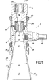
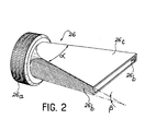
- Figures 1 and 2 There is shown in Figures 1 and 2 a first embodiment of a sandblasting nozzle 2 produced according to the invention.
- Figure 1 is a sectional view of this sandblasting nozzle
- Figure 2 is a perspective view of the outlet member which is an integral part of the sandblasting nozzle.
- the nozzle 2 comprises a body 4 of cylindrical shape. Inside the body 4 there is a circular chamber 6 which has a cylindrical part drique prolonged by a conical part which widens. The angle of the conical part 8 is approximately equal to the ejection angle of the flat jet nozzle 18. At one end of the body 4 is made an internal thread in which the inlet block 10 is screwed high pressure water. The block 10 is immobilized with respect to the body 4 by a lock nut 12 "An internal thread 14 allows the connection of the connector of the high pressure water supply pipe (not shown). This pipe brings the water into the internal channel 16 which itself opens onto an ejection nozzle 18 screwed into the block 10. The nozzle 18 has an outlet orifice 20.
- the section of this orifice is determined so as to produce a flat jet. Ejection of this kind is known.
- SOCOFREN markets ejection nozzles which can be used to carry out the invention.
- the ejection nozzle 18 is screwed onto the inlet block 10.
- a lock nut 22 makes it possible to block it in rotation relative to the body 10.
- An O-ring 24 seals between the body 10 and the ejection nozzle 18.
- the outlet member 26 At the other end of the body 4 is the outlet member 26. It is screwed onto an external thread of the body 4. It has for this purpose a knurled portion 26a. A lock nut 28 ensures its locking in rotation relative to the body 4.
- the outlet member 26 which has two diverging side walls, substantially opening a, located in planes perpendicular to the flat jet and two converging walls 26c forming an angle P.
- the interior 9 of the outlet member 26 integral part of the vacuum chamber.
- the sanding device 2 also includes a pipe 29 for supplying the abrasive particles.
- the pipe 29 is terminated by an inlet connector 30 screwed onto the body 4.
- the connector 30 opens out inside the suction chamber 6. It is arranged, in the embodiment of FIG. 1, perpendicularly to the longitudinal axis of the body 4.
- the combination of the angles a and ⁇ and of the section of the outlet orifice 26 are defined so that there is a sufficient vacuum in the chamber which entrains the abrasive particles and directs them so that the bombardment of the walls and the outlet member is nonexistent when the regularity of the abrasive grains is constant.
- the abrasive particles are introduced via line 29 carrying a gas-abrasive particle mixture, the gas possibly being air.
- the ejection nozzle 18 and the outlet member 26 must be positioned angularly with respect to each other, so that the flat jet is aligned with the orifice of the member 26. This angular positioning can be easily carried out by means of the locknuts 22 and 28 which make it possible to block the ejection nozzle 18 and the outlet member 26 respectively in any position.
- the pressurized water is brought through the nozzle 20 of the ejection nozzle 18 inside the vacuum chamber 6.
- This vacuum allows the suction, inside the chamber 6, of the mixture of air and abrasive particles brought in through line 28.
- the abrasive particles get mixed gent to the water jet and the mixed jet, that is to say the air-solid particles-water mixture, passes through the outlet nozzle 26.
- the ejection nozzle 18 of known embodiment gives a flat jet.
- the thinner plane of the outlet member 26 approximately coincides with the median plane of the high pressure flat water jet.
- the interior of the outlet member 26 is an integral part of the vacuum chamber 6.
- an additional part comprising a cavity forming an elbow allows the fitting of a connection inlet for the mixture.
- This part is fixed, for example by screws, to the body 4.
- This added part has a long resistance to wear by abrasion in the elbow, due to the thickness of its walls.
- FIG. 3 shows a second improved embodiment of the sanding device of the invention.
- This sanding nozzle 102 differs from the sanding nozzle 2 shown in FIG. 1 in that the supply line for the air-abrasive particle mixture is disposed in the axis of the body 104, while the ejection nozzle 118 , which is unique, is arranged laterally to this pipe.
- the parts which have the same function as that of the nozzle 2 in FIG. 1 have been designated by the same reference numbers increased by 100. Their description will therefore not be repeated in detail.
- the angle formed by the median plane of the flat water jet delivered by the nozzle 120 and the axis of the supply line for the air-solids mixture must be as small as possible.
- the arrival of water under high pressure is done by the cylindrical body 104.
- This supply pipe is fixed in this body 104 to the thread 114.
- a conduit 116 brings the water under high pressure to the ejection nozzle 118 screwed into the body 104.
- a lock nut 122 allows the rotational positioning of the ejection nozzle 118. It is thus possible to position this nozzle so that the longitudinal axis of the nozzle 120 is aligned with the orifice of the outlet member 126.
- the angular position of the nozzle 122 can be adjusted by means of a lock nut 112.
- the vacuum chamber essentially consists of the interior 109 of the member 126.
- the wall 126b of the outlet member 126 is substantially parallel to the median plane of the flat jet coming from the ejection nozzle 118.
- the wall 126b ' is substantially parallel, in turn, to the axis of the air-abrasive particles mixture from insert 132.
- the embodiment of Figure 3 has a double advantage.
- the arrival of the air-abrasive particles mixture takes place axially without pressure loss by taking advantage of the initial speed of the mixture.
- the angle between the axis of the supply line of the air-abrasive particles mixture and the axis of the water jet is small (less than 15 °). This eliminates the risk of clogging.
- the axial arrival of the air-solids mixture makes it possible to use a forced supply of compressed air which increases the possibilities of transporting the abrasive particles as well as the speed of ejection of the final air-water-solid particles mixture.
- the sanding nozzle of the invention described with reference to the figures has been designed so as to minimize the risk of clogging. These are particularly important when the solid abrasive used is a soluble abrasive such as boron trioxide B 2 O 3 , which is particularly advantageous in radioactive decontamination.
- the abrasive particles are in solid form during the sanding operation, which allows them to fulfill their role of abrasive. They then dissolve in water. This makes it possible to separate, by filtering, on the one hand, the metallic particles originating from the removal of the contaminated layer and, on the other hand, the water containing abrasive particles that have been dissolved. Solid particles, metallic or otherwise, are treated, then conditioned and stored. The effluents are treated before their rejection by possible recycling.
Landscapes
- Engineering & Computer Science (AREA)
- Mechanical Engineering (AREA)
- Perforating, Stamping-Out Or Severing By Means Other Than Cutting (AREA)
- Nozzles (AREA)
Applications Claiming Priority (2)
| Application Number | Priority Date | Filing Date | Title |
|---|---|---|---|
| FR8204336A FR2523019B1 (fr) | 1982-03-15 | 1982-03-15 | Buse de sablage a jet plat et contenant des particules solides abrasives, et procede de mise en oeuvre d'une buse de sablage pour la decontamination radioactive |
| FR8204336 | 1982-03-15 |
Publications (2)
| Publication Number | Publication Date |
|---|---|
| EP0090691A1 true EP0090691A1 (de) | 1983-10-05 |
| EP0090691B1 EP0090691B1 (de) | 1987-11-04 |
Family
ID=9272005
Family Applications (1)
| Application Number | Title | Priority Date | Filing Date |
|---|---|---|---|
| EP83400484A Expired EP0090691B1 (de) | 1982-03-15 | 1983-03-09 | Strahldüse deren Strahl flache und feste Schleifteilchen aufweist |
Country Status (4)
| Country | Link |
|---|---|
| US (1) | US4633623A (de) |
| EP (1) | EP0090691B1 (de) |
| DE (1) | DE3374282D1 (de) |
| FR (1) | FR2523019B1 (de) |
Cited By (5)
| Publication number | Priority date | Publication date | Assignee | Title |
|---|---|---|---|---|
| EP0582191A1 (de) * | 1992-08-03 | 1994-02-09 | Johann Szücs | Vorrichtung und Verfahren für die Behandlung von empfindlichen Oberflächen, insbesondere von Skulpturen |
| TR28484A (tr) * | 1993-10-27 | 1996-09-02 | Johann Szucs | Hassas yüzeylerin,özellikle heykellerin muamele edilmesine mahsus tertibat ve usul. |
| GB2348722A (en) * | 1999-04-07 | 2000-10-11 | Samsung Electronics Co Ltd | A memory module system having memory modules connected via switches to a data bus line |
| KR101123429B1 (ko) * | 2003-12-30 | 2012-06-29 | 바조팜 게엠베하 | 4-아미노-7,8-다이하이드로프테리다인, 이를 함유한 약학조성물 및 산화 질소 수준의 증가에 의해 야기되는 질병의치료를 위한 이의 용도 |
| EP3104097A1 (de) * | 2015-06-09 | 2016-12-14 | Services Genevois de Chauffage | Wartungsinstrument für einen brennwertkessel |
Families Citing this family (45)
| Publication number | Priority date | Publication date | Assignee | Title |
|---|---|---|---|---|
| US4648215A (en) * | 1982-10-22 | 1987-03-10 | Flow Industries, Inc. | Method and apparatus for forming a high velocity liquid abrasive jet |
| CA1231235A (en) * | 1982-10-22 | 1988-01-12 | Mohammed Hashish | Method and apparatus for forming a high velocity liquid abrasive jet |
| GB2191127A (en) * | 1986-06-02 | 1987-12-09 | Laing & Sons Ltd James | Grit-blasting nozzle |
| IT1205703B (it) * | 1987-01-16 | 1989-03-31 | Weatherford Italiana Spa | Sistema di sabbiatura |
| US4827680A (en) * | 1987-12-30 | 1989-05-09 | Tuboscope Inc. | Abrasive cleaning device and method |
| JPH0727073B2 (ja) * | 1990-03-20 | 1995-03-29 | 森川産業株式会社 | 放射能に汚染された物体の除染方法及び除染装置、並びに同除染に用いられた材料の除染方法及び除染装置 |
| US5136969A (en) * | 1991-01-25 | 1992-08-11 | Cups, Inc. | Modularized machine for reconditioning pipelines |
| USH1379H (en) * | 1991-06-25 | 1994-12-06 | The United States Of America As Represented By The Secretary Of The Air Force | Supersonic fan nozzle for abrasive blasting media |
| FR2694654B1 (fr) * | 1992-08-06 | 1994-11-04 | Framatome Sa | Procédé et dispositif d'usinage de la surface interne d'une pièce tubulaire et notamment d'un adaptateur fixé sur le couvercle de la cuve d'un réacteur nucléaire à eau sous pression. |
| US5265383A (en) * | 1992-11-20 | 1993-11-30 | Church & Dwight Co., Inc. | Fan nozzle |
| US5283990A (en) * | 1992-11-20 | 1994-02-08 | Church & Dwight Co., Inc. | Blast nozzle with inlet flow straightener |
| DE4428752A1 (de) * | 1994-08-13 | 1996-02-15 | Balduf Oberflaechentechnik Gmb | Strahldüse |
| US5795626A (en) * | 1995-04-28 | 1998-08-18 | Innovative Technology Inc. | Coating or ablation applicator with a debris recovery attachment |
| US5634982A (en) * | 1996-02-16 | 1997-06-03 | Corpex Technologies, Inc. | Process for decontaminating surfaces of nuclear and fissile materials |
| US5957760A (en) * | 1996-03-14 | 1999-09-28 | Kreativ, Inc | Supersonic converging-diverging nozzle for use on biological organisms |
| JP3086784B2 (ja) | 1996-08-19 | 2000-09-11 | 株式会社不二製作所 | ブラスト加工方法及び装置 |
| AUPP860999A0 (en) * | 1999-02-10 | 1999-03-04 | Southern Rubber Pty Ltd | Ultra high pressure liquid jet nozzle |
| US6293857B1 (en) * | 1999-04-06 | 2001-09-25 | Robert Pauli | Blast nozzle |
| US6447366B1 (en) | 2000-07-31 | 2002-09-10 | The Board Of Regents, Florida International University | Integrated decontamination and characterization system and method |
| US6626738B1 (en) | 2002-05-28 | 2003-09-30 | Shank Manufacturing | Performance fan nozzle |
| US6969015B1 (en) * | 2003-06-17 | 2005-11-29 | Automatic Bar Controls Inc. | Particulate sauce dispensing nozzle |
| JP4331985B2 (ja) * | 2003-06-30 | 2009-09-16 | 株式会社不二製作所 | 被加工物の研磨方法及び前記方法に使用する噴流誘導手段並びに噴流規制手段 |
| US8864876B2 (en) * | 2005-02-14 | 2014-10-21 | Neumann Systems Group, Inc. | Indirect and direct method of sequestering contaminates |
| US8398059B2 (en) | 2005-02-14 | 2013-03-19 | Neumann Systems Group, Inc. | Gas liquid contactor and method thereof |
| US8113491B2 (en) | 2005-02-14 | 2012-02-14 | Neumann Systems Group, Inc. | Gas-liquid contactor apparatus and nozzle plate |
| US7866638B2 (en) * | 2005-02-14 | 2011-01-11 | Neumann Systems Group, Inc. | Gas liquid contactor and effluent cleaning system and method |
| US7379487B2 (en) | 2005-02-14 | 2008-05-27 | Neumann Information Systems, Inc. | Two phase reactor |
| DE102006015805A1 (de) | 2006-04-03 | 2007-10-04 | Alfred Kärcher Gmbh & Co. Kg | Strahlmittelaustragsdüse |
| EP2219822B1 (de) * | 2007-12-10 | 2013-06-12 | KIPP, Jens-Werner | Trockeneisstrahlungsvorrichtung |
| US20100097881A1 (en) * | 2008-10-16 | 2010-04-22 | Automatic Bar Controls | Apparatus and Method for Mixing and Distributing a Food Product |
| US8342367B2 (en) * | 2008-10-16 | 2013-01-01 | Automatic Bar Controls, Inc. | Cassette and vat supply source for an on-demand mixing and distributing of a food product |
| US20100095887A1 (en) * | 2008-10-16 | 2010-04-22 | Automatic Bar Controls, Inc. | Electronic Systems and Methods for Distributing a Food Product Over a Turntable |
| US7993049B2 (en) * | 2008-10-16 | 2011-08-09 | Automatic Bar Controls, Inc. | Turntable for on-demand mixing and distributing of a food product |
| CN101497180B (zh) * | 2008-12-17 | 2011-07-20 | 吴楹 | 喷砂单元及其喷砂机 |
| GB0921681D0 (en) * | 2009-12-11 | 2010-01-27 | Miller Donald S | Structural waterjet element |
| CA134859S (en) * | 2010-04-01 | 2010-10-28 | Kurt A Boehni | Sand nozzle |
| JP5746901B2 (ja) * | 2011-04-14 | 2015-07-08 | 株式会社不二製作所 | 研磨方法及びブラスト加工装置のノズル構造 |
| FR2977183B1 (fr) * | 2011-06-29 | 2014-09-19 | Air Liquide | Dispositif de projection de glace seche, notamment de glace carbonique |
| JP5782338B2 (ja) * | 2011-09-01 | 2015-09-24 | 株式会社不二製作所 | 板材の端部処理方法及びブラスト加工装置 |
| CN102430987B (zh) * | 2011-10-28 | 2015-01-28 | 克拉玛依市金牛工程建设有限责任公司 | 后混合式自激振荡脉冲磨料喷嘴及其生产方法 |
| JP5734891B2 (ja) * | 2012-02-15 | 2015-06-17 | 西日本高速道路エンジニアリング中国株式会社 | ブラスト装置 |
| US9132529B2 (en) * | 2012-12-07 | 2015-09-15 | United Technologies Corporation | Media blast nozzle with non-metallic threads |
| JP6239367B2 (ja) * | 2013-12-13 | 2017-11-29 | 東芝機械株式会社 | ワーク加工装置及びワーク切断方法 |
| CN103862388B (zh) * | 2014-03-20 | 2016-08-31 | 无锡威孚精密机械制造有限责任公司 | 缓冲喷枪总成 |
| JP2019005725A (ja) * | 2017-06-28 | 2019-01-17 | マコー株式会社 | スラリ噴射体並びにウエットブラスト処理方法 |
Citations (9)
| Publication number | Priority date | Publication date | Assignee | Title |
|---|---|---|---|---|
| DE207656C (de) * | ||||
| DE49667C (de) * | J. E. MATHEWSON in Sheffield, Nr. 266 Upper Thorpe (York, England) | Neuerung an Sandstrahlgebläsen | ||
| GB191001510A (en) * | 1909-02-16 | 1911-01-20 | Louis Gabillard | Improvements in or relating to Sand Spraying or Blasting Apparatus. |
| FR505273A (fr) * | 1919-10-21 | 1920-07-27 | Charles Weller | Procédé et appareil pour nettoyer divers genres d'objets, au moyen d'air comprimé, d'eau et de sable |
| US2039938A (en) * | 1935-12-23 | 1936-05-05 | Frederick W Schultz | Sandblast nozzle |
| US2524097A (en) * | 1949-06-04 | 1950-10-03 | Ncr Co | Spray nozzle |
| DE2218924A1 (de) * | 1972-04-19 | 1973-10-31 | Jauch & Messner | Wasser-sandstrahlgeraet |
| DE2356561A1 (de) * | 1973-11-13 | 1975-05-22 | Agfa Gevaert Ag | Sandstrahlanlage mit geschlossenem strahlraum |
| FR2369008A1 (fr) * | 1976-10-26 | 1978-05-26 | Myers Europ Gmbh | Projecteur plat pour un melange d'un liquide sous pression et de particules solides |
Family Cites Families (1)
| Publication number | Priority date | Publication date | Assignee | Title |
|---|---|---|---|---|
| US4449332A (en) * | 1979-07-31 | 1984-05-22 | Griffiths Norman J | Dispenser for a jet of liquid bearing particulate abrasive material |
-
1982
- 1982-03-15 FR FR8204336A patent/FR2523019B1/fr not_active Expired
-
1983
- 1983-03-09 EP EP83400484A patent/EP0090691B1/de not_active Expired
- 1983-03-09 DE DE8383400484T patent/DE3374282D1/de not_active Expired
- 1983-03-15 US US06/475,514 patent/US4633623A/en not_active Expired - Fee Related
Patent Citations (9)
| Publication number | Priority date | Publication date | Assignee | Title |
|---|---|---|---|---|
| DE207656C (de) * | ||||
| DE49667C (de) * | J. E. MATHEWSON in Sheffield, Nr. 266 Upper Thorpe (York, England) | Neuerung an Sandstrahlgebläsen | ||
| GB191001510A (en) * | 1909-02-16 | 1911-01-20 | Louis Gabillard | Improvements in or relating to Sand Spraying or Blasting Apparatus. |
| FR505273A (fr) * | 1919-10-21 | 1920-07-27 | Charles Weller | Procédé et appareil pour nettoyer divers genres d'objets, au moyen d'air comprimé, d'eau et de sable |
| US2039938A (en) * | 1935-12-23 | 1936-05-05 | Frederick W Schultz | Sandblast nozzle |
| US2524097A (en) * | 1949-06-04 | 1950-10-03 | Ncr Co | Spray nozzle |
| DE2218924A1 (de) * | 1972-04-19 | 1973-10-31 | Jauch & Messner | Wasser-sandstrahlgeraet |
| DE2356561A1 (de) * | 1973-11-13 | 1975-05-22 | Agfa Gevaert Ag | Sandstrahlanlage mit geschlossenem strahlraum |
| FR2369008A1 (fr) * | 1976-10-26 | 1978-05-26 | Myers Europ Gmbh | Projecteur plat pour un melange d'un liquide sous pression et de particules solides |
Cited By (6)
| Publication number | Priority date | Publication date | Assignee | Title |
|---|---|---|---|---|
| EP0582191A1 (de) * | 1992-08-03 | 1994-02-09 | Johann Szücs | Vorrichtung und Verfahren für die Behandlung von empfindlichen Oberflächen, insbesondere von Skulpturen |
| TR28484A (tr) * | 1993-10-27 | 1996-09-02 | Johann Szucs | Hassas yüzeylerin,özellikle heykellerin muamele edilmesine mahsus tertibat ve usul. |
| GB2348722A (en) * | 1999-04-07 | 2000-10-11 | Samsung Electronics Co Ltd | A memory module system having memory modules connected via switches to a data bus line |
| GB2348722B (en) * | 1999-04-07 | 2003-12-10 | Samsung Electronics Co Ltd | A memory module system |
| KR101123429B1 (ko) * | 2003-12-30 | 2012-06-29 | 바조팜 게엠베하 | 4-아미노-7,8-다이하이드로프테리다인, 이를 함유한 약학조성물 및 산화 질소 수준의 증가에 의해 야기되는 질병의치료를 위한 이의 용도 |
| EP3104097A1 (de) * | 2015-06-09 | 2016-12-14 | Services Genevois de Chauffage | Wartungsinstrument für einen brennwertkessel |
Also Published As
| Publication number | Publication date |
|---|---|
| FR2523019A1 (fr) | 1983-09-16 |
| US4633623A (en) | 1987-01-06 |
| DE3374282D1 (en) | 1987-12-10 |
| FR2523019B1 (fr) | 1985-11-08 |
| EP0090691B1 (de) | 1987-11-04 |
Similar Documents
| Publication | Publication Date | Title |
|---|---|---|
| EP0090691A1 (de) | Strahldüse deren Strahl flache und feste Schleifteilchen aufweist | |
| EP0281438B1 (de) | Vorrichtung zum elektrostatischen Sprühen von pulverförmigen Stoffen | |
| EP0574580B1 (de) | Koaxiale duese zur laser-oberflaechenbehandlung mit zufuhr von pulverfoermigem material | |
| EP2139604B1 (de) | Sprühelement, sprühvorrichtung mit einem solchen element, sprühanlage und verfahren zur reinigung eines solchen elements | |
| EP2986857B1 (de) | Venturi-effekt pumpe und vorrichtung zur auftragung einer farbschicht | |
| FR2737138A1 (fr) | Procede et dispositif de pulverisation d'un produit liquide | |
| EP1221358B1 (de) | Düse zum konzentrierten Sprühen eines mit Feststoffteilchen geladenen Mediums, besonders zum feinen und präzisen Reinigen und zur Kontrolle von Oberflächen | |
| EP2726211B1 (de) | Sprühdüse zum zerstäuben von trockeneis, insbesondere trockeneis aus kohlendioxid | |
| FR3080791A1 (fr) | Dispositif et procede pour le traitement superficiel d'un materiau | |
| EP2255926B1 (de) | Verfahren und Vorrichtung zum Ultraschall-Kugelstrahlen | |
| WO1993024277A1 (fr) | Tete d'usinage d'une machine de decoupage au jet d'eau et dispositif de visee destine a equiper une telle tete | |
| FR2495501A1 (fr) | Pistolet de pulverisation comportant une buse remplacable | |
| EP1453635B1 (de) | Laserschneidverfahren und -vorrichtung | |
| EP2755800A1 (de) | Vorrichtung zum sprühen von trockeneis, insbesondere von gefrorenem kohlendioxid, und düse für diese vorrichtung | |
| EP1858669A2 (de) | Mikroschleifvorrichtung, die unter verwendung einer druckstrahlscheibe eine schleifwirkung bereitstellt | |
| EP0630690B1 (de) | Pneumatischer Flachstrahlzerstauber zum Versprühen von Beschichtungsmaterialien | |
| FR2483265A1 (fr) | Procede et dispositif pour revetir la surface interne d'un tuyau, conduite, canalisation ou analogue | |
| EP1797963B1 (de) | Mischkammer und Sprühvorrichtung mit einer ähnlichen Mischkammer | |
| EP0072746A2 (de) | Handspritzlanze zum Zerstäuben von Pflanzenbehandlungsflüssigkeiten | |
| EP4261042B1 (de) | Druckkopf mit wartungsschaltung und beschichtungsanlage | |
| EP1155781A1 (de) | Strahlpistole zum thermischen Abtragen | |
| FR2876599A1 (fr) | Dispositif pour creer un jet fluide orbital pur ou charge de particules notamment abrasives | |
| WO2022243632A1 (fr) | Buse de sablage | |
| WO2022243633A1 (fr) | Système de projection pour dispositif de sablage | |
| FR3165567A1 (fr) | Buse de grenaillage |
Legal Events
| Date | Code | Title | Description |
|---|---|---|---|
| PUAI | Public reference made under article 153(3) epc to a published international application that has entered the european phase |
Free format text: ORIGINAL CODE: 0009012 |
|
| AK | Designated contracting states |
Kind code of ref document: A1 Designated state(s): BE DE GB IT NL SE Designated state(s): BE DE GB IT NL SE |
|
| 17P | Request for examination filed |
Effective date: 19840307 |
|
| GRAA | (expected) grant |
Free format text: ORIGINAL CODE: 0009210 |
|
| AK | Designated contracting states |
Kind code of ref document: B1 Designated state(s): BE DE GB IT NL SE |
|
| GBT | Gb: translation of ep patent filed (gb section 77(6)(a)/1977) | ||
| REF | Corresponds to: |
Ref document number: 3374282 Country of ref document: DE Date of ref document: 19871210 |
|
| BECN | Be: change of holder's name |
Effective date: 19871104 |
|
| ITF | It: translation for a ep patent filed | ||
| RAP2 | Party data changed (patent owner data changed or rights of a patent transferred) |
Owner name: COMMISSARIAT A L'ENERGIE ATOMIQUE |
|
| PLBE | No opposition filed within time limit |
Free format text: ORIGINAL CODE: 0009261 |
|
| STAA | Information on the status of an ep patent application or granted ep patent |
Free format text: STATUS: NO OPPOSITION FILED WITHIN TIME LIMIT |
|
| 26N | No opposition filed | ||
| PGFP | Annual fee paid to national office [announced via postgrant information from national office to epo] |
Ref country code: SE Payment date: 19900223 Year of fee payment: 8 |
|
| PGFP | Annual fee paid to national office [announced via postgrant information from national office to epo] |
Ref country code: DE Payment date: 19900226 Year of fee payment: 8 |
|
| PGFP | Annual fee paid to national office [announced via postgrant information from national office to epo] |
Ref country code: BE Payment date: 19900301 Year of fee payment: 8 |
|
| ITTA | It: last paid annual fee | ||
| PGFP | Annual fee paid to national office [announced via postgrant information from national office to epo] |
Ref country code: NL Payment date: 19900331 Year of fee payment: 8 Ref country code: GB Payment date: 19900331 Year of fee payment: 8 |
|
| PG25 | Lapsed in a contracting state [announced via postgrant information from national office to epo] |
Ref country code: GB Effective date: 19910309 |
|
| PG25 | Lapsed in a contracting state [announced via postgrant information from national office to epo] |
Ref country code: SE Effective date: 19910310 |
|
| PG25 | Lapsed in a contracting state [announced via postgrant information from national office to epo] |
Ref country code: BE Effective date: 19910331 |
|
| BERE | Be: lapsed |
Owner name: COMMISSARIAT A L'ENERGIE ATOMIQUE Effective date: 19910331 |
|
| PG25 | Lapsed in a contracting state [announced via postgrant information from national office to epo] |
Ref country code: NL Effective date: 19911001 |
|
| GBPC | Gb: european patent ceased through non-payment of renewal fee | ||
| NLV4 | Nl: lapsed or anulled due to non-payment of the annual fee | ||
| PG25 | Lapsed in a contracting state [announced via postgrant information from national office to epo] |
Ref country code: DE Effective date: 19920101 |
|
| EUG | Se: european patent has lapsed |
Ref document number: 83400484.8 Effective date: 19911009 |