EP4261042B1 - Druckkopf mit wartungsschaltung und beschichtungsanlage - Google Patents
Druckkopf mit wartungsschaltung und beschichtungsanlage Download PDFInfo
- Publication number
- EP4261042B1 EP4261042B1 EP23167201.5A EP23167201A EP4261042B1 EP 4261042 B1 EP4261042 B1 EP 4261042B1 EP 23167201 A EP23167201 A EP 23167201A EP 4261042 B1 EP4261042 B1 EP 4261042B1
- Authority
- EP
- European Patent Office
- Prior art keywords
- print head
- ejection
- maintenance
- circuit
- nozzle
- Prior art date
- Legal status (The legal status is an assumption and is not a legal conclusion. Google has not performed a legal analysis and makes no representation as to the accuracy of the status listed.)
- Active
Links
Images


Classifications
-
- B—PERFORMING OPERATIONS; TRANSPORTING
- B41—PRINTING; LINING MACHINES; TYPEWRITERS; STAMPS
- B41J—TYPEWRITERS; SELECTIVE PRINTING MECHANISMS, i.e. MECHANISMS PRINTING OTHERWISE THAN FROM A FORME; CORRECTION OF TYPOGRAPHICAL ERRORS
- B41J2/00—Typewriters or selective printing mechanisms characterised by the printing or marking process for which they are designed
- B41J2/005—Typewriters or selective printing mechanisms characterised by the printing or marking process for which they are designed characterised by bringing liquid or particles selectively into contact with a printing material
- B41J2/01—Ink jet
- B41J2/135—Nozzles
- B41J2/165—Prevention or detection of nozzle clogging, e.g. cleaning, capping or moistening for nozzles
- B41J2/16517—Cleaning of print head nozzles
- B41J2/1652—Cleaning of print head nozzles by driving a fluid through the nozzles to the outside thereof, e.g. by applying pressure to the inside or vacuum at the outside of the print head
-
- B—PERFORMING OPERATIONS; TRANSPORTING
- B41—PRINTING; LINING MACHINES; TYPEWRITERS; STAMPS
- B41J—TYPEWRITERS; SELECTIVE PRINTING MECHANISMS, i.e. MECHANISMS PRINTING OTHERWISE THAN FROM A FORME; CORRECTION OF TYPOGRAPHICAL ERRORS
- B41J2/00—Typewriters or selective printing mechanisms characterised by the printing or marking process for which they are designed
- B41J2/005—Typewriters or selective printing mechanisms characterised by the printing or marking process for which they are designed characterised by bringing liquid or particles selectively into contact with a printing material
- B41J2/01—Ink jet
-
- B—PERFORMING OPERATIONS; TRANSPORTING
- B41—PRINTING; LINING MACHINES; TYPEWRITERS; STAMPS
- B41J—TYPEWRITERS; SELECTIVE PRINTING MECHANISMS, i.e. MECHANISMS PRINTING OTHERWISE THAN FROM A FORME; CORRECTION OF TYPOGRAPHICAL ERRORS
- B41J2/00—Typewriters or selective printing mechanisms characterised by the printing or marking process for which they are designed
- B41J2/005—Typewriters or selective printing mechanisms characterised by the printing or marking process for which they are designed characterised by bringing liquid or particles selectively into contact with a printing material
- B41J2/01—Ink jet
- B41J2/135—Nozzles
- B41J2/14—Structure thereof only for on-demand ink jet heads
- B41J2/1433—Structure of nozzle plates
-
- B—PERFORMING OPERATIONS; TRANSPORTING
- B41—PRINTING; LINING MACHINES; TYPEWRITERS; STAMPS
- B41J—TYPEWRITERS; SELECTIVE PRINTING MECHANISMS, i.e. MECHANISMS PRINTING OTHERWISE THAN FROM A FORME; CORRECTION OF TYPOGRAPHICAL ERRORS
- B41J2/00—Typewriters or selective printing mechanisms characterised by the printing or marking process for which they are designed
- B41J2/005—Typewriters or selective printing mechanisms characterised by the printing or marking process for which they are designed characterised by bringing liquid or particles selectively into contact with a printing material
- B41J2/01—Ink jet
- B41J2/135—Nozzles
- B41J2/165—Prevention or detection of nozzle clogging, e.g. cleaning, capping or moistening for nozzles
- B41J2/16517—Cleaning of print head nozzles
-
- B—PERFORMING OPERATIONS; TRANSPORTING
- B41—PRINTING; LINING MACHINES; TYPEWRITERS; STAMPS
- B41J—TYPEWRITERS; SELECTIVE PRINTING MECHANISMS, i.e. MECHANISMS PRINTING OTHERWISE THAN FROM A FORME; CORRECTION OF TYPOGRAPHICAL ERRORS
- B41J2/00—Typewriters or selective printing mechanisms characterised by the printing or marking process for which they are designed
- B41J2/005—Typewriters or selective printing mechanisms characterised by the printing or marking process for which they are designed characterised by bringing liquid or particles selectively into contact with a printing material
- B41J2/01—Ink jet
- B41J2/135—Nozzles
- B41J2/165—Prevention or detection of nozzle clogging, e.g. cleaning, capping or moistening for nozzles
- B41J2/16517—Cleaning of print head nozzles
- B41J2/1652—Cleaning of print head nozzles by driving a fluid through the nozzles to the outside thereof, e.g. by applying pressure to the inside or vacuum at the outside of the print head
- B41J2/16532—Cleaning of print head nozzles by driving a fluid through the nozzles to the outside thereof, e.g. by applying pressure to the inside or vacuum at the outside of the print head by applying vacuum only
-
- B—PERFORMING OPERATIONS; TRANSPORTING
- B41—PRINTING; LINING MACHINES; TYPEWRITERS; STAMPS
- B41J—TYPEWRITERS; SELECTIVE PRINTING MECHANISMS, i.e. MECHANISMS PRINTING OTHERWISE THAN FROM A FORME; CORRECTION OF TYPOGRAPHICAL ERRORS
- B41J2/00—Typewriters or selective printing mechanisms characterised by the printing or marking process for which they are designed
- B41J2/005—Typewriters or selective printing mechanisms characterised by the printing or marking process for which they are designed characterised by bringing liquid or particles selectively into contact with a printing material
- B41J2/01—Ink jet
- B41J2/135—Nozzles
- B41J2/165—Prevention or detection of nozzle clogging, e.g. cleaning, capping or moistening for nozzles
- B41J2/16517—Cleaning of print head nozzles
- B41J2/16552—Cleaning of print head nozzles using cleaning fluids
-
- B—PERFORMING OPERATIONS; TRANSPORTING
- B41—PRINTING; LINING MACHINES; TYPEWRITERS; STAMPS
- B41J—TYPEWRITERS; SELECTIVE PRINTING MECHANISMS, i.e. MECHANISMS PRINTING OTHERWISE THAN FROM A FORME; CORRECTION OF TYPOGRAPHICAL ERRORS
- B41J2/00—Typewriters or selective printing mechanisms characterised by the printing or marking process for which they are designed
- B41J2/005—Typewriters or selective printing mechanisms characterised by the printing or marking process for which they are designed characterised by bringing liquid or particles selectively into contact with a printing material
- B41J2/01—Ink jet
- B41J2/17—Ink jet characterised by ink handling
- B41J2/1721—Collecting waste ink; Collectors therefor
- B41J2/1728—Closed waste ink collectors
-
- B—PERFORMING OPERATIONS; TRANSPORTING
- B41—PRINTING; LINING MACHINES; TYPEWRITERS; STAMPS
- B41J—TYPEWRITERS; SELECTIVE PRINTING MECHANISMS, i.e. MECHANISMS PRINTING OTHERWISE THAN FROM A FORME; CORRECTION OF TYPOGRAPHICAL ERRORS
- B41J3/00—Typewriters or selective printing or marking mechanisms characterised by the purpose for which they are constructed
- B41J3/407—Typewriters or selective printing or marking mechanisms characterised by the purpose for which they are constructed for marking on special material
- B41J3/4073—Printing on three-dimensional objects not being in sheet or web form, e.g. spherical or cubic objects
-
- B—PERFORMING OPERATIONS; TRANSPORTING
- B41—PRINTING; LINING MACHINES; TYPEWRITERS; STAMPS
- B41J—TYPEWRITERS; SELECTIVE PRINTING MECHANISMS, i.e. MECHANISMS PRINTING OTHERWISE THAN FROM A FORME; CORRECTION OF TYPOGRAPHICAL ERRORS
- B41J2/00—Typewriters or selective printing mechanisms characterised by the printing or marking process for which they are designed
- B41J2/005—Typewriters or selective printing mechanisms characterised by the printing or marking process for which they are designed characterised by bringing liquid or particles selectively into contact with a printing material
- B41J2/01—Ink jet
- B41J2/17—Ink jet characterised by ink handling
- B41J2/195—Ink jet characterised by ink handling for monitoring ink quality
-
- B—PERFORMING OPERATIONS; TRANSPORTING
- B41—PRINTING; LINING MACHINES; TYPEWRITERS; STAMPS
- B41J—TYPEWRITERS; SELECTIVE PRINTING MECHANISMS, i.e. MECHANISMS PRINTING OTHERWISE THAN FROM A FORME; CORRECTION OF TYPOGRAPHICAL ERRORS
- B41J2/00—Typewriters or selective printing mechanisms characterised by the printing or marking process for which they are designed
- B41J2/005—Typewriters or selective printing mechanisms characterised by the printing or marking process for which they are designed characterised by bringing liquid or particles selectively into contact with a printing material
- B41J2/01—Ink jet
- B41J2/135—Nozzles
- B41J2/165—Prevention or detection of nozzle clogging, e.g. cleaning, capping or moistening for nozzles
- B41J2/16517—Cleaning of print head nozzles
- B41J2002/1657—Cleaning of only nozzles or print head parts being selected
Definitions
- the technical field of the invention is that of the application by printing of a coating product on an object to be coated.
- the present invention relates more particularly to a print head for applying a coating product to an object to be coated and a coating installation comprising the print head.
- decorations and coatings applied to objects is becoming increasingly common. This is the case, for example, in the automotive industry for vehicle body coatings. In this case, these can be monochrome, two-tone or multi-tone paint coatings.
- these can be monochrome, two-tone or multi-tone paint coatings.
- the creation of patterns with a specific geometry is proving interesting for other markets, in particular to visually differentiate two products according to their purpose or manufacture.
- the coating industry has recently explored solutions consisting of "printing" paint using print heads, rather than spraying it using sprayers.
- the paints used to produce coatings by printing have viscosities of the order of 50 to 200 millipascal-seconds (mPas) and contain pigment particles with dimensions of the order of micrometers.
- a print head equipped with several nozzles is generally used.
- the print head is for example mounted on the arm of a multi-axis robot.
- Each nozzle includes an outlet channel opening to the outside via an ejection orifice of small diameter, typically of the order of 100 ⁇ m to 200 ⁇ m, which is much smaller than the dimensions of a sprayer outlet orifice (generally greater than 800 ⁇ m).
- the same print head is generally used to apply paints of different colors. This means cleaning each nozzle when changing paint.
- the request for patent EP3725421A1 describes an installation for applying a coating product comprising a print head provided with a set of nozzles and a nozzle cleaning station.
- the cleaning station comprises a plurality of injectors adapted to simultaneously clean a plurality of nozzles by injecting a cleaning fluid into the nozzle outlet channels through their ejection ports.
- the print head is moved by the multi-axis robot to be positioned above the cleaning station.
- the document cleaning station EP3725421A1 is however too bulky to be carried with the print head and to be compatible with the short printing distance, i.e. the distance between the nozzles and the object to be coated.
- the maintenance circuit allows the maintenance fluid to be conveyed into the ejection zone of each nozzle or, on the contrary, to be evacuated from the ejection zone, and thus to clean the ejection orifices of the nozzles, individually and homogeneously.
- the maintenance circuit thus offers a cleaning solution that is integrated into the print head and that is not bulky like the solutions of the prior art and that is more effective. Cleaning can thus be accomplished when the print head is in position for printing.
- the maintenance circuit further comprises a plurality of second internal channels, each second internal channel being associated with a first internal channel and opening into the ejection zone of the single nozzle associated with the first internal channel.
- each second internal channel is located opposite the associated first internal channel relative to the ejection orifice of the nozzle in the ejection zone of which this second channel opens. This arrangement of the first and second internal channels improves the cleaning of the ejection orifice and facilitates the flow of the maintenance fluid.
- each first internal channel and associated second internal channel are oriented in the same direction. This arrangement further facilitates the flow of the maintenance fluid.
- the maintenance circuit comprises a first storage chamber for the maintenance fluid, the first storage chamber communicating with the ejection zone of the nozzle by a first opening.
- the print head comprises a plurality of nozzles connected to the supply circuit, each nozzle comprising an ejection orifice and an outlet channel opening into an ejection zone, and the first maintenance fluid storage chamber communicates with the ejection zone of several nozzles (preferably all the nozzles) via several first openings.
- the maintenance circuit further comprises a second storage chamber for the maintenance fluid, the second storage chamber communicating with the ejection zone of the nozzle or several nozzles (preferably all the nozzles) by one or more second openings.
- the first output of the print head is merged with a first input-output of the maintenance circuit and the second output of the print head is merged with a supply input of the supply circuit.
- the first output of the print head is merged with a first input-output of the maintenance circuit and the second output of the print head is merged with a second input-output of the maintenance circuit.
- the first input of the print head is merged with a first input-output of the maintenance circuit and the second input of the print head is merged with a supply input of the supply circuit.
- the first input of the print head is merged with a first input-output of the maintenance circuit and the second input of the print head is merged with a second input-output of the maintenance circuit.
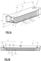
- FIGS. 1A and 1B are partial three-dimensional views of a print head 1 according to a first embodiment.
- the view of the Figure 1A results from a section of the print head 1 along a transverse plane and along a first longitudinal plane.
- the partial view of the Figure 1B results from a section of the print head 1 along a second longitudinal plane parallel to the first longitudinal plane.
- the print head 1 comprises a body 10 and a plurality of nozzles 11 located inside the body 10.
- the nozzles 11 are arranged in one or more rows.
- only one row of nozzles 11 is shown in the Figure 1A (the first longitudinal section plane passing through said row of nozzles).
- the number of nozzles 11 in each row may be between 2 and 500.
- the print head 1 is intended for applying a coating product to an object to be coated, for example a motor vehicle body. It preferably operates according to the drop-on-demand (or DOD) technology. Each nozzle 11 is then configured to deposit the coating product drop by drop. To do this, each nozzle 11 can be equipped with a valve that is controlled in opening or closing, respectively to allow or prevent the flow of the coating product through the nozzle 11.
- the valves of the nozzles 11 are for example pneumovannes each comprising a controllable membrane. Such a valve is pneumatically controlled (e.g. with compressed air).
- the valves of the nozzles 11 can also be solenoid type valves.
- the print head is a continuous jet print head, i.e. it has permanently open circuits.
- the nozzles 11 are then devoid of valves.
- the coating product example below is paint, but it can also be a primer, varnish, or a more viscous product such as glue or putty.
- FIG. 2 is a larger-scale sectional view of a portion A of the print head 1, the portion A being located around a nozzle 11 (cf. Fig.1A ). It will be described jointly with the Figures 1A and 1B .
- Each nozzle 11 comprises an outlet channel 111 and an ejection orifice 112.
- the outlet channel 111 opens outside the body 10 via the ejection orifice 112, into a paint ejection zone 2.
- Each nozzle 11 is thus associated with an ejection zone 2 which extends in the extension of the outlet channel 111 of the nozzle 11.
- the outlet channel 111 and the ejection orifice 112 of the nozzles 11 are arranged in the body 10 of the print head 1. More particularly, the ejection orifice 112 is arranged in an ejection face 100 of the body 10.
- the ejection orifice 112 has a diameter that can be between 100 ⁇ m and 500 ⁇ m, for example equal to 150 ⁇ m.
- the ejection face 100 partly delimits the ejection zones 2.
- the ejection axis z of each nozzle 11, defined as the axis of the ejection orifice 112, is preferably oriented perpendicular to the ejection face 100.
- the supply circuit 12 has the function of supplying the nozzles 11 with paint. It comprises a so-called supply inlet 121 and extends inside the body 10 from the supply inlet 121 to the nozzles 11.
- the supply inlet 121 is an inlet orifice through which the paint enters the print head 1.
- the supply circuit 12 may also comprise a so-called purge or recirculation outlet 122 (cf. Fig.1B ).
- the purge outlet 122 is an outlet through which paint can be discharged from the print head 1 (and conveyed to recovery and treatment collectors or to the supply tanks).
- the purge outlet 122 serves to purge the circuit supply circuit 12, for example when changing paint shade.
- the supply circuit 12 can also be primed, i.e. filled with paint before a printing phase, by circulating the paint from the supply inlet 121 to the purge outlet 122 (but not through the nozzles 11).
- the supply inlet 121 and the purge outlet 122 are arranged in an outer wall of the body
- the supply circuit 12 may further comprise a storage chamber 123 (of the paint) connected to the supply inlet 121 and a plurality of distribution channels 124 (of the paint) connecting the storage chamber 123 to the nozzles 11.
- the storage chamber 123 is further connected to the purge outlet 122. Two elements of the same fluid circuit (or two elements belonging to two different fluid circuits) are considered to be connected when they are in fluid communication.
- Each distribution channel 124 may connect the storage chamber 123 to one or more nozzles 11, for example two consecutive nozzles in the row.
- the number of distribution channels 124 is equal to the number of nozzles 11 and each distribution channel 124 serves a single nozzle 11.
- the storage chamber 123 and the distribution channels 124 are arranged in the body 10.
- the supply inlet 121 and the purge outlet 122 can open directly into the storage chamber 123 or be connected to the storage chamber 123 by conduits called inlet and outlet respectively.
- the maintenance circuit 13 extends inside the body 10 to the ejection zone 2 of at least some of the nozzles 11, preferably all of the nozzles 11. It is configured to convey the maintenance fluid to the ejection zone 2 of at least some of the nozzles 11 and/or to evacuate the maintenance fluid from the ejection zone 2 of at least some of the nozzles 11 (preferably all of the nozzles 11).
- the maintenance circuit 13 comprises several first internal channels 131, called maintenance channels. Each first internal channel 131 is associated with one or more nozzles 11. Each first internal channel 131 opens into the ejection zone 2 of the nozzle(s) associated with the first internal channel 131.
- the maintenance circuit 13 is advantageously configured so that the maintenance fluid can be brought into each ejection zone 2 or evacuated from each ejection zone 2 by at least a first internal channel 131. All the nozzles 11 of the print head 1 can thus be maintained.
- the number of first internal channels 131 is equal to the number of nozzles 11 and each first internal channel 131 opens into the ejection zone 2 of a single nozzle 11 (in other words, each first internal channel 131 is associated with a single nozzle 11). Maintenance is thus accomplished in the same way and with the best level of performance for all nozzles.
- the maintenance circuit 13 comprises a first storage chamber 132 for the maintenance fluid and a first inlet-outlet 133.
- An inlet-outlet here designates an inlet and/or outlet orifice for the maintenance fluid in the print head 1.
- the first inlet-outlet 133 can open directly into the first storage chamber 132 or be connected to the first storage chamber 132 by a conduit. It is arranged in an external wall of the body 10.
- the first storage chamber 132 (also called the first distribution chamber for the maintenance fluid) is connected to the ejection zones 2 by the first internal channels 131.
- the maintenance circuit 13 extends here from the first inlet-outlet 133 to the ejection zones 2 of the nozzles 11.
- Each first internal channel 131 extends through an internal wall separating the first storage chamber 132 and the ejection zones 2 of the nozzles 11. Each first internal channel 131 may further extend partially into the first storage chamber 132, as illustrated in FIG. Figure 1A .
- the operation of cleaning the nozzles 11 and at least part of the supply circuit 12 consists of removing paint residues located in the nozzles 11 (typically in the outlet channel 111 and the ejection orifice 112) and in the supply circuit 12.
- the cleaning fluid can be brought into the ejection zone 2 of the nozzles 11 thanks to the first internal channels 131 of the maintenance circuit 13, then be evacuated in passing through the nozzles 11 and the supply circuit 12 (cf. Fig.2 ). The cleaning fluid then flows through the nozzles 11 in the opposite direction to the flow direction of the paint, also called the normal flow direction. Conversely, the cleaning fluid can be brought into the ejection zone 2 by passing through the nozzles 11 via the supply circuit 12, then be discharged from the ejection zone 2 via the first internal channels 131 of the maintenance circuit 13. The cleaning fluid then flows through the nozzles 11 in the normal flow direction.
- the cleaning fluid can be a liquid (volatile or not), a gas (for example air) or a mixture of liquid and gas.
- the cleaning liquid advantageously comprises a solvent (in order to “dissolve” the dry paint residues), preferably the same as that used in the composition of the paint.
- Such an operation can be performed to unclog clogged nozzles 11 and restore optimal operation (in particular to guarantee repeatable drop trajectories). It can also be performed between two phases of printing the object, during a change of paint shade, or after a prolonged shutdown of the print head.
- the supply circuit 12 is advantageously purged prior to this operation.
- a wetting operation of the nozzles 11 consists in forming a film of non-volatile liquid at the ejection orifice 112 of the nozzles 11, in order to prevent the paint from drying during a prolonged stoppage of printing and from clogging the nozzles 11.
- the non-volatile liquid also called wetting liquid or stop liquid
- the wetting liquid can be brought to the ejection orifice 112 of the nozzles 11 by the supply circuit 12, then evacuated by the supply circuit 12 or by the first internal channels 131.
- the maintenance circuit 13 only carries one or more maintenance fluids (cleaning fluid and/or wetting liquid), unlike the supply circuit 12 which can receive paint and maintenance fluids.
- the maintenance fluid is sucked in to be evacuated from the ejection zone 2 of the nozzles 11.
- the vacuum is preferably between 0.1 bar and 0.8 bar, for example equal to 0.5 bar.
- the maintenance fluid is injected into the print head 1 under a pressure that may be between 0.1 bar and 1 bar.
- the pressure and vacuum values depend on the type of operation desired and the properties of the maintenance fluid. For example, for a cleaning operation, it is It is advantageous to circulate the fluid quickly in the ejection zone and therefore to have high pressure/vacuum values. For a nozzle wetting operation, the wetting liquid is slowly brought into the ejection zone in order to form the wet film which will seal the nozzle.
- the first storage chamber 132 is preferably arranged to ensure identical pressure/vacuum along the print head 1 and thus ensure identical operation for all the nozzles 11.
- a first internal channel 131 may be arranged so that the maintenance fluid flows in contact with the ejection face 100. The latter can thus be cleaned and freed from paint residues between the end of the first internal channel 131 and the ejection orifice 112 of the associated nozzle(s) 11.
- the first internal channel 131 preferably comprises a wall forming a flat surface with the ejection face 100, as illustrated. It is for example oriented parallel to the ejection face 100.
- the first internal channel 131 is inclined relative to the ejection face 100 in the direction of the ejection orifice 112 of the nozzle(s) associated with the first internal channel 131.
- the first internal channel 131 opens into the ejection zone 2 at a distance d from the z axis of the ejection orifice 112 which is advantageously less than or equal to 1 mm, for example equal to 0.25 mm.
- a small distance between the end of the first internal channel 131 and the ejection orifice 112 improves the cleaning or wetting of the ejection orifice (by limiting the dispersion of the fluid jet) and facilitates the suction of the maintenance fluid.
- the first internal channel 131 preferably has a section with characteristic dimensions less than or equal to 0.5 mm, preferably less than or equal to 0.25 mm. This section is for example round (diameter less than or equal to 0.5 mm) or rectangular (height and width less than or equal to 0.5 mm).
- the length of the first internal channel 131 may be between 0.5 mm and 10 mm. Such a length makes it possible to properly “guide” the maintenance fluid to the ejection zone 2.
- all the first internal channels 131 of the maintenance circuit 13 have the same configuration and the same dimensions. In other words, they are identical.
- the first internal channels 131 are advantageously arranged in a plate (or layer) 101 called the external maintenance plate and arranged on the ejection face 100.
- This external maintenance plate 101 is of very low thickness, for example between 0.1 mm and 1 mm, and therefore does not significantly increase the size of the print head 1.
- FIG. 3 is a three-dimensional partial view of a print head 1 according to a second embodiment. It results from a section of the print head 1 along a transverse plane.
- the print head 1 according to the second embodiment differs from the print head 1 according to the first embodiment ( Figs.1A-1B ) mainly in the arrangement of the maintenance circuit 13.
- the maintenance circuit 13 comprises, in addition to the first internal channels 131, second internal channels 135.
- Each second internal channel 135 is associated with a first internal channel 131 and opens into the ejection zone 2 of the nozzle(s) 11 associated with said first internal channel 131.
- the second internal channels 135 serve to convey the maintenance fluid to the ejection zones 2 or to evacuate the maintenance fluid from the ejection zones 2.
- the number of second internal channels 135 is equal to the number of nozzles 11 and each second internal channel 135 opens into the ejection zone 2 of a single nozzle 11 (in other words, each second internal channel 135 is associated with a single nozzle 11).
- the maintenance circuit 13 further comprises a second storage (or distribution) chamber 136 for the maintenance fluid and a second inlet-outlet 137 connected to the second storage chamber 136.
- the second inlet-outlet 137 may be arranged in an external wall of the body 10 and open directly into the second storage chamber 136 or be connected to the second storage chamber 136 by a conduit.
- the second storage chamber 136 is preferably arranged to guarantee an identical pressure/vacuum along the print head 1 and thus ensure identical operation for all the nozzles 11.
- the maintenance circuit 13 here extends from the first inlet-outlet 133 to the ejection zones 2 of the nozzles 11 and from the ejection zones 2 to the second inlet-outlet 137.
- the second internal channels 135 connect the second storage chamber 136 to the ejection zones 2 of the nozzles 11.
- Each second internal channel 135 extends through an internal wall separating the second storage chamber 136 and the ejection zones 2 of the nozzles 11.
- Each second internal channel 135 may further extend partially into the second storage chamber 136, as illustrated in FIG. figure 3 .
- FIG 4 is a larger-scale sectional view of a portion B of the print head 1, the portion B being located around a nozzle 11 (cf. Fig.3 ).
- This figure shows a preferred arrangement of a first internal channel 131 and an associated second internal channel 135.
- the second internal channel 135 is located opposite the associated first internal channel 131 relative to the ejection orifice 112 of the nozzle 11. It may be arranged such that the maintenance fluid flows in contact with the ejection face 100, as previously described in relation to the first internal channel 131 ( figure 2 ). In this configuration, the first internal channel 131 and the second internal channel 135 are advantageously oriented in the same direction.
- the second internal channel 135 may be inclined relative to the ejection face 100 towards the ejection orifice 112.
- the second internal channel 135 opens into the ejection zone 2 at a distance d' from the z axis of the ejection orifice 112 which is advantageously less than or equal to 1 mm, for example equal to 0.25 mm.
- the distance between the end of the second internal channel 135 and the z axis of the ejection orifice 112 is preferably equal to the distance d between the end of the first internal channel 131 and the z axis of the ejection orifice 112.
- the second internal channel 135 preferably has a section with characteristic dimensions less than or equal to 0.5 mm, preferably less than or equal to 0.25 mm. This section is for example round (diameter less than or equal to 0.5 mm) or rectangular (height and width less than or equal to 0.5 mm). The length of the second internal channel 135 may be between 0.5 mm and 10 mm.
- the first internal channel 131 and the second internal channel 135 may be arranged symmetrically with respect to the ejection orifice 112 of the nozzle 11.
- all the second internal channels 135 of the maintenance circuit 13 have the same configuration and the same dimensions. They are therefore identical.
- the second internal channels 135 are advantageously arranged in the same external maintenance plate 101 as the first internal channels 131.
- the second internal channels 135 can perform the same function as the first internal channels 131 (i.e. suction or injection of the maintenance fluid). For example, they can be used to evacuate the maintenance fluid from the ejection zones 2 after it has circulated in the supply circuit 12 and the nozzles 11. Alternatively, the second internal channels 135 can perform a different function from that of the first internal channels 131. For example, they can be used to suck up the wetting liquid while the first internal channels 131 have served to bring it to the ejection zones 2.
- the operation of cleaning the ejection face 100 and the ejection orifice of the nozzles 11 comprises the routing of the cleaning fluid to the ejection zones 2 by the first internal channels 131 and the evacuation of the cleaning fluid by the second internal channels 135, or vice versa.
- the cleaning fluid circulates only in the maintenance circuit 13 (between the first and second inlet-outlets 133, 137) and in the ejection zones 2, in contact with the ejection face 100.
- first internal channel 131 and the second internal channel 135 are located on either side of the ejection zone 2 (and preferably located opposite each other), a more thorough cleaning of the ejection face 100 can be obtained.
- the print head 1 according to the second embodiment thus allows an additional maintenance operation to be carried out.
- the pressure and vacuum values are similar to those indicated previously. Implementation is easier because maintenance is completely unrelated to the power supply (removal of valves in the circuit).
- the maintenance circuit 13 comprises a single first internal channel 121 opening into the ejection zone 2 of several nozzles 11, and preferably of all the nozzles 11.
- a maintenance circuit 13 comprising several first internal channels 131, however, has better performance (in terms of cleaning the nozzles for example) than a maintenance circuit 1 with a single first internal channel common to several nozzles. Indeed, the maintenance fluid can thus be conveyed to the ejection zone 2 of the nozzles or evacuated from the ejection zone 2 of the nozzles more precisely. Multiplying the number of first internal channels 131 also makes it possible to reduce their size and therefore to increase the speed of the maintenance fluid which circulates inside.
- the maintenance circuit 13 may comprise (in addition to the first internal channel(s) 131) only one second internal channel 135 opening into the ejection zone 2 of several nozzles 11, and preferably of all the nozzles 11.
- FIG. 5 represents a third embodiment, in which the maintenance circuit 13 of the print head is devoid of first internal channels 131 and second channels 135.
- the first storage chamber 132 communicates with the ejection zone 2 of at least part of the nozzles 11 by one or more first openings 138.
- the first storage chamber 132 communicates with the ejection zone 2 of each of the nozzles 11 by a single first opening 138.
- the number of first openings 138 is then equal to the number of nozzles 11.
- the first openings 138 are arranged in the wall of the body 10 which separates the first storage chamber 132 and the ejection zones 2. They result from the intersection between the first storage chamber 132 and the ejection zones 2 (here in the form of straight cylinders, in the extension of the outlet channels 111 of the nozzles 11).
- the second storage chamber 136 communicates with the ejection zone 2 of at least part of the nozzles 11 via one or more second openings 139.
- the second storage chamber 136 communicates with the ejection zone 2 of each of the nozzles 11 via a single second opening 139.
- the number of second openings 139 is then equal to the number of nozzles 11.
- the second openings 139 are arranged in the wall of the body 10 which separates the second storage chamber 136 and the ejection zones 2. They result from the intersection between the second storage chamber 136 and the ejection zones 2.
- a nozzle 11 and a first opening 138 may be associated with each second opening 139.
- Each second opening 139 is advantageously located opposite the associated first opening 138 relative to the ejection orifice 112 of the associated nozzle 11.
- the first opening 138, the second opening 139 and the end of the ejection orifice 112 are aligned. This arrangement improves the cleaning and wetting of the ejection orifice 111 of the nozzle 11.
- the first and second openings 138-139 are advantageously arranged so that the maintenance fluid flows in contact with the ejection face 100.
- the first and second openings 138-139 can be likened to (first and second) internal channels of zero length.
- Print head 1 of the figure 5 works the same way as the print head of the figure 3 , the other elements, not mentioned, being otherwise identical.
- the maintenance circuit is devoid of a second storage chamber 136.
- the print head then operates in the same way as the print head 1 of the Figures 1A-1B .
- the print head comprises only one nozzle 11, a first internal channel 131 opening into the ejection zone 2 of the nozzle 11 (as described in relation to the figure 2 ) or a first opening 138 and, advantageously, a second internal channel 132 opening into the ejection zone 2 of the nozzle 11 (as described in relation to the figure 4 ) or a second opening 139.
- the supply circuit 12 then comprises only one distribution channel 124 connecting the storage chamber 123 to the nozzle 11.
- FIG. 6 shows a fluid diagram of a coating installation 3 according to a first embodiment, comprising the print head 1 of the Figures 1A-1B (or the variant of the third embodiment).
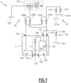
- FIG 7 shows a fluid diagram of a coating installation 3 according to a second embodiment, comprising the print head 1 of the figure 3 (or of the figure 5 ).
- the coating product supply circuit 33 may comprise at least one coating product reservoir 331 and at least one so-called filling valve 332 connected on the one hand to the coating product reservoir 331 and on the other hand to the supply inlet 121 of the supply circuit 12.
- the injection circuit 31 (also called the maintenance fluid supply circuit) comprises at least one pressurized tank 311 containing maintenance fluid and at least one so-called injection valve 312 connected on the one hand to the pressurized tank 311 and on the other hand to the inlet of the print head 1.
- pressurized is meant that the pressure inside the tank is higher than atmospheric pressure.
- the injection circuit 31 may also comprise means for adjusting the maintenance fluid pressure. These adjustment means may be arranged between the pressurized tank 311 and the injection valve 312. They comprise for example a variable flow valve 313. Alternatively, the pressure adjustment may be carried out at the pressurized tank 311 or even further upstream (compressed air source, pump, etc.).
- the injection circuit 31 then advantageously comprises a two-way valve 313 arranged between the pressurized tank 311 and the injection valve 312.
- the maintenance fluid pressure adjustment means may then comprise a variable flow valve 313 coupled to each of the first and second pressurized tanks 311a-311b.
- the first and second injection valves 312a-312b are preferably two-way valves (pneumatic valve, solenoid type, etc.).
- the suction circuit 32 comprises a vacuum generator 321 (venturi effect system or vacuum pump) and at least one valve 322 called a suction valve connected on the one hand to the vacuum generator 321 and on the other hand to the outlet of the print head 1.
- the suction circuit 32 advantageously comprises a recovery volume 323, connected to the vacuum generator 321 and intended to recover the suctioned maintenance fluid.
- the first and second suction valves 322a-322b are preferably two-way valves (pneumovanne type, solenoid, etc.).
- the vacuum generator 321 may be a venturi effect system comprising an ejector, a compressed air buffer volume, a pressure gauge and means for adjusting the depression generated by the vacuum generator 321.
- the vacuum generator 321 may comprise a vacuum pump arranged above the recovery volume 323.
- the first injection valve 312a is connected to the first inlet-outlet 133 of the maintenance circuit 13 and the second injection valve 312b is connected to the supply inlet 121 of the supply circuit 12 (or to the purge outlet 122 of the supply circuit 12, not shown in the figure 6 ).
- first suction valve 322a is connected to the first inlet-outlet 133 of the maintenance circuit 13 and the second suction valve 322b is connected to the supply inlet 121 of the supply circuit 12 (or to the purge outlet 122 of the supply circuit 12, not shown in the drawing). figure 6 ).
- the first output of the print head 1 and the second input of the print head 1 are merged with the first input-output 133 of the maintenance circuit 13.
- the second output of the print head 1 and the first input of the print head 1 are merged with the supply input 121 of the supply circuit 12.
- the first injection valve 312a is connected to the first inlet-outlet 133 of the maintenance circuit 13 and the second injection valve 312b is connected to the second inlet-outlet 137 of the maintenance circuit 13.
- first suction valve 322a is connected to the first inlet-outlet 133 of the maintenance circuit 13 and the second suction valve 322b is connected to the second inlet-outlet 137 of the maintenance circuit 13.
- the first output of the print head 1 and the second input of the print head 1 are merged with the first input-output 133 of the maintenance circuit 13.
- the second output of the print head 1 and the first input of the print head 1 are merged with the second input-output 137 of the maintenance circuit 13.
- the two injection valves 312a-312b and the two suction valves 322a-322b allow the multitude of maintenance operations described above to be carried out.
- the first injection valve 312a and the first suction valve 322a are advantageously controlled in phase opposition. In other words, when one is open, the other is closed, and vice versa.
- the second injection valve 312b and the second suction valve 322b are also advantageously controlled in phase opposition.
- the first injection valve 312a is opened only when the second suction valve 322b is open and the second injection valve 312b is opened only when the first suction valve 322a is open.
- the injection of the maintenance fluid always takes place at the same time as the suction.
- the first suction valve 322a (respectively the second suction valve 322b) is permanently open (continuous suction) and the second injection valve 312b (respectively the first injection valve 312a) is intermittently open, so as to produce pulsations of cleaning fluid.
- the two injection valves 312a-312b and the two suction valves 322a-322b allow the cleaning fluid to be circulated in both directions inside the print head 1, thereby improving the cleaning operations.
- the cleaning fluid may first be injected through the first inlet-outlet 133 and sucked through the supply inlet 121, then injected through the supply inlet 121 and sucked through the first inlet-outlet 133 (or in the reverse order).
- the coating installation 3 of the figure 7 further comprises a third suction valve connected on the one hand to the vacuum generator 321 and on the other hand to the supply inlet 121, as well as a third injection valve connected on the one hand to the first and second pressurized tanks 311a-311b and on the other hand to the supply inlet 121.
- This variant embodiment makes it possible to clean (in the two directions) the nozzles 11 and at least part of the supply circuit 12. For example, the cleaning fluid can be injected through the supply inlet 121 and be sucked through the first inlet-outlet 133 and the second inlet-outlet 137 (or vice versa).
- the body 10 of the print head 1 (containing the nozzles 11, the power supply circuit 12 and the maintenance circuit 13) can be manufactured in different ways. Examples include diffusion welding or brazing of metal sheets, selective laser sintering of metal powder, micro-molding and silicon microelectromechanical systems (MEMS) manufacturing techniques.
- MEMS microelectromechanical systems
- the body can also be composed of machined elements assembled by gluing or screwing, a seal can be installed between the different components to ensure sealing.
- the plates are preferably made of metal, for example stainless steel. They are machined to form the different parts of the nozzles 11, the supply circuit 12 and the maintenance circuit 13, for example by chemical cutting, laser cutting or sinking electroerosion (also called EDM, for “electrical discharge machining” in English).
- the plates also called “strata”) preferably have a thickness of between 10 ⁇ m and 1000 ⁇ m.
- Annealing is preferably carried out at a temperature between 0.6.T f and 0.8.T f , where T f is the melting temperature of the metal.
- the annealing time may be between 1 h and 3 h.
- the surfaces of the plates which are brought into contact preferably have a low surface roughness, typically less than 0.5 ⁇ m. This roughness value is expressed as a root mean square value.
- the body 10 obtained is robust, because it is ultimately formed from a single piece (it has a monolithic appearance).
- the diffusion welding technique is also advantageous in that it does not require additional material (glue, filler metal, etc.) at the interfaces between the metal plates.
- the membranes of the pneumovannes belonging to the nozzles 11 are advantageously formed after manufacture of the body 10.
Landscapes
- Engineering & Computer Science (AREA)
- Manufacturing & Machinery (AREA)
- Ink Jet (AREA)
- Coating Apparatus (AREA)
- Particle Formation And Scattering Control In Inkjet Printers (AREA)
Claims (15)
- Druckkopf (1) zum Aufbringen eines Beschichtungsprodukts auf einen zu beschichtenden Gegenstand, der Druckkopf umfassend einen Körper (10), in dem Folgendes angeordnet ist:- mehrere Düsen (11), jeweils umfassend eine Ausstoßöffnung (112) und einen Austrittskanal (111), der in eine Ausstoßzone (2) des Beschichtungsprodukts durch die Ausstoßöffnung (112) mündet;- einen mit der Düse (11) verbundenen Zufuhrkreislauf (12) für Beschichtungsmaterial;der Druckkopf ferner umfassend einen Wartungskreislauf (13), der dazu dient, ein Wartungsfluids zu leiten, wobei sich der Wartungskreislauf (13) innerhalb des Körpers (10) bis zu dem Ausstoßbereich (2) der Düse (11) erstreckt und umfassend einen ersten inneren Kanal (131; 138), der in den Ausstoßbereich (2) mindestens einer Düse (11) mündet,dadurch gekennzeichnet, dass der Wartungskreislauf (13) eine Vielzahl von ersten inneren Kanälen (131; 138) umfasst, wobei jeder erste innere Kanal (131; 138) in den Ausstoßbereich (2) einer einzelnen Düse (11) mündet, die mit dem ersten inneren Kanal (131; 138) assoziiert ist, wobei die Anzahl der ersten inneren Kanäle (131; 138) gleich wie die Anzahl der Düsen (11) ist.
- Druckkopf (1) nach Anspruch 1, wobei der Wartungskreislauf (13) eine Vielzahl von zweiten inneren Kanälen (135) umfasst, wobei jeder zweite innere Kanal (135) mit einem ersten inneren Kanal (131) assoziiert ist und in den Ausstoßbereich (2) der einzigen Düse (11) mündet, die mit dem ersten inneren Kanal (131) assoziiert ist.
- Druckkopf (1) nach Anspruch 2, wobei sich jeder zweite innere Kanal (135) gegenüber dem assoziierten ersten inneren Kanal (131) in Bezug auf die Ausstoßöffnung (112) der Düse (11) in dem Ausstoßbereich befindet, in den dieser zweite Kanal (135) mündet.
- Druckkopf (1) nach einem der Ansprüche 2 und 3, wobei jeder erste innere Kanal (131) und der assoziierte zweite innere Kanal (135) in eine gleiche Richtung ausgerichtet sind.
- Druckkopf (1) nach einem der Ansprüche 1 bis 4, umfassend eine Ausstoßseite (100), in der die Ausstoßöffnung (112) der Düse (11) ausgebildet ist und in der der erste innere Kanal (131) angeordnet ist, sodass das Wartungsfluid in Kontakt mit der Ausstoßfläche (100) strömt.
- Druckkopf (1) nach einem der Ansprüche 1 bis 4, umfassend einer Ausstoßseite (100), in der die Ausstoßöffnung (112) der Düse (11) ausgebildet ist und in der der erste innere Kanal (131) in einer Platte (101) angeordnet ist, die auf der Ausstoßseite (100) des Druckkopfs (1) angeordnet ist.
- Druckkopf (1) nach einem der Ansprüche 1 bis 6, wobei der erste innere Kanal (131) ein Ende aufweist, das zum Ausstoßbereich (2) hin offen ist und sich in einem Abstand (d) von weniger als oder gleich wie 1 mm von der Ausstoßöffnung (112) der Düse (11) befindet.
- Druckkopf (1) nach einem der Ansprüche 1 bis 7, wobei der Wartungskreislauf (13) eine erste Speicherkammer (132) für das Wartungsfluid umfasst, wobei die erste Speicherkammer (132) über einen der ersten inneren Kanäle (131), dessen Länge zwischen 0,5 mm und 10 mm liegt, mit dem Ausstoßbereich (2) jeder Düse (11) in Verbindung ist.
- Druckkopf (1) nach einem der Ansprüche 1 bis 7, wobei der Wartungskreislauf (13) eine erste Speicherkammer (132) für das Wartungsfluid umfasst, wobei die erste Speicherkammer (132) über eine erste Öffnung (138) mit den Ausstoßbereichen (2) jeder Düse in Verbindung ist.
- Druckkopf (1) nach einem der Ansprüche 8 oder 9, wobei sich die ersten inneren Kanäle (131) oder die ersten Öffnungen (138) durch eine Innenwand des Körpers (10) erstrecken, die die erste Speicherkammer (132) und die Ausstoßbereiche (2) der Düsen (11) voneinander trennt.
- Druckkopf (1) nach einem der Ansprüche 1 bis 10, wobei die ersten inneren Kanäle (131) in einer externen Wartungsplatte (101) ausgebildet sind, die auf einer Ausstoßseite (100) des Körpers (10) angeordnet ist, in der die Ausstoßöffnungen (112) der Düsen (11) ausgebildet sind.
- Druckkopf (1) nach einem der Ansprüche 1 bis 11, wobei die ersten inneren Kanäle (131) einen Querschnitt mit charakteristischen Abmessungen von weniger als oder gleich wie 0,5 mm, vorzugsweise weniger als oder gleich wie 0,25 mm, aufweisen.
- Beschichtungsanlage (3), umfassend:- einen Druckkopf (1) nach einem der Ansprüche 1 bis 12;- einen Injektionskreislauf (31) für das Wartungsfluid, der mit mindestens einem Eingang des Druckkopfs (1) verbunden ist;- einen Saugkreislauf (32) für das Wartungsfluid, der mit mindestens einem Auslass des Druckkopfs (1) verbunden ist.
- Beschichtungsanlage (3) nach Anspruch 13, wobei der Saugkreislauf (32) Folgendes umfasst:- einen Vakuumerzeuger (321);- ein erstes Saugventil (322a), das einerseits mit dem Vakuumerzeuger (321) und andererseits mit einem ersten Ausgang des Druckkopfs (1) verbunden ist; und- ein zweites Saugventil (322b), das einerseits mit dem Vakuumerzeuger (321) und andererseits mit einem zweiten Ausgang des Druckkopfs (1) verbunden ist.
- Beschichtungsanlage (3) nach einem der Ansprüche 13 und 14, wobei der Injektionskreislauf (33) Folgendes umfasst:- einen ersten Druckbehälter (311a), der ein Reinigungsfluid enthält;- einen zweiten Druckbehälter (311b), der eine Befeuchtungsflüssigkeit enthält;- ein erstes Injektionsventil (312a), das einerseits mit dem ersten und dem zweiten Druckbehälter (311a-311b) und andererseits mit einem ersten Eingang des Druckkopfs (1) verbunden ist;- ein zweites Injektionsventil (312b), das einerseits mit dem ersten und dem zweiten Druckbehälter (311a-311b) und andererseits mit einem zweiten Eingang des Druckkopfs (1) verbunden ist.
Applications Claiming Priority (1)
| Application Number | Priority Date | Filing Date | Title |
|---|---|---|---|
| FR2203285A FR3134341B1 (fr) | 2022-04-11 | 2022-04-11 | Tête d’impression comprenant un circuit de maintenance et installation de revêtement |
Publications (3)
| Publication Number | Publication Date |
|---|---|
| EP4261042A1 EP4261042A1 (de) | 2023-10-18 |
| EP4261042C0 EP4261042C0 (de) | 2025-03-05 |
| EP4261042B1 true EP4261042B1 (de) | 2025-03-05 |
Family
ID=81851188
Family Applications (1)
| Application Number | Title | Priority Date | Filing Date |
|---|---|---|---|
| EP23167201.5A Active EP4261042B1 (de) | 2022-04-11 | 2023-04-07 | Druckkopf mit wartungsschaltung und beschichtungsanlage |
Country Status (7)
| Country | Link |
|---|---|
| US (1) | US12370801B2 (de) |
| EP (1) | EP4261042B1 (de) |
| JP (1) | JP2023155899A (de) |
| KR (1) | KR20230145916A (de) |
| CN (1) | CN116890534A (de) |
| ES (1) | ES3029958T3 (de) |
| FR (1) | FR3134341B1 (de) |
Family Cites Families (5)
| Publication number | Priority date | Publication date | Assignee | Title |
|---|---|---|---|---|
| US5877788A (en) * | 1995-05-09 | 1999-03-02 | Moore Business Forms, Inc. | Cleaning fluid apparatus and method for continuous printing ink-jet nozzle |
| US6273103B1 (en) * | 1998-12-14 | 2001-08-14 | Scitex Digital Printing, Inc. | Printhead flush and cleaning system and method |
| US8876252B2 (en) * | 2011-05-02 | 2014-11-04 | Illinois Tool Works, Inc. | Solvent flushing for fluid jet device |
| US10987932B2 (en) * | 2017-03-03 | 2021-04-27 | Kyocera Document Solutions Inc. | Recording head recovery method |
| FR3094899B1 (fr) | 2019-04-15 | 2022-10-07 | Exel Ind | Installation d’application de produit de revêtement et procédé de nettoyage d’une telle installation |
-
2022
- 2022-04-11 FR FR2203285A patent/FR3134341B1/fr active Active
-
2023
- 2023-04-03 KR KR1020230043781A patent/KR20230145916A/ko active Pending
- 2023-04-03 US US18/295,256 patent/US12370801B2/en active Active
- 2023-04-05 JP JP2023061362A patent/JP2023155899A/ja active Pending
- 2023-04-07 EP EP23167201.5A patent/EP4261042B1/de active Active
- 2023-04-07 ES ES23167201T patent/ES3029958T3/es active Active
- 2023-04-10 CN CN202310371818.3A patent/CN116890534A/zh active Pending
Also Published As
| Publication number | Publication date |
|---|---|
| JP2023155899A (ja) | 2023-10-23 |
| CN116890534A (zh) | 2023-10-17 |
| US20230321984A1 (en) | 2023-10-12 |
| FR3134341A1 (fr) | 2023-10-13 |
| EP4261042C0 (de) | 2025-03-05 |
| US12370801B2 (en) | 2025-07-29 |
| FR3134341B1 (fr) | 2024-04-19 |
| KR20230145916A (ko) | 2023-10-18 |
| ES3029958T3 (en) | 2025-06-26 |
| EP4261042A1 (de) | 2023-10-18 |
Similar Documents
| Publication | Publication Date | Title |
|---|---|---|
| EP3725421B1 (de) | Anlage zum auftragen eines beschichtungsmittels und reinigungsverfahren einer solchen anlage | |
| EP1303359B1 (de) | Verfahren und station zum wechseln von flüssigkeit für eine spritzanlage | |
| EP0090691B1 (de) | Strahldüse deren Strahl flache und feste Schleifteilchen aufweist | |
| EP1616648B1 (de) | Bohrvorrichtung und Bohrverfahren in dem eine derartige Vorrichtung eingesetzt wird | |
| EP1221358B1 (de) | Düse zum konzentrierten Sprühen eines mit Feststoffteilchen geladenen Mediums, besonders zum feinen und präzisen Reinigen und zur Kontrolle von Oberflächen | |
| FR2857281A1 (fr) | Changeur de couleurs de peinture en poudre | |
| EP0802827A1 (de) | Zerstäubungsdüse | |
| FR3082779A1 (fr) | Procede et dispositif de maintenance d'une tete d'impression par buse | |
| EP4261042B1 (de) | Druckkopf mit wartungsschaltung und beschichtungsanlage | |
| FR2939056A1 (fr) | Projecteur de produit de revetement | |
| WO2015022328A1 (fr) | Pulverisateur d'un produit de revetement liquide et installation de pulverisation comprenant un tel pulverisateur | |
| FR2692940A1 (fr) | Dispositif de recyclage de gaz d'échappement et procédé pour sa fabrication. | |
| FR2810301A1 (fr) | Dispositif de reprise d'air statique pour distributeur de produit liquide | |
| FR2727648A1 (fr) | Procede de fabrication micromecanique de buses pour jets de liquide | |
| FR2747960A1 (fr) | Dispositif a buse(s) pour imprimante a jet d'encre protege(s) de la pollution par un traitement de non-mouillabilite et procede de fabritcation | |
| EP1883478B1 (de) | Düse mit einer wirbelkammer | |
| EP0715069B1 (de) | Brennstoffdispersionblende für Einspritzdüse einer Einspritzbrennkraftmaschine | |
| FR3082778A1 (fr) | Tete d'impression d'une imprimante a jet d'encre avec 2 gouttieres de recuperation, dont une mobile | |
| EP3959063A1 (de) | Extrusionskopf für generative fertigung, system für generative fertigung und verfahren | |
| LU86119A1 (fr) | Dispositif de depot electrolytique et procede pour sa mise en oeuvre | |
| BE1006193A3 (fr) | Injecteur et installation equipee d'un tel injecteur. | |
| FR3162010A1 (fr) | Cartouche pour module d’injection, module d’injection de produit multi-composant comprenant une telle cartouche et pulvérisateur de produit de revêtement comprenant un tel module | |
| WO2025238324A1 (fr) | Procede de depoudrage d'une piece obtenue par fabrication additive et dispositif de mise en oeuvre | |
| FR2896708A1 (fr) | Dispositif de preparation de surfaces par injection extraction d'un fluide | |
| FR2963575A1 (fr) | Dispositif d'ejection de liquide sous forme de microgouttes |
Legal Events
| Date | Code | Title | Description |
|---|---|---|---|
| PUAI | Public reference made under article 153(3) epc to a published international application that has entered the european phase |
Free format text: ORIGINAL CODE: 0009012 |
|
| STAA | Information on the status of an ep patent application or granted ep patent |
Free format text: STATUS: THE APPLICATION HAS BEEN PUBLISHED |
|
| AK | Designated contracting states |
Kind code of ref document: A1 Designated state(s): AL AT BE BG CH CY CZ DE DK EE ES FI FR GB GR HR HU IE IS IT LI LT LU LV MC ME MK MT NL NO PL PT RO RS SE SI SK SM TR |
|
| STAA | Information on the status of an ep patent application or granted ep patent |
Free format text: STATUS: REQUEST FOR EXAMINATION WAS MADE |
|
| 17P | Request for examination filed |
Effective date: 20240320 |
|
| RBV | Designated contracting states (corrected) |
Designated state(s): AL AT BE BG CH CY CZ DE DK EE ES FI FR GB GR HR HU IE IS IT LI LT LU LV MC ME MK MT NL NO PL PT RO RS SE SI SK SM TR |
|
| GRAP | Despatch of communication of intention to grant a patent |
Free format text: ORIGINAL CODE: EPIDOSNIGR1 |
|
| STAA | Information on the status of an ep patent application or granted ep patent |
Free format text: STATUS: GRANT OF PATENT IS INTENDED |
|
| INTG | Intention to grant announced |
Effective date: 20241127 |
|
| GRAS | Grant fee paid |
Free format text: ORIGINAL CODE: EPIDOSNIGR3 |
|
| GRAA | (expected) grant |
Free format text: ORIGINAL CODE: 0009210 |
|
| STAA | Information on the status of an ep patent application or granted ep patent |
Free format text: STATUS: THE PATENT HAS BEEN GRANTED |
|
| AK | Designated contracting states |
Kind code of ref document: B1 Designated state(s): AL AT BE BG CH CY CZ DE DK EE ES FI FR GB GR HR HU IE IS IT LI LT LU LV MC ME MK MT NL NO PL PT RO RS SE SI SK SM TR |
|
| REG | Reference to a national code |
Ref country code: GB Ref legal event code: FG4D Free format text: NOT ENGLISH |
|
| REG | Reference to a national code |
Ref country code: CH Ref legal event code: EP |
|
| REG | Reference to a national code |
Ref country code: IE Ref legal event code: FG4D Free format text: LANGUAGE OF EP DOCUMENT: FRENCH |
|
| REG | Reference to a national code |
Ref country code: DE Ref legal event code: R096 Ref document number: 602023002269 Country of ref document: DE |
|
| U01 | Request for unitary effect filed |
Effective date: 20250311 |
|
| U07 | Unitary effect registered |
Designated state(s): AT BE BG DE DK EE FI FR IT LT LU LV MT NL PT RO SE SI Effective date: 20250318 |
|
| U20 | Renewal fee for the european patent with unitary effect paid |
Year of fee payment: 3 Effective date: 20250325 |
|
| REG | Reference to a national code |
Ref country code: ES Ref legal event code: FG2A Ref document number: 3029958 Country of ref document: ES Kind code of ref document: T3 Effective date: 20250626 |
|
| PG25 | Lapsed in a contracting state [announced via postgrant information from national office to epo] |
Ref country code: RS Free format text: LAPSE BECAUSE OF FAILURE TO SUBMIT A TRANSLATION OF THE DESCRIPTION OR TO PAY THE FEE WITHIN THE PRESCRIBED TIME-LIMIT Effective date: 20250605 |
|
| PGFP | Annual fee paid to national office [announced via postgrant information from national office to epo] |
Ref country code: ES Payment date: 20250512 Year of fee payment: 3 |
|
| PG25 | Lapsed in a contracting state [announced via postgrant information from national office to epo] |
Ref country code: NO Free format text: LAPSE BECAUSE OF FAILURE TO SUBMIT A TRANSLATION OF THE DESCRIPTION OR TO PAY THE FEE WITHIN THE PRESCRIBED TIME-LIMIT Effective date: 20250605 |
|
| PG25 | Lapsed in a contracting state [announced via postgrant information from national office to epo] |
Ref country code: HR Free format text: LAPSE BECAUSE OF FAILURE TO SUBMIT A TRANSLATION OF THE DESCRIPTION OR TO PAY THE FEE WITHIN THE PRESCRIBED TIME-LIMIT Effective date: 20250305 |
|
| PG25 | Lapsed in a contracting state [announced via postgrant information from national office to epo] |
Ref country code: GR Free format text: LAPSE BECAUSE OF FAILURE TO SUBMIT A TRANSLATION OF THE DESCRIPTION OR TO PAY THE FEE WITHIN THE PRESCRIBED TIME-LIMIT Effective date: 20250606 |
|
| PGFP | Annual fee paid to national office [announced via postgrant information from national office to epo] |
Ref country code: TR Payment date: 20250505 Year of fee payment: 3 |
|
| PG25 | Lapsed in a contracting state [announced via postgrant information from national office to epo] |
Ref country code: SM Free format text: LAPSE BECAUSE OF FAILURE TO SUBMIT A TRANSLATION OF THE DESCRIPTION OR TO PAY THE FEE WITHIN THE PRESCRIBED TIME-LIMIT Effective date: 20250305 |
|
| PG25 | Lapsed in a contracting state [announced via postgrant information from national office to epo] |
Ref country code: PL Free format text: LAPSE BECAUSE OF FAILURE TO SUBMIT A TRANSLATION OF THE DESCRIPTION OR TO PAY THE FEE WITHIN THE PRESCRIBED TIME-LIMIT Effective date: 20250305 |
|
| PG25 | Lapsed in a contracting state [announced via postgrant information from national office to epo] |
Ref country code: CZ Free format text: LAPSE BECAUSE OF FAILURE TO SUBMIT A TRANSLATION OF THE DESCRIPTION OR TO PAY THE FEE WITHIN THE PRESCRIBED TIME-LIMIT Effective date: 20250305 |
|
| PG25 | Lapsed in a contracting state [announced via postgrant information from national office to epo] |
Ref country code: SK Free format text: LAPSE BECAUSE OF FAILURE TO SUBMIT A TRANSLATION OF THE DESCRIPTION OR TO PAY THE FEE WITHIN THE PRESCRIBED TIME-LIMIT Effective date: 20250305 |
|
| PG25 | Lapsed in a contracting state [announced via postgrant information from national office to epo] |
Ref country code: IS Free format text: LAPSE BECAUSE OF FAILURE TO SUBMIT A TRANSLATION OF THE DESCRIPTION OR TO PAY THE FEE WITHIN THE PRESCRIBED TIME-LIMIT Effective date: 20250705 |
|
| PG25 | Lapsed in a contracting state [announced via postgrant information from national office to epo] |
Ref country code: MC Free format text: LAPSE BECAUSE OF FAILURE TO SUBMIT A TRANSLATION OF THE DESCRIPTION OR TO PAY THE FEE WITHIN THE PRESCRIBED TIME-LIMIT Effective date: 20250305 |
|
| REG | Reference to a national code |
Ref country code: CH Ref legal event code: R18 Free format text: ST27 STATUS EVENT CODE: U-0-0-R10-R18 (AS PROVIDED BY THE NATIONAL OFFICE) Effective date: 20260106 |
|
| PLBE | No opposition filed within time limit |
Free format text: ORIGINAL CODE: 0009261 |
|
| STAA | Information on the status of an ep patent application or granted ep patent |
Free format text: STATUS: NO OPPOSITION FILED WITHIN TIME LIMIT |
|
| REG | Reference to a national code |
Ref country code: CH Ref legal event code: L10 Free format text: ST27 STATUS EVENT CODE: U-0-0-L10-L00 (AS PROVIDED BY THE NATIONAL OFFICE) Effective date: 20260114 |
|
| 26N | No opposition filed |
Effective date: 20251208 |
|
| PG25 | Lapsed in a contracting state [announced via postgrant information from national office to epo] |
Ref country code: IE Free format text: LAPSE BECAUSE OF NON-PAYMENT OF DUE FEES Effective date: 20250407 |