EP0090739A1 - Elektromagnetische Einspritzanlage für Dieselmotoren die einen Einspritzverlauf der "Druck-Zeit"-Type erzeugt - Google Patents
Elektromagnetische Einspritzanlage für Dieselmotoren die einen Einspritzverlauf der "Druck-Zeit"-Type erzeugt Download PDFInfo
- Publication number
- EP0090739A1 EP0090739A1 EP83400646A EP83400646A EP0090739A1 EP 0090739 A1 EP0090739 A1 EP 0090739A1 EP 83400646 A EP83400646 A EP 83400646A EP 83400646 A EP83400646 A EP 83400646A EP 0090739 A1 EP0090739 A1 EP 0090739A1
- Authority
- EP
- European Patent Office
- Prior art keywords
- pressure
- solenoid valve
- injection
- injector
- time
- Prior art date
- Legal status (The legal status is an assumption and is not a legal conclusion. Google has not performed a legal analysis and makes no representation as to the accuracy of the status listed.)
- Granted
Links
- 238000002347 injection Methods 0.000 title claims abstract description 46
- 239000007924 injection Substances 0.000 title claims abstract description 46
- 239000000446 fuel Substances 0.000 claims abstract description 6
- 230000001105 regulatory effect Effects 0.000 claims abstract description 3
- 230000000694 effects Effects 0.000 claims abstract 2
- 238000011144 upstream manufacturing Methods 0.000 claims description 3
- 239000000243 solution Substances 0.000 description 6
- 238000010586 diagram Methods 0.000 description 4
- 239000002283 diesel fuel Substances 0.000 description 2
- 238000006073 displacement reaction Methods 0.000 description 2
- 206010013647 Drowning Diseases 0.000 description 1
- 230000006978 adaptation Effects 0.000 description 1
- 230000003042 antagnostic effect Effects 0.000 description 1
- 230000000712 assembly Effects 0.000 description 1
- 238000000429 assembly Methods 0.000 description 1
- 238000002485 combustion reaction Methods 0.000 description 1
- 230000008602 contraction Effects 0.000 description 1
- 230000001934 delay Effects 0.000 description 1
- 238000005516 engineering process Methods 0.000 description 1
- 238000004519 manufacturing process Methods 0.000 description 1
- 230000010363 phase shift Effects 0.000 description 1
- 230000000284 resting effect Effects 0.000 description 1
- 230000000717 retained effect Effects 0.000 description 1
- 238000004513 sizing Methods 0.000 description 1
- 239000007921 spray Substances 0.000 description 1
Images

Classifications
-
- F—MECHANICAL ENGINEERING; LIGHTING; HEATING; WEAPONS; BLASTING
- F02—COMBUSTION ENGINES; HOT-GAS OR COMBUSTION-PRODUCT ENGINE PLANTS
- F02M—SUPPLYING COMBUSTION ENGINES IN GENERAL WITH COMBUSTIBLE MIXTURES OR CONSTITUENTS THEREOF
- F02M63/00—Other fuel-injection apparatus having pertinent characteristics not provided for in groups F02M39/00 - F02M57/00 or F02M67/00; Details, component parts, or accessories of fuel-injection apparatus, not provided for in, or of interest apart from, the apparatus of groups F02M39/00 - F02M61/00 or F02M67/00; Combination of fuel pump with other devices, e.g. lubricating oil pump
- F02M63/02—Fuel-injection apparatus having several injectors fed by a common pumping element, or having several pumping elements feeding a common injector; Fuel-injection apparatus having provisions for cutting-out pumps, pumping elements, or injectors; Fuel-injection apparatus having provisions for variably interconnecting pumping elements and injectors alternatively
- F02M63/0205—Fuel-injection apparatus having several injectors fed by a common pumping element, or having several pumping elements feeding a common injector; Fuel-injection apparatus having provisions for cutting-out pumps, pumping elements, or injectors; Fuel-injection apparatus having provisions for variably interconnecting pumping elements and injectors alternatively for cutting-out pumps or injectors in case of abnormal operation of the engine or the injection apparatus, e.g. over-speed, break-down of fuel pumps or injectors ; for cutting-out pumps for stopping the engine
-
- F—MECHANICAL ENGINEERING; LIGHTING; HEATING; WEAPONS; BLASTING
- F02—COMBUSTION ENGINES; HOT-GAS OR COMBUSTION-PRODUCT ENGINE PLANTS
- F02M—SUPPLYING COMBUSTION ENGINES IN GENERAL WITH COMBUSTIBLE MIXTURES OR CONSTITUENTS THEREOF
- F02M47/00—Fuel-injection apparatus operated cyclically with fuel-injection valves actuated by fluid pressure
- F02M47/02—Fuel-injection apparatus operated cyclically with fuel-injection valves actuated by fluid pressure of accumulator-injector type, i.e. having fuel pressure of accumulator tending to open, and fuel pressure in other chamber tending to close, injection valves and having means for periodically releasing that closing pressure
-
- F—MECHANICAL ENGINEERING; LIGHTING; HEATING; WEAPONS; BLASTING
- F02—COMBUSTION ENGINES; HOT-GAS OR COMBUSTION-PRODUCT ENGINE PLANTS
- F02B—INTERNAL-COMBUSTION PISTON ENGINES; COMBUSTION ENGINES IN GENERAL
- F02B3/00—Engines characterised by air compression and subsequent fuel addition
- F02B3/06—Engines characterised by air compression and subsequent fuel addition with compression ignition
Definitions
- the invention relates to injection engines, and in particular direct injection diesel engines, which require high injection pressures, either to spray adequately the small quantities of diesel required at low loads and at idle, or to introduce into the cylinder large quantities of diesel fuel.
- the conventional injection systems provide a solution by increasing the injection pressure, which is not without creating difficulties in terms of the holding of the hydraulic lines, and the need to reinforce the component parts of the pumps by example.
- the quantity of fuel injected being as a first approximation proportional to the integral of the surface of the pressure curve as a function of the time prevailing just upstream of the holes of the injector, it is easy to realize that with a law tangular, compared to a triangular law, for the same injection time and the same quantity injected, the maximum pressure level is lower.
- the response curve of the system in real time space for injection - flow injected per stroke which is a straight line between the minimum and maximum quantities injected, must be such that the extension of said straight line cuts the time axis has a positive value, that is to say that the system must be faster on closing (or end of injection) than on opening (or start of injection); moreover, the minimum injection time is of the order of magnitude of the minimum technological time which can currently be obtained for the movement (opening or closing) of an electromagnetic member.
- the first solution poses technological problems at the level of the solenoid valves which work directly under the injection pressure and must have passage sections allowing the injection flow rate
- the second in the version with two solenoid valves or servo-valves, is relatively bulky and, in the version with only one solenoid valve, requires limited response times to guarantee the small quantities injected.
- the object of the invention is to provide an electromagnetic injector which provides a solution to the above problems by using a single solenoid valve, in a first version, or a system of two small differential pistons associated with a single solenoid valve in a preferred version allowing to obtain a satisfactory response time for the small quantities injected on the one hand and on the other hand to have a closure of the extremely fast injector needle.
- the operation is much improved thanks to the pressure-time injection system according to the invention, the closure of which is ensured by the discharge of a capacity located under the control piston, the top of which being always subject to injection pressure acting permanently as a restoring force.
- the system according to the invention gives satisfactory operation while using a single three-way solenoid valve while avoiding the speed of opening of the electromagnetic member, only its speed of closing. taking into account.
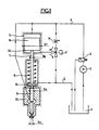
- a pump 2 of the continuous type draws the diesel fuel from a tank 1 and delivers it under a constant pressure, regulated by the regulator 3, in a high pressure line 4 which can supply one or more injector holders identical to that shown on the figure.
- the needle injection 9 of section Sa is guided inside the injection nozzle 10, of conventional type, Ss representing the section at the seat.
- the lower part of the cylinder 5, delimited by the piston 6 forms a cavity 13 which can be brought into communication alternately with the high pressure line 4 or with the discharge line 12 by means of a three-way solenoid valve 11 actuated by an appropriate electronic computer.
- the housing of the spring 8 is in constant communication with the discharge circuit 12.
- An adjustable nozzle 14 is placed upstream of the high pressure inlet of the three-way solenoid valve 11.
- the solenoid valve 11 When it is desired to inject, the solenoid valve 11 is excited which then authorizes the high pressure to penetrate into the chamber 13 and at the same time isolates the latter from the discharge 12.
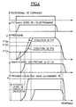
- the start of the lifting movement of the needle injector takes place when the pressure P13 prevailing in the chamber 13, supplied by the solenoid valve 11, reaches a level P13.0 such that: where P represents the injection pressure and Fro the spring force in the rest position.
- the phase A time is relatively long and, with appropriate technology of three-way solenoid valve, it is easy to obtain a solenoid opening time less than the time of phase A which this frees the response time of the solenoid valve to its opening. This is obtained by the dimensioning of the members, and as a last resort by the action on the adjustable nozzle 14 which makes it possible to amplify if necessary the duration of phase A compared to the time of opening of the solenoid valve.
- the pressure P13 is higher than P13.0 the injector opens and the injection takes place at constant pressure.
- the electrical control signal returns to zero and the solenoid valve returns to rest, interrupting the communication of the chamber 13 with the high pressure P and putting this same chamber in communication with the discharge; the pressure P13 then drops rapidly and when it reaches a value P13, f such that .-, (Kx being the additional force due to the contraction of the spring) the injector needle begins to close; the pressure at 13 drops suddenly and the high pressure prevailing in 5 exerts a closing force which is added to the return force of the spring 8, so that the closing of the injector is very rapid.
- the general principle resides in the fact of shifting the opening of the needle of the injector relative to the opening movement of the solenoid valve by using hydraulic delays while that the closing of the needle is directly controlled by the closing of the solenoid valve.
- the same general principle is kept by amplifying it, which makes it possible, by the addition of two differential pistons, to authorize the discharge of the capacity around the needle.
- injector at the end of injection giving rise to an even faster needle closure and giving the injector holder positive flow security, that is to say in the event of failure of the injector needle or certain failures of the solenoid valve, the high injection pressure is interrupted.
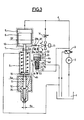
- the body of the injector holder further comprises two concentric bores 20 and 21 of diameter D and d respectively.
- a piston 23 is supported on the piston 22 of the bore 21.
- the piston 22 comprises a T-shaped bore 26 making it possible to connect, depending on the position of the piston 22 in the bore 21, the chamber 18 formed by the bottom of the bore 21 and the lower part of the piston 22 with an annular groove 25 formed in the bore 21. It also comprises an annular groove 24.
- the chamber 18 is supplied by the pressure P of the pump 2 permanently by the conduit 4a, the cavity 17 formed by the upper part of the bore 20 and the top of the piston 23 is connected to the outlet of the solenoid valve 11, which can be alternately set to the pressure P or on the return of leaks, by a conduit 32 from which two conduits 28a and 28b leave going into the chamber 13: on the conduit 28b is placed a non-return valve 30 so that it allows the fuel to flow from the chamber 13 towards the conduit 32; on the duct 28a are interposed a non-return valve 29 and a throttle 14a replacing the throttle 14 of the first version, the non-return valve 29 being placed in such a way that it allows the fuel to flow from the pipe 32 towards the chamber 13. Finally, the groove 25 is connected to the capacity 35 located around the injector needle 9 by a conduit 4b-4c. Furthermore, the volume between the pistons 23 and 26 is in permanent communication by 4d with the leaks.
- the operating principle is as follows: in fig. 3 the system is shown in the injection position, that is to say when the solenoid valve 11 is energized.
- the chamber 13 Before injection, as before, the solenoid valve not being energized, the chamber 13 is in communication with the leaks.
- the pistons 23 and 22 move downward putting the capacity 35 into communication with the high pressure P since the top of the T 26 coincides with the groove 25; the high injection pressure P is therefore established in the injector before the pressure P13.0 is reached and the injector needle begins to open as described in the first version.
- An adaptation of the throttle 14a makes it possible to precisely adjust the phase shifts between the pressure levels P17.0 and P13.0.
- the needle closing kinematics takes place as in the first version except that the closing of the needle is accelerated from the moment when the pressure in the chamber 35 begins to drop as a result of the displacement of the piston 22.
- the piston 22 also provides the injector holder with positive safety since it interrupts the constant pressure P in the cavity 35 between two injections, so if the injector needle 9 gets stuck in the nozzle 10, the fuel under pressure P will only penetrate the cylinder at worst during the very short injection time, limiting the risk of drowning the engine. Finally, if by chance the solenoid valve 11 were to lock in an intermediate position leaving its three channels in communication, the pressure P17 could not be established at a level sufficient to combat the pressure P and to put in communication the top of the T 26 with the annular groove 25.
Landscapes
- Engineering & Computer Science (AREA)
- Chemical & Material Sciences (AREA)
- Combustion & Propulsion (AREA)
- Mechanical Engineering (AREA)
- General Engineering & Computer Science (AREA)
- Physics & Mathematics (AREA)
- Fluid Mechanics (AREA)
- Fuel-Injection Apparatus (AREA)
Applications Claiming Priority (2)
| Application Number | Priority Date | Filing Date | Title |
|---|---|---|---|
| FR8205342A FR2524073B1 (fr) | 1982-03-29 | 1982-03-29 | Injecteur electromagnetique pour moteur diesel donnant lieu a une loi d'injection de type " pression-temps " |
| FR8205342 | 1982-03-29 |
Publications (2)
| Publication Number | Publication Date |
|---|---|
| EP0090739A1 true EP0090739A1 (de) | 1983-10-05 |
| EP0090739B1 EP0090739B1 (de) | 1986-03-12 |
Family
ID=9272506
Family Applications (1)
| Application Number | Title | Priority Date | Filing Date |
|---|---|---|---|
| EP19830400646 Expired EP0090739B1 (de) | 1982-03-29 | 1983-03-29 | Elektromagnetische Einspritzanlage für Dieselmotoren die einen Einspritzverlauf der "Druck-Zeit"-Type erzeugt |
Country Status (4)
| Country | Link |
|---|---|
| EP (1) | EP0090739B1 (de) |
| DE (1) | DE3362491D1 (de) |
| ES (1) | ES8402049A1 (de) |
| FR (1) | FR2524073B1 (de) |
Cited By (4)
| Publication number | Priority date | Publication date | Assignee | Title |
|---|---|---|---|---|
| EP0196265A3 (de) * | 1985-03-25 | 1989-06-07 | Stanadyne Inc. | Speichereinspritzventil |
| US4917352A (en) * | 1987-05-12 | 1990-04-17 | Regie Nationale Des Usines Renault | Injector for engine with spark ignition and direct injection |
| DE4341739C1 (de) * | 1993-12-08 | 1995-03-30 | Mtu Friedrichshafen Gmbh | Einspritzsystem |
| WO1998005858A1 (fr) * | 1996-08-07 | 1998-02-12 | Froment Jean Louis | Dispositif d'amelioration de la dynamique d'injection de combustible pour les moteurs diesel equipes de pompes d'injection a debit pulse |
Citations (4)
| Publication number | Priority date | Publication date | Assignee | Title |
|---|---|---|---|---|
| FR861772A (de) * | 1941-02-26 | |||
| FR2277245A1 (fr) * | 1974-07-02 | 1976-01-30 | Sulzer Ag | Dispositif d'injection de carburant de moteur diesel |
| US4129256A (en) * | 1977-09-12 | 1978-12-12 | General Motors Corporation | Electromagnetic unit fuel injector |
| GB2051229A (en) * | 1979-06-01 | 1981-01-14 | Maschf Augsburg Nuernberg Ag | Fuel Injection Device for an Internal Combustion Engine |
-
1982
- 1982-03-29 FR FR8205342A patent/FR2524073B1/fr not_active Expired
-
1983
- 1983-03-28 ES ES521051A patent/ES8402049A1/es not_active Expired
- 1983-03-29 DE DE8383400646T patent/DE3362491D1/de not_active Expired
- 1983-03-29 EP EP19830400646 patent/EP0090739B1/de not_active Expired
Patent Citations (4)
| Publication number | Priority date | Publication date | Assignee | Title |
|---|---|---|---|---|
| FR861772A (de) * | 1941-02-26 | |||
| FR2277245A1 (fr) * | 1974-07-02 | 1976-01-30 | Sulzer Ag | Dispositif d'injection de carburant de moteur diesel |
| US4129256A (en) * | 1977-09-12 | 1978-12-12 | General Motors Corporation | Electromagnetic unit fuel injector |
| GB2051229A (en) * | 1979-06-01 | 1981-01-14 | Maschf Augsburg Nuernberg Ag | Fuel Injection Device for an Internal Combustion Engine |
Cited By (5)
| Publication number | Priority date | Publication date | Assignee | Title |
|---|---|---|---|---|
| EP0196265A3 (de) * | 1985-03-25 | 1989-06-07 | Stanadyne Inc. | Speichereinspritzventil |
| US4917352A (en) * | 1987-05-12 | 1990-04-17 | Regie Nationale Des Usines Renault | Injector for engine with spark ignition and direct injection |
| DE4341739C1 (de) * | 1993-12-08 | 1995-03-30 | Mtu Friedrichshafen Gmbh | Einspritzsystem |
| WO1998005858A1 (fr) * | 1996-08-07 | 1998-02-12 | Froment Jean Louis | Dispositif d'amelioration de la dynamique d'injection de combustible pour les moteurs diesel equipes de pompes d'injection a debit pulse |
| FR2752268A1 (fr) * | 1996-08-07 | 1998-02-13 | Froment Jean Louis | Dispositif d'amelioration de la dynamique d'injection de combustible pour les moteurs diesel equipes de pompes d'injection a debit pulse |
Also Published As
| Publication number | Publication date |
|---|---|
| ES521051A0 (es) | 1984-01-01 |
| FR2524073B1 (fr) | 1987-01-09 |
| ES8402049A1 (es) | 1984-01-01 |
| EP0090739B1 (de) | 1986-03-12 |
| DE3362491D1 (en) | 1986-04-17 |
| FR2524073A1 (fr) | 1983-09-30 |
Similar Documents
| Publication | Publication Date | Title |
|---|---|---|
| EP0119894B1 (de) | Elektromagnetisch gesteuertes druck-/zeitabhängiges Einspritzsystem für Dieselmotoren, in dem die Ventilnadel durch Entladen und Laden einer Kapazität geführt ist | |
| FR2778699A1 (fr) | Dispositif et procede de commande de soupape | |
| FR2593239A1 (fr) | Systeme d'injection de carburant pour moteur a combustion interne | |
| FR2704600A1 (fr) | Installation d'injection de carburant pour moteur thermique. | |
| FR2750173A1 (fr) | Injecteur de carburant pilote hydrauliquement par une vanne de commande directe a aiguille | |
| FR2742190A1 (fr) | Injecteur de carburant pour moteurs a combustion interne | |
| FR2759740A1 (fr) | Dispositif d'injection a accumulateur pour moteurs a combustion interne multicylindriques | |
| FR2571438A1 (fr) | Injecteur de combustible du type a accumulation | |
| FR2474101A1 (fr) | Dispositif d'injection a regeneration, equipe de valves, pour moteur-fusee | |
| FR2748531A1 (fr) | Injecteur de carburant pour un moteur a combustion interne | |
| FR2805862A1 (fr) | Dispositif d'alimentation en carburant a debit variable | |
| FR2720119A1 (fr) | Système d'injection pour moteur à combustion interne. | |
| EP0898649B1 (de) | Flüssigkraftstoffeinspritzvorrichtung für verbrennungsmotor | |
| EP0090739B1 (de) | Elektromagnetische Einspritzanlage für Dieselmotoren die einen Einspritzverlauf der "Druck-Zeit"-Type erzeugt | |
| EP1312864B1 (de) | Kraftstoffdosierungsvorrichtung für die Einspritzdüse einer Turbomaschine | |
| FR2767932A1 (fr) | Dispositif de regulation de debit volumique et systeme d'injection comportant un tel dispositif de regulation, notamment pour moteur a combustion interne | |
| EP1521913B1 (de) | Vorrichtung und Verfahren zur Regelung der Liefermenge einer Pumpe zur Benzindirekteinspritzung | |
| FR2811023A1 (fr) | Injecteur commande en pression pour injecter du carburant dans un moteur a combustion interne | |
| FR2772430A1 (fr) | Injecteur de carburant pour un moteur a combustion interne | |
| FR2711736A1 (fr) | Dispositif d'injection de combustible liquide pour moteur Diesel. | |
| FR2862120A1 (fr) | Vanne a trois voies et dispositif d'injection de carburant equipe de celle-ci | |
| FR2816665A1 (fr) | Injecteur a dispositif de commande en cascade et alimente a partir d'une rampe commune | |
| FR2865776A1 (fr) | Systeme d'injection de carburant pour un moteur a combustion interne | |
| EP1902214B1 (de) | Druckentlastungsvorrichtung | |
| CA1173315A (fr) | Ensemble pompe-injecteur de combustible pour moteur a combustion interne |
Legal Events
| Date | Code | Title | Description |
|---|---|---|---|
| PUAI | Public reference made under article 153(3) epc to a published international application that has entered the european phase |
Free format text: ORIGINAL CODE: 0009012 |
|
| 17P | Request for examination filed |
Effective date: 19830402 |
|
| AK | Designated contracting states |
Kind code of ref document: A1 Designated state(s): DE GB IT NL SE Designated state(s): DE GB IT NL SE |
|
| GRAA | (expected) grant |
Free format text: ORIGINAL CODE: 0009210 |
|
| AK | Designated contracting states |
Kind code of ref document: B1 Designated state(s): DE GB IT NL SE |
|
| ITF | It: translation for a ep patent filed | ||
| REF | Corresponds to: |
Ref document number: 3362491 Country of ref document: DE Date of ref document: 19860417 |
|
| PLBE | No opposition filed within time limit |
Free format text: ORIGINAL CODE: 0009261 |
|
| STAA | Information on the status of an ep patent application or granted ep patent |
Free format text: STATUS: NO OPPOSITION FILED WITHIN TIME LIMIT |
|
| 26N | No opposition filed | ||
| ITTA | It: last paid annual fee | ||
| PGFP | Annual fee paid to national office [announced via postgrant information from national office to epo] |
Ref country code: NL Payment date: 19930331 Year of fee payment: 11 |
|
| PGFP | Annual fee paid to national office [announced via postgrant information from national office to epo] |
Ref country code: SE Payment date: 19940223 Year of fee payment: 12 |
|
| PG25 | Lapsed in a contracting state [announced via postgrant information from national office to epo] |
Ref country code: NL Effective date: 19941001 |
|
| NLV4 | Nl: lapsed or anulled due to non-payment of the annual fee | ||
| EAL | Se: european patent in force in sweden |
Ref document number: 83400646.2 |
|
| PG25 | Lapsed in a contracting state [announced via postgrant information from national office to epo] |
Ref country code: SE Effective date: 19950330 |
|
| EUG | Se: european patent has lapsed |
Ref document number: 83400646.2 |
|
| PGFP | Annual fee paid to national office [announced via postgrant information from national office to epo] |
Ref country code: GB Payment date: 19960215 Year of fee payment: 14 |
|
| PGFP | Annual fee paid to national office [announced via postgrant information from national office to epo] |
Ref country code: DE Payment date: 19960223 Year of fee payment: 14 |
|
| PG25 | Lapsed in a contracting state [announced via postgrant information from national office to epo] |
Ref country code: GB Effective date: 19970329 |
|
| GBPC | Gb: european patent ceased through non-payment of renewal fee |
Effective date: 19970329 |
|
| PG25 | Lapsed in a contracting state [announced via postgrant information from national office to epo] |
Ref country code: DE Effective date: 19971202 |