EP0090834B1 - Ausdehnbarer bohrer - Google Patents
Ausdehnbarer bohrer Download PDFInfo
- Publication number
- EP0090834B1 EP0090834B1 EP82903081A EP82903081A EP0090834B1 EP 0090834 B1 EP0090834 B1 EP 0090834B1 EP 82903081 A EP82903081 A EP 82903081A EP 82903081 A EP82903081 A EP 82903081A EP 0090834 B1 EP0090834 B1 EP 0090834B1
- Authority
- EP
- European Patent Office
- Prior art keywords
- drill
- members
- diameters
- combination
- chuck
- Prior art date
- Legal status (The legal status is an assumption and is not a legal conclusion. Google has not performed a legal analysis and makes no representation as to the accuracy of the status listed.)
- Expired
Links
Images

Classifications
-
- B—PERFORMING OPERATIONS; TRANSPORTING
- B23—MACHINE TOOLS; METAL-WORKING NOT OTHERWISE PROVIDED FOR
- B23B—TURNING; BORING
- B23B51/00—Tools for drilling machines
- B23B51/009—Stepped drills
-
- Y—GENERAL TAGGING OF NEW TECHNOLOGICAL DEVELOPMENTS; GENERAL TAGGING OF CROSS-SECTIONAL TECHNOLOGIES SPANNING OVER SEVERAL SECTIONS OF THE IPC; TECHNICAL SUBJECTS COVERED BY FORMER USPC CROSS-REFERENCE ART COLLECTIONS [XRACs] AND DIGESTS
- Y10—TECHNICAL SUBJECTS COVERED BY FORMER USPC
- Y10T—TECHNICAL SUBJECTS COVERED BY FORMER US CLASSIFICATION
- Y10T408/00—Cutting by use of rotating axially moving tool
- Y10T408/89—Tool or Tool with support
- Y10T408/892—Tool or Tool with support with work-engaging structure detachable from cutting edge
- Y10T408/8923—Removable central lead
-
- Y—GENERAL TAGGING OF NEW TECHNOLOGICAL DEVELOPMENTS; GENERAL TAGGING OF CROSS-SECTIONAL TECHNOLOGIES SPANNING OVER SEVERAL SECTIONS OF THE IPC; TECHNICAL SUBJECTS COVERED BY FORMER USPC CROSS-REFERENCE ART COLLECTIONS [XRACs] AND DIGESTS
- Y10—TECHNICAL SUBJECTS COVERED BY FORMER USPC
- Y10T—TECHNICAL SUBJECTS COVERED BY FORMER US CLASSIFICATION
- Y10T408/00—Cutting by use of rotating axially moving tool
- Y10T408/89—Tool or Tool with support
- Y10T408/892—Tool or Tool with support with work-engaging structure detachable from cutting edge
- Y10T408/8928—Adjustable
-
- Y—GENERAL TAGGING OF NEW TECHNOLOGICAL DEVELOPMENTS; GENERAL TAGGING OF CROSS-SECTIONAL TECHNOLOGIES SPANNING OVER SEVERAL SECTIONS OF THE IPC; TECHNICAL SUBJECTS COVERED BY FORMER USPC CROSS-REFERENCE ART COLLECTIONS [XRACs] AND DIGESTS
- Y10—TECHNICAL SUBJECTS COVERED BY FORMER USPC
- Y10T—TECHNICAL SUBJECTS COVERED BY FORMER US CLASSIFICATION
- Y10T408/00—Cutting by use of rotating axially moving tool
- Y10T408/89—Tool or Tool with support
- Y10T408/905—Having stepped cutting edges
- Y10T408/906—Axially spaced
- Y10T408/9065—Axially spaced with central lead
Definitions
- the present invention relates to a novel type of drill, particularly for use in the sheet metal and manufacturing industry, which is of the kind that permits drilling of several aperture dimensions with the same drilling unit.
- Certain drilling operations such as, for example, the drilling of sheet metal panels, such as radio and TV chassis, instrument panels and the like, usually requires holes of various dimensions to be drilled in the same plate.
- cone- shaped drill bodies have been proposed which comprise a series of cylindrical sections having a stepwise increasing diameter from the narrow end of the drill body. With such a drill holes having diameters corresponding to the dimensions of the stepwise arranged drill sections of the drill body may be drilled by simply successively drilling a step-by-step larger hole until the desired hole size has been achieved. Drills of this type are, for example, described in the US patents 2,897,696, 3,564,945 and 3,758,222.
- US patent 3,153,356 discloses a multi-piece gun drill having a tip portion detachably secured to a shank portion which may comprise several sections attachable to one another to make up longer or shorter drills according to the depth of the holes to be drilled. Such an extensible drill, however, is restricted to the boring of one hole dimension only.
- a drill utilizing the advantages of the above described combination drill, i.e. that several hole dimensions can be bored without any exchange of drills, but which lacks the mentioned disadvantages and limitations.
- a drill of extensible type comprising a plurality of separate drill members of mutually different drill diameters, which can be put together in any desired combination into a continuous drill body of two or more of the drill members having a stepwise increasing diameter from the outermost drill member.
- the drill members corresponding to the desired hole sizes are selected and assembled into a continuous drill body, which is then mounted in the drilling machine, generally by means of a mounting adapter in the form of a chuck shaft or the like.
- a drill is thus provided which is particularly adapted to precisely the hole dimensions to be drilled and consequently contains no unnecessary drill sections.
- the length of each drill section can be made considerably greater than in the previously known fixed combination drill according to the above US patents without the total drill body becoming unreasonably long for a moderate number of hole sizes.
- each drill member is provided with suitable means for the application of a tool, such as a wrench grip.
- one or more drill members of cutter type may be included in the drill set for plane countersinking for washer seats or the like.
- the last drill of the drill ladder may be such a cutter member.
- the above described extensible drill of the invention has great utility within the sheet metal and manufacturing industry, where very time-consuming work can be saved.
- the inventive concept is, of course, also applicable to other areas and to drilling in other materials.
- the expression "drill member" is also to be considered as comprising comparable cutter tools and the like.
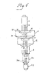
- Fig. 1 shows six drill members designated by the letters A-F having stepwise increasing drill diameters in said order.
- Each drill member A-F comprises a cutting portion with cutting edges 1 and a mounting portion in the form of a central thread tap 2 projecting from the upper part of the cutting portion.
- the drill members are provided with a threaded axial central recess 3 arranged to receive the thread tap 2 of another drill member.
- the lower part of the drill members are terminated by a plane end portion 4.
- the cutting portion of the drill members are teminated by a corresponding plane surface 5, from which the thread tap 2 protrudes.
- the drill member A or the so-called starting drill, comprises two cutting sections 6 and 7 having different diameters.
- the drill member A may, of course, also be made as two separate drill members, as is shown in Fig. 4 (A i , A 2 ).
- the number of cutting edges on the drill members naturally vary with their diameters, and it may be suitable to have two cutting edges on the thinner drill members and three to four on the thicker ones.
- the drill members A-C are illustrated as having two cutting edges, while the drill members D-F have three cutting edges. Of course, both the shape and number of the cutting edges may be varied.
- the drill members A-F are further provided with wrench grips 8 in the upper part of the cutting portion to facilitate the assembly and disassembly, respectively, of the drill members, as will be described in more detail below.
- the drill members A-F in Fig. 1 may be combined with each other in arbitrary manner, the starting drill A, however, always being used as the outermost drill member.
- Two drill members A-F are assembled by screwing the tread tap 2 of one drill member into the treaded recess 3 of the succeeding drill member in the desired combination.
- the threaded recess 3 is somewhat deeper than the length of the thread tap, so that when two drill members have been screwed together the lower end face 4 of one drill member contacts the upper end face 5 of the other.
- Fig. 2-4 examples of various combinations of drill members A-F in Fig. 1 are shown.
- the drill members A, B and D are combined, while the drill body of Fig. 3 comprises the drill members A, D och F.
- the drill members A i , A 2 (corresponding to A in Fig. 1), B, E and F are included.
- the starting drill consists of two separate drill sections A, and A 2 , which make it possible to change the dimension of the proper starting drill A,. Due to the thin dimension of the drill member A, its thread tap 2a, must usually be made narrow. The other thread taps 2 as well as the recesses 3, otherwise have the same dimension to render the combinableness of the invention possible.
- the wrench grips 8, which suitably may consist of two opposed chamfered portions in the upper part of the drill members, facilitate the assembly and in particular, the disassembly of the drill members.
- the extensible drill of the invention may be used in hand drilling machines as well as column and radial drilling machines.
- a drill or chuck fastener 9 which in one end thereof is provided with a threaded, axial recess 10, is screwed onto the top drill member, i.e. the one having the largest dimension.
- the shape of the drill or chuck fastener 9 is adapted to the fastening device or chuck of the drill machine and may, for example, for fixing in a column drilling machine be tapered.
- the length of the drill or chuck fastener is also determined by the hole depth to be drilled, i.e. the thickness of the workpiece to be drilled.
- drill or chuck fasteners 9 of varying length are provided in the drill set.
- one or more drill members designed as drill steels or cutter means for plane countersinking may be included in a drill set according to the invention.
- the last drill member, i.e. of the largest diameter, in a drill ladder A-F may be designed for such plane countersinking.
- the dimensions of the drill members in the extensible drill ladder of the invention may be varied to suit various needs.
- a starting drill of about 4-10 mm (depending on whether a hand drilling machine or a fixed drilling machine is to be used) may be suitable, the other drill members having a stepwise increasing diameter of up to about 80-100 mm.
- the chuck fastener 9 is screwed on to the drill member F as above and the whole unit is fixed in the drilling machine.
- Each hole is then gradually bored to the desired size by successive through-boring with the drill members A, D, F until the desired hole size has been achieved.
- the whole drill ladder may be assembled, which in the shown case permits seven differnt hole diameters.
- the drill sets for the extensible drill according to the invention may, of course, contain more than the six drill members A-F according to Fig. 1. Further, the length of each drill member maybe varied depending on the material thickness to be worked. The number of drill members that may be included in a drill ladder will then, of course, be correspondingly restricted, as such a drill ladder otherwise would become too long. Also, other drill members than the starting drill A may comprise a fixed combination of cutting sections having different diameters, although in such a case the flexibility of that extensible drill will be reduced correspondingly.
Landscapes
- Engineering & Computer Science (AREA)
- Mechanical Engineering (AREA)
- Drilling Tools (AREA)
- Earth Drilling (AREA)
- Knives (AREA)
- Pharmaceuticals Containing Other Organic And Inorganic Compounds (AREA)
- Saccharide Compounds (AREA)
- Massaging Devices (AREA)
- Drilling And Boring (AREA)
- Buildings Adapted To Withstand Abnormal External Influences (AREA)
Claims (10)
Priority Applications (1)
| Application Number | Priority Date | Filing Date | Title |
|---|---|---|---|
| AT82903081T ATE13986T1 (de) | 1981-10-12 | 1982-10-11 | Ausdehnbarer bohrer. |
Applications Claiming Priority (2)
| Application Number | Priority Date | Filing Date | Title |
|---|---|---|---|
| SE8106030 | 1981-10-12 | ||
| SE8106030A SE426148B (sv) | 1981-10-12 | 1981-10-12 | Byggbart borr |
Publications (2)
| Publication Number | Publication Date |
|---|---|
| EP0090834A1 EP0090834A1 (de) | 1983-10-12 |
| EP0090834B1 true EP0090834B1 (de) | 1985-06-26 |
Family
ID=20344768
Family Applications (1)
| Application Number | Title | Priority Date | Filing Date |
|---|---|---|---|
| EP82903081A Expired EP0090834B1 (de) | 1981-10-12 | 1982-10-11 | Ausdehnbarer bohrer |
Country Status (12)
| Country | Link |
|---|---|
| US (1) | US4561812A (de) |
| EP (1) | EP0090834B1 (de) |
| JP (1) | JPS58501666A (de) |
| AT (1) | ATE13986T1 (de) |
| CA (1) | CA1192063A (de) |
| DE (1) | DE3264442D1 (de) |
| DK (1) | DK268383D0 (de) |
| FI (1) | FI832040A0 (de) |
| IT (2) | IT8253787V0 (de) |
| NO (1) | NO832108L (de) |
| SE (1) | SE426148B (de) |
| WO (1) | WO1983001215A1 (de) |
Cited By (1)
| Publication number | Priority date | Publication date | Assignee | Title |
|---|---|---|---|---|
| CN104107937A (zh) * | 2013-04-19 | 2014-10-22 | 苏州文鼎模具有限公司 | 一种可更换钻孔刃的阶梯钻 |
Families Citing this family (39)
| Publication number | Priority date | Publication date | Assignee | Title |
|---|---|---|---|---|
| US5326196A (en) * | 1993-06-21 | 1994-07-05 | Noll Robert R | Pilot drill bit |
| JP2922847B2 (ja) * | 1996-06-05 | 1999-07-26 | 株式会社ミヤナガ | 多段ビット用ストッパー |
| ATE235985T1 (de) * | 1999-08-03 | 2003-04-15 | Kennametal Inc | Bohrer mit auswechselbarem schneidkopf |
| WO2001010587A1 (en) * | 1999-08-11 | 2001-02-15 | Andre Jurgens | Drill bits |
| DE20015550U1 (de) | 2000-09-08 | 2000-10-26 | Quanz, Reiner, 42859 Remscheid | Stufenbohrer |
| DE10207257B4 (de) * | 2002-02-21 | 2021-02-18 | Kennametal Inc. | Rundlaufschneidwerkzeug mit auswechselbarem Schneideinsatz |
| US7309196B2 (en) * | 2004-10-05 | 2007-12-18 | Kennametal Inc. | Modular drill |
| GB0423942D0 (en) * | 2004-10-28 | 2004-12-01 | J & G Hall Ltd | Drills |
| US20070020057A1 (en) * | 2005-07-25 | 2007-01-25 | Yih Troun Enterprise Co., Ltd. | Drill bit with multiple stepped cutting edges |
| US7909547B2 (en) * | 2005-10-08 | 2011-03-22 | Milwaukee Electric Tool Corporation | Replaceable tip for a bit or auger bit |
| US20070264094A1 (en) * | 2006-05-09 | 2007-11-15 | Seeley Scott C | Unibit with replacement blade |
| US8388280B1 (en) * | 2007-10-04 | 2013-03-05 | Orlo Ison | Step drill bit |
| US8702357B2 (en) * | 2009-02-10 | 2014-04-22 | Kennametal Inc. | Multi-piece drill head and drill including the same |
| US8622666B2 (en) * | 2009-08-11 | 2014-01-07 | Combined Producers Co. #1 Inc. | Adjustable step drill bit |
| US8926237B2 (en) | 2011-07-11 | 2015-01-06 | Kennametal Inc. | Multi-piece twist drill head and twist drill including the same |
| US20140290798A1 (en) * | 2013-04-02 | 2014-10-02 | David Hilker | Triple cutter router bit |
| DE102013205889B3 (de) | 2013-04-03 | 2014-05-28 | Kennametal Inc. | Kupplungsteil, insbesondere Schneidkopf für ein Rotationswerkzeug sowie ein derartiges Rotationswerkzeug |
| US9731358B2 (en) | 2013-06-06 | 2017-08-15 | Milwaukee Electric Tool Corporation | Step drill bit |
| EP2826580A1 (de) * | 2013-07-17 | 2015-01-21 | Werkzeug Pichler GmbH & Co. KG | Bohrstift mit stufenförmigem Bohrbereich |
| DE102013220884B4 (de) | 2013-10-15 | 2022-02-17 | Kennametal Inc. | Modulares Trägerwerkzeug sowie Werkzeugkopf |
| DE102014206796B4 (de) | 2014-04-08 | 2020-10-15 | Kennametal Inc. | Rotationswerkzeug, insbesondere Bohrer sowie Schneidkopf für ein solches Rotationswerkzeug |
| CN104646728A (zh) * | 2014-12-29 | 2015-05-27 | 苏州用朴合金工具有限公司 | 一种锥形阶梯钻头 |
| DE102015211744B4 (de) | 2015-06-24 | 2023-07-20 | Kennametal Inc. | Rotationswerkzeug, insbesondere Bohrer, und Schneidkopf für ein solches Rotationswerkzeug |
| CN105195794A (zh) * | 2015-09-29 | 2015-12-30 | 泰州市华诚钨钼制品有限公司 | 一种钨合金非标杆 |
| US10071430B2 (en) | 2015-10-07 | 2018-09-11 | Kennametal Inc. | Cutting head, rotary tool and support for the rotary tool and for the accommodation of the cutting head |
| USD798922S1 (en) | 2015-10-07 | 2017-10-03 | Kennametal Inc. | Cutting head for rotary drill |
| US9937567B2 (en) | 2015-10-07 | 2018-04-10 | Kennametal Inc. | Modular drill |
| USD798921S1 (en) | 2015-10-07 | 2017-10-03 | Kennametal Inc. | Cutting head for modular drill |
| CN106958577A (zh) * | 2017-05-18 | 2017-07-18 | 响水县海源紧定衬套制造有限公司 | 一种实用型紧定套 |
| US10799958B2 (en) | 2017-08-21 | 2020-10-13 | Kennametal Inc. | Modular rotary cutting tool |
| CN108465851A (zh) * | 2018-04-16 | 2018-08-31 | 南京汇龙五金工具制造有限公司 | 一种便于安装的麻花钻 |
| US11273501B2 (en) | 2018-04-26 | 2022-03-15 | Milwaukee Electric Tool Corporation | Step drill bit |
| US11471172B1 (en) | 2018-12-06 | 2022-10-18 | Gary Bram | Osteotomy drill bit to produce an optimally shaped jawbone opening for a dental implant and abutment |
| US12220296B1 (en) | 2018-12-06 | 2025-02-11 | Gary Bram | Osteotomy drill bit to produce an optimally shaped jawbone opening for a dental implant and abutment |
| CN112077370B (zh) | 2019-06-13 | 2024-10-01 | 肯纳金属印度有限公司 | 可转位钻头刀片 |
| USD1088228S1 (en) | 2019-12-05 | 2025-08-12 | Gary Bram | Osteotomy drill |
| CN111774618B (zh) * | 2020-07-03 | 2021-06-18 | 台州市英络克工具有限公司 | 一种台阶钻头 |
| CN115703157A (zh) | 2021-08-17 | 2023-02-17 | 肯纳金属印度有限公司 | 具有冷却剂系统的可转位钻头组件 |
| US12167951B1 (en) | 2022-01-20 | 2024-12-17 | Gary Bram | Osteotomy drill bit to produce an optimally shaped jawbone opening for a dental implant and abutment |
Family Cites Families (11)
| Publication number | Priority date | Publication date | Assignee | Title |
|---|---|---|---|---|
| DE429247C (de) * | 1923-07-12 | 1926-05-20 | Wilhelm Sasse Werkzeugmaschine | Bohrwerkzeug |
| US1620536A (en) * | 1926-03-29 | 1927-03-08 | Gairing Tool Company | Interchangeable boring and counterboring tool |
| US1643679A (en) * | 1926-04-06 | 1927-09-27 | W L Brubaker & Bros Company | Flue-sheet tool |
| US1747117A (en) * | 1927-04-01 | 1930-02-11 | Dayton W Klein | Method of making multiple diameter cut tools |
| US1819949A (en) * | 1930-05-29 | 1931-08-18 | Doehring Stephen Cornelius | Boring ripper |
| FR1014236A (fr) * | 1950-03-08 | 1952-08-12 | Saar Hartmetallwerkzeuge Dipl | Fleuret à plusieurs étages, notamment pour le forage de roches |
| US2897696A (en) * | 1956-01-13 | 1959-08-04 | Henry R Tisserant | Sheet metal panel drill |
| US3153356A (en) * | 1962-12-17 | 1964-10-20 | Howard K Dearborn | Gun drill |
| US3712753A (en) * | 1971-07-15 | 1973-01-23 | M Manzi | Universal replaceable drill for marble, metals and wood |
| GB1368270A (en) * | 1971-12-29 | 1974-09-25 | Vorabbi L | Combined drilling and reaming tool |
| US3758222A (en) * | 1971-12-30 | 1973-09-11 | H Oakes | Drill bit |
-
1981
- 1981-10-12 SE SE8106030A patent/SE426148B/sv not_active IP Right Cessation
-
1982
- 1982-10-08 CA CA000413166A patent/CA1192063A/en not_active Expired
- 1982-10-11 EP EP82903081A patent/EP0090834B1/de not_active Expired
- 1982-10-11 FI FI832040A patent/FI832040A0/fi not_active Application Discontinuation
- 1982-10-11 AT AT82903081T patent/ATE13986T1/de not_active IP Right Cessation
- 1982-10-11 US US06/511,164 patent/US4561812A/en not_active Expired - Fee Related
- 1982-10-11 JP JP57503133A patent/JPS58501666A/ja active Pending
- 1982-10-11 DE DE8282903081T patent/DE3264442D1/de not_active Expired
- 1982-10-11 WO PCT/SE1982/000327 patent/WO1983001215A1/en not_active Ceased
- 1982-10-12 IT IT8253787U patent/IT8253787V0/it unknown
- 1982-10-12 IT IT68198/82A patent/IT1156207B/it active
-
1983
- 1983-06-10 DK DK2683/83A patent/DK268383D0/da not_active Application Discontinuation
- 1983-06-10 NO NO832108A patent/NO832108L/no unknown
Cited By (1)
| Publication number | Priority date | Publication date | Assignee | Title |
|---|---|---|---|---|
| CN104107937A (zh) * | 2013-04-19 | 2014-10-22 | 苏州文鼎模具有限公司 | 一种可更换钻孔刃的阶梯钻 |
Also Published As
| Publication number | Publication date |
|---|---|
| ATE13986T1 (de) | 1985-07-15 |
| DK268383A (da) | 1983-06-10 |
| FI832040A7 (fi) | 1983-06-07 |
| JPS58501666A (ja) | 1983-10-06 |
| EP0090834A1 (de) | 1983-10-12 |
| SE426148B (sv) | 1982-12-13 |
| US4561812A (en) | 1985-12-31 |
| NO832108L (no) | 1983-06-10 |
| IT8268198A0 (it) | 1982-10-12 |
| DK268383D0 (da) | 1983-06-10 |
| CA1192063A (en) | 1985-08-20 |
| WO1983001215A1 (en) | 1983-04-14 |
| IT1156207B (it) | 1987-01-28 |
| IT8253787V0 (it) | 1982-10-12 |
| FI832040L (fi) | 1983-06-07 |
| DE3264442D1 (en) | 1985-08-01 |
| FI832040A0 (fi) | 1983-06-07 |
Similar Documents
| Publication | Publication Date | Title |
|---|---|---|
| US4561812A (en) | Extensible drill | |
| US4815902A (en) | Stepped fluted drill | |
| US5570978A (en) | High performance cutting tools | |
| EP0174089B1 (de) | Abgestufter Bohrer | |
| US5466100A (en) | Multi-stepped power drill bit having handle chuck adaptor | |
| JPH0857774A (ja) | 組合せ型工具 | |
| WO1996004089A3 (de) | Nachbearbeitungswerkzeug für die präzisionsbearbeitung von löchern | |
| JPS6111729B2 (de) | ||
| EP0520111A1 (de) | Bohrer mit Senkgerät | |
| EP0298061B1 (de) | Bohrer und zugehöriger Schneideinsatz | |
| US4823468A (en) | Tool for center-punching and scribing workpieces | |
| US4496165A (en) | Adjustable collet | |
| US4076443A (en) | Cutting tool assembly | |
| EP0202211B1 (de) | Bohrer | |
| US4793745A (en) | Double diameter boring tool | |
| US5758997A (en) | Self-centering indexable drill | |
| WO1999021673A1 (en) | Reamer and method of using the same | |
| KR20050085844A (ko) | 딥 홀 드릴 eb800 | |
| US5409329A (en) | Drill guiding device | |
| US4755088A (en) | Hole saw unjamming tool | |
| CN218192945U (zh) | 高精度双端切削组合铰刀 | |
| JPH03184708A (ja) | 切削加工装置 | |
| JPH0617814U (ja) | 六角穴付ボルト用の段付ドリル | |
| JPH0222174Y2 (de) | ||
| CN88211332U (zh) | 可一次完成钻孔、攻丝工作的刃具 |
Legal Events
| Date | Code | Title | Description |
|---|---|---|---|
| PUAI | Public reference made under article 153(3) epc to a published international application that has entered the european phase |
Free format text: ORIGINAL CODE: 0009012 |
|
| 17P | Request for examination filed |
Effective date: 19830627 |
|
| AK | Designated contracting states |
Kind code of ref document: A1 Designated state(s): AT BE CH DE FR GB LI LU NL SE |
|
| GRAA | (expected) grant |
Free format text: ORIGINAL CODE: 0009210 |
|
| AK | Designated contracting states |
Designated state(s): AT BE CH DE FR GB LI LU NL SE |
|
| PG25 | Lapsed in a contracting state [announced via postgrant information from national office to epo] |
Ref country code: SE Free format text: THE PATENT HAS BEEN ANNULLED BY A DECISION OF A NATIONAL AUTHORITY Effective date: 19850626 |
|
| REF | Corresponds to: |
Ref document number: 13986 Country of ref document: AT Date of ref document: 19850715 Kind code of ref document: T |
|
| REF | Corresponds to: |
Ref document number: 3264442 Country of ref document: DE Date of ref document: 19850801 |
|
| ET | Fr: translation filed | ||
| PG25 | Lapsed in a contracting state [announced via postgrant information from national office to epo] |
Ref country code: LU Free format text: LAPSE BECAUSE OF NON-PAYMENT OF DUE FEES Effective date: 19851031 |
|
| PLBE | No opposition filed within time limit |
Free format text: ORIGINAL CODE: 0009261 |
|
| STAA | Information on the status of an ep patent application or granted ep patent |
Free format text: STATUS: NO OPPOSITION FILED WITHIN TIME LIMIT |
|
| 26N | No opposition filed | ||
| PGFP | Annual fee paid to national office [announced via postgrant information from national office to epo] |
Ref country code: AT Payment date: 19861015 Year of fee payment: 5 |
|
| PG25 | Lapsed in a contracting state [announced via postgrant information from national office to epo] |
Ref country code: AT Effective date: 19871011 |
|
| PG25 | Lapsed in a contracting state [announced via postgrant information from national office to epo] |
Ref country code: LI Effective date: 19871031 Ref country code: CH Effective date: 19871031 Ref country code: BE Effective date: 19871031 |
|
| PGFP | Annual fee paid to national office [announced via postgrant information from national office to epo] |
Ref country code: NL Payment date: 19871031 Year of fee payment: 6 |
|
| BERE | Be: lapsed |
Owner name: LINDEN KARL HUGO Effective date: 19871031 |
|
| REG | Reference to a national code |
Ref country code: CH Ref legal event code: PL |
|
| PG25 | Lapsed in a contracting state [announced via postgrant information from national office to epo] |
Ref country code: NL Effective date: 19890501 |
|
| NLV4 | Nl: lapsed or anulled due to non-payment of the annual fee | ||
| PG25 | Lapsed in a contracting state [announced via postgrant information from national office to epo] |
Ref country code: FR Free format text: LAPSE BECAUSE OF NON-PAYMENT OF DUE FEES Effective date: 19890630 |
|
| REG | Reference to a national code |
Ref country code: FR Ref legal event code: ST |
|
| PGFP | Annual fee paid to national office [announced via postgrant information from national office to epo] |
Ref country code: GB Payment date: 19901008 Year of fee payment: 9 |
|
| PGFP | Annual fee paid to national office [announced via postgrant information from national office to epo] |
Ref country code: DE Payment date: 19901026 Year of fee payment: 9 |
|
| PG25 | Lapsed in a contracting state [announced via postgrant information from national office to epo] |
Ref country code: GB Effective date: 19911011 |
|
| GBPC | Gb: european patent ceased through non-payment of renewal fee | ||
| PG25 | Lapsed in a contracting state [announced via postgrant information from national office to epo] |
Ref country code: DE Effective date: 19920701 |