EP0090853B1 - Elektronisches sicherheitssystem mit geräuschzurückweisung - Google Patents
Elektronisches sicherheitssystem mit geräuschzurückweisung Download PDFInfo
- Publication number
- EP0090853B1 EP0090853B1 EP82903426A EP82903426A EP0090853B1 EP 0090853 B1 EP0090853 B1 EP 0090853B1 EP 82903426 A EP82903426 A EP 82903426A EP 82903426 A EP82903426 A EP 82903426A EP 0090853 B1 EP0090853 B1 EP 0090853B1
- Authority
- EP
- European Patent Office
- Prior art keywords
- frequency
- pulse
- producing
- sweep
- signal
- Prior art date
- Legal status (The legal status is an assumption and is not a legal conclusion. Google has not performed a legal analysis and makes no representation as to the accuracy of the status listed.)
- Expired
Links
Images


Classifications
-
- G—PHYSICS
- G08—SIGNALLING
- G08B—SIGNALLING SYSTEMS, e.g. PERSONAL CALLING SYSTEMS; ORDER TELEGRAPHS; ALARM SYSTEMS
- G08B13/00—Burglar, theft or intruder alarms
- G08B13/22—Electrical actuation
- G08B13/24—Electrical actuation by interference with electromagnetic field distribution
- G08B13/2402—Electronic Article Surveillance [EAS], i.e. systems using tags for detecting removal of a tagged item from a secure area, e.g. tags for detecting shoplifting
- G08B13/2405—Electronic Article Surveillance [EAS], i.e. systems using tags for detecting removal of a tagged item from a secure area, e.g. tags for detecting shoplifting characterised by the tag technology used
- G08B13/2414—Electronic Article Surveillance [EAS], i.e. systems using tags for detecting removal of a tagged item from a secure area, e.g. tags for detecting shoplifting characterised by the tag technology used using inductive tags
-
- G—PHYSICS
- G08—SIGNALLING
- G08B—SIGNALLING SYSTEMS, e.g. PERSONAL CALLING SYSTEMS; ORDER TELEGRAPHS; ALARM SYSTEMS
- G08B13/00—Burglar, theft or intruder alarms
- G08B13/22—Electrical actuation
- G08B13/24—Electrical actuation by interference with electromagnetic field distribution
- G08B13/2402—Electronic Article Surveillance [EAS], i.e. systems using tags for detecting removal of a tagged item from a secure area, e.g. tags for detecting shoplifting
- G08B13/2465—Aspects related to the EAS system, e.g. system components other than tags
- G08B13/2488—Timing issues, e.g. synchronising measures to avoid signal collision, with multiple emitters or a single emitter and receiver
Definitions
- This invention relates to electronic security systems and especially to such systems which are designed to reduce or eliminate inadvertent alarm actuations in response to interference signals.
- the resonant circuit of the tag distorts the field by producing an output in the form of an amplitude modulated pulse at the resonant frequency of the tag when the frequency of the field passes through the tag resonant frequency.
- Receiver 12 is connected to a receiver antenna.
- the signal from the antenna is passed through a bandpass filter 30 which has a pass band equivalent to the frequency output range of the transmitter.
- the filtered received signal is amplified in amplifier 32 and passed to amplitude modulation detector 34 wherein the amplitude modulated pulses are extracted from the received signal.
- An automatic gain control amplifier 36 acts with amplifier 32 to maintain the amplitude of the pulses within a predetermined range.
- FIGURE 2B two tag signal pulses are produced per period of the sweep signal.
- the tag signal pulses are passed by a band pass filter 38 and amplified by amplifier 40.
- Pulse shaping logic 42 outputs square wave pulses shown in FIGURE 2C in response to each of the tag signal pulses.
- synchronous detector 50 sends an output signal to timer 52 which actuates an alarm for a predetermined time duration.
- timer 52 actuates an alarm for a predetermined time duration.
- a time delay circuit could be inserted between detector 50 and timer 52 so that the alarm would sound only after a predetermined number of cycles of the sync. signal are compared to the output from MMV 48.
- noise signals are generated in the vicinity of receiver 12 which are within the frequency range of the receiver. Such signals may be produced by nearby transmitters or the like. When the frequency of the output of transmitter 10 passes near the frequency of the noise source, a pulse may be generated which appears to be a tag circuit pulse.
- structures within the vicinity of the electronic security system such as metal door frames, or the like, may prove to be natural resonant circuits which also produce perturbations which appear similar to tag signals. Consequently, since such noise signals are in part produced by the signal generated by the security system, they will cause interference signals which may appear the same as tag signals, and thus prove to be a difficult problem to overcome. However, such periodic noise signals can be rejected by noise rejection circuit 16 of the present invention.
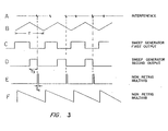
- circuit 16 must be adjusted manually after the electronic security system is in place. When the security system is operative, if any period noisepulses are detected, as by an unwanted actuation of the system alarm, the pulse width of MMV 56 is simply increased until the unwanted alarm actuation ceases. It should also be noted that circuit 16 described herein is effective for eliminating only those interference signals which are produced in response to the downward sweep of the sweep generator 22 output. Clearly, if all interference signals are to be eliminated, MMVs 56 and 64 must be duplicated and made responsive to the leading edge of the generator output on line 28. Of course, sweep function generator 22 could be chosen to produce a sawtooth wave function shown in FIGURE 3F which would produce only a single interference signal per cycle, in which case MMVs 56 and 54 would be effective for eliminating all synchronous noise signals.
Landscapes
- Physics & Mathematics (AREA)
- Engineering & Computer Science (AREA)
- Automation & Control Theory (AREA)
- Computer Security & Cryptography (AREA)
- Electromagnetism (AREA)
- General Physics & Mathematics (AREA)
- Burglar Alarm Systems (AREA)
Claims (8)
Priority Applications (1)
| Application Number | Priority Date | Filing Date | Title |
|---|---|---|---|
| AT82903426T ATE32277T1 (de) | 1981-10-08 | 1982-10-08 | Elektronisches sicherheitssystem mit geraeuschzurueckweisung. |
Applications Claiming Priority (2)
| Application Number | Priority Date | Filing Date | Title |
|---|---|---|---|
| US309715 | 1981-10-08 | ||
| US06/309,715 US4429302A (en) | 1981-10-08 | 1981-10-08 | Electronic security system with noise rejection |
Publications (3)
| Publication Number | Publication Date |
|---|---|
| EP0090853A1 EP0090853A1 (de) | 1983-10-12 |
| EP0090853A4 EP0090853A4 (de) | 1985-07-30 |
| EP0090853B1 true EP0090853B1 (de) | 1988-01-27 |
Family
ID=23199366
Family Applications (1)
| Application Number | Title | Priority Date | Filing Date |
|---|---|---|---|
| EP82903426A Expired EP0090853B1 (de) | 1981-10-08 | 1982-10-08 | Elektronisches sicherheitssystem mit geräuschzurückweisung |
Country Status (5)
| Country | Link |
|---|---|
| US (1) | US4429302A (de) |
| EP (1) | EP0090853B1 (de) |
| AT (1) | ATE32277T1 (de) |
| DE (1) | DE3278052D1 (de) |
| WO (1) | WO1983001331A1 (de) |
Families Citing this family (28)
| Publication number | Priority date | Publication date | Assignee | Title |
|---|---|---|---|---|
| NL8600738A (nl) * | 1986-03-24 | 1987-10-16 | Nedap Nv | Onderdrukking van valse alarmen als gevolg van aanraken. |
| US5300922A (en) * | 1990-05-29 | 1994-04-05 | Sensormatic Electronics Corporation | Swept frequency electronic article surveillance system having enhanced facility for tag signal detection |
| US5239284A (en) * | 1991-01-08 | 1993-08-24 | Kubota Corporation | Antitheft device |
| JP2831181B2 (ja) * | 1991-01-08 | 1998-12-02 | 株式会社クボタ | 盗難防止装置 |
| EP0561062A1 (de) * | 1992-03-17 | 1993-09-22 | Moisei Samuel Granovsky | Verfahren und elektromagnetisches Sicherheitssystem, um geschützte Gegenstände in einem Überwachungsbereich zu entdecken |
| US5349332A (en) * | 1992-10-13 | 1994-09-20 | Sensormatic Electronics Corportion | EAS system with requency hopping |
| US5368554A (en) * | 1992-11-20 | 1994-11-29 | Minnesota Mining And Manufacturing Company | Blood pumping system with selective backflow warning |
| FR2704960A1 (fr) * | 1993-05-03 | 1994-11-10 | Diet Jean Paul | Dispositif de détection de passage d'étiquettes. |
| US5682164A (en) * | 1994-09-06 | 1997-10-28 | The Regents Of The University Of California | Pulse homodyne field disturbance sensor |
| US5521600A (en) * | 1994-09-06 | 1996-05-28 | The Regents Of The University Of California | Range-gated field disturbance sensor with range-sensitivity compensation |
| US5528914A (en) | 1994-09-27 | 1996-06-25 | Sensormatic Electronics Corporation | Security tag and complemental deactivation apparatus |
| BR9604805A (pt) * | 1995-04-07 | 1998-06-09 | Minnesota Mining & Mfg | Sistema de vigilância eletrônica sobre artigos e processo de detectar a presença de uma etiqueta sensibilizada em um corredor de interrogação |
| US5564420A (en) * | 1995-04-14 | 1996-10-15 | Minnesota Mining And Manufacturing Company | Medical device with EMI detection and cancellation |
| US5798693A (en) * | 1995-06-07 | 1998-08-25 | Engellenner; Thomas J. | Electronic locating systems |
| JPH0962952A (ja) * | 1995-08-29 | 1997-03-07 | Maspro Denkoh Corp | 盗難防止システム |
| BR0110648A (pt) * | 2000-05-08 | 2003-04-01 | Checkpoint Systems Inc | Sistema de detecção e identificação de radiofrequência |
| US6373390B1 (en) | 2000-08-08 | 2002-04-16 | Sensormatic Electronics Corporation | Electronic article surveillance tag having arcuate channel |
| US6535130B2 (en) | 2001-04-25 | 2003-03-18 | Sensormatic Electronics Corporation | Security apparatus for electronic article surveillance tag |
| US7704346B2 (en) * | 2004-02-23 | 2010-04-27 | Checkpoint Systems, Inc. | Method of fabricating a security tag in an integrated surface processing system |
| US7119685B2 (en) * | 2004-02-23 | 2006-10-10 | Checkpoint Systems, Inc. | Method for aligning capacitor plates in a security tag and a capacitor formed thereby |
| US7116227B2 (en) * | 2004-02-23 | 2006-10-03 | Checkpoint Systems, Inc. | Tag having patterned circuit elements and a process for making same |
| US8099335B2 (en) * | 2004-02-23 | 2012-01-17 | Checkpoint Systems, Inc. | Method and system for determining billing information in a tag fabrication process |
| US7384496B2 (en) * | 2004-02-23 | 2008-06-10 | Checkpoint Systems, Inc. | Security tag system for fabricating a tag including an integrated surface processing system |
| US7138919B2 (en) * | 2004-02-23 | 2006-11-21 | Checkpoint Systems, Inc. | Identification marking and method for applying the identification marking to an item |
| US7689195B2 (en) * | 2005-02-22 | 2010-03-30 | Broadcom Corporation | Multi-protocol radio frequency identification transponder tranceiver |
| US7633396B2 (en) | 2006-02-07 | 2009-12-15 | Sensormatic Electronics, LLC | Electronic article surveillance tag having an expulsion detrimental substance system with substance routing system |
| US8089362B2 (en) * | 2009-04-08 | 2012-01-03 | Avery Dennison Corporation | Merchandise security kit |
| CN108883998A (zh) | 2016-04-20 | 2018-11-23 | 美国陶氏有机硅公司 | 烷基硅酸锂组合物、涂层及其制备方法 |
Family Cites Families (2)
| Publication number | Priority date | Publication date | Assignee | Title |
|---|---|---|---|---|
| US3828337A (en) | 1973-08-20 | 1974-08-06 | G Lichtblau | Noise rejection circuitry |
| US4117466A (en) | 1977-03-14 | 1978-09-26 | Lichtblau G J | Beat frequency interference rejection circuit |
-
1981
- 1981-10-08 US US06/309,715 patent/US4429302A/en not_active Expired - Fee Related
-
1982
- 1982-10-08 EP EP82903426A patent/EP0090853B1/de not_active Expired
- 1982-10-08 WO PCT/US1982/001449 patent/WO1983001331A1/en not_active Ceased
- 1982-10-08 DE DE8282903426T patent/DE3278052D1/de not_active Expired
- 1982-10-08 AT AT82903426T patent/ATE32277T1/de not_active IP Right Cessation
Also Published As
| Publication number | Publication date |
|---|---|
| DE3278052D1 (en) | 1988-03-03 |
| US4429302A (en) | 1984-01-31 |
| WO1983001331A1 (en) | 1983-04-14 |
| ATE32277T1 (de) | 1988-02-15 |
| EP0090853A1 (de) | 1983-10-12 |
| EP0090853A4 (de) | 1985-07-30 |
Similar Documents
| Publication | Publication Date | Title |
|---|---|---|
| US4429302A (en) | Electronic security system with noise rejection | |
| US4667185A (en) | Wireless synchronization system for electronic article surveillance system | |
| US4476459A (en) | Theft detection method and apparatus in which the decay of a resonant circuit is detected | |
| US4382291A (en) | Surveillance system in which a reflected signal pattern is compared to a reference pattern | |
| US5463376A (en) | System and method for synchronizing a receiver of an electronic article surveillance system and a transmitter thereof | |
| EP0003178B1 (de) | Anwesenheitsüberprüfungssystem | |
| US4660024A (en) | Dual technology intruder detection system | |
| US4612442A (en) | Passive infrared intrusion detection system | |
| US5077548A (en) | Dual technology intruder detection system with sensitivity adjustment after "default" | |
| ES454749A1 (es) | Sistema de seguridad electronico para establecimientos de venta de articulos. | |
| US3696369A (en) | Signal processor | |
| HK1005919B (en) | Periodic pulse discrimination system | |
| EP0058205A1 (de) | Ultraschall-warnsystem | |
| EP0020062A1 (de) | Verfahren und Überwachungssystem zur Feststellung der Anwesenheit eines Empfängers-Rücksenders für elektromagnetische Signale | |
| US4225859A (en) | Method and apparatus for monitoring sound-conducting media | |
| US7123145B2 (en) | Method and apparatus for analysing a signal from a movement detector for determining if movement has been detected in an area under surveillance and an anti-theft system | |
| US3828337A (en) | Noise rejection circuitry | |
| US4290056A (en) | Protective system | |
| CA1295028C (en) | Electronic article surveillance system utilizing synchronous integration | |
| GB1514982A (en) | Signal discrimination circuitry in an electronic security system | |
| JPS6351317B2 (de) | ||
| GB1580412A (en) | Beat frequency interference rejection circuitry | |
| US4129856A (en) | Filter system and method for intrusion alarm | |
| US5729202A (en) | Electronic article-surveillance apparatus and method of operating same | |
| US4414534A (en) | Radio frequency detection circuitry having noise discrimination capability |
Legal Events
| Date | Code | Title | Description |
|---|---|---|---|
| PUAI | Public reference made under article 153(3) epc to a published international application that has entered the european phase |
Free format text: ORIGINAL CODE: 0009012 |
|
| 17P | Request for examination filed |
Effective date: 19830608 |
|
| AK | Designated contracting states |
Designated state(s): AT BE CH DE FR GB LI LU NL SE |
|
| 17Q | First examination report despatched |
Effective date: 19860422 |
|
| RAP1 | Party data changed (applicant data changed or rights of an application transferred) |
Owner name: SENSORMATIC ELECTRONICS CORPORATION |
|
| GRAA | (expected) grant |
Free format text: ORIGINAL CODE: 0009210 |
|
| AK | Designated contracting states |
Kind code of ref document: B1 Designated state(s): AT BE CH DE FR GB LI LU NL SE |
|
| PG25 | Lapsed in a contracting state [announced via postgrant information from national office to epo] |
Ref country code: NL Effective date: 19880127 Ref country code: LI Effective date: 19880127 Ref country code: CH Effective date: 19880127 Ref country code: BE Effective date: 19880127 Ref country code: AT Effective date: 19880127 |
|
| REF | Corresponds to: |
Ref document number: 32277 Country of ref document: AT Date of ref document: 19880215 Kind code of ref document: T |
|
| PG25 | Lapsed in a contracting state [announced via postgrant information from national office to epo] |
Ref country code: SE Effective date: 19880131 |
|
| REF | Corresponds to: |
Ref document number: 3278052 Country of ref document: DE Date of ref document: 19880303 |
|
| ET | Fr: translation filed | ||
| REG | Reference to a national code |
Ref country code: CH Ref legal event code: PL |
|
| NLV1 | Nl: lapsed or annulled due to failure to fulfill the requirements of art. 29p and 29m of the patents act | ||
| PG25 | Lapsed in a contracting state [announced via postgrant information from national office to epo] |
Ref country code: GB Effective date: 19881008 |
|
| PG25 | Lapsed in a contracting state [announced via postgrant information from national office to epo] |
Ref country code: LU Free format text: LAPSE BECAUSE OF NON-PAYMENT OF DUE FEES Effective date: 19881031 |
|
| PLBE | No opposition filed within time limit |
Free format text: ORIGINAL CODE: 0009261 |
|
| STAA | Information on the status of an ep patent application or granted ep patent |
Free format text: STATUS: NO OPPOSITION FILED WITHIN TIME LIMIT |
|
| 26N | No opposition filed | ||
| GBPC | Gb: european patent ceased through non-payment of renewal fee | ||
| PGFP | Annual fee paid to national office [announced via postgrant information from national office to epo] |
Ref country code: LU Payment date: 19910926 Year of fee payment: 10 |
|
| EPTA | Lu: last paid annual fee | ||
| PGFP | Annual fee paid to national office [announced via postgrant information from national office to epo] |
Ref country code: FR Payment date: 19930915 Year of fee payment: 12 |
|
| PGFP | Annual fee paid to national office [announced via postgrant information from national office to epo] |
Ref country code: DE Payment date: 19930916 Year of fee payment: 12 |
|
| PG25 | Lapsed in a contracting state [announced via postgrant information from national office to epo] |
Ref country code: FR Effective date: 19950630 |
|
| PG25 | Lapsed in a contracting state [announced via postgrant information from national office to epo] |
Ref country code: DE Effective date: 19950701 |
|
| REG | Reference to a national code |
Ref country code: FR Ref legal event code: ST |