EP0003178B1 - Anwesenheitsüberprüfungssystem - Google Patents
Anwesenheitsüberprüfungssystem Download PDFInfo
- Publication number
- EP0003178B1 EP0003178B1 EP79300047A EP79300047A EP0003178B1 EP 0003178 B1 EP0003178 B1 EP 0003178B1 EP 79300047 A EP79300047 A EP 79300047A EP 79300047 A EP79300047 A EP 79300047A EP 0003178 B1 EP0003178 B1 EP 0003178B1
- Authority
- EP
- European Patent Office
- Prior art keywords
- output
- signal
- frequency
- input
- receiver
- Prior art date
- Legal status (The legal status is an assumption and is not a legal conclusion. Google has not performed a legal analysis and makes no representation as to the accuracy of the status listed.)
- Expired
Links
Images



Classifications
-
- G—PHYSICS
- G08—SIGNALLING
- G08B—SIGNALLING SYSTEMS, e.g. PERSONAL CALLING SYSTEMS; ORDER TELEGRAPHS; ALARM SYSTEMS
- G08B13/00—Burglar, theft or intruder alarms
- G08B13/22—Electrical actuation
- G08B13/24—Electrical actuation by interference with electromagnetic field distribution
- G08B13/2402—Electronic Article Surveillance [EAS], i.e. systems using tags for detecting removal of a tagged item from a secure area, e.g. tags for detecting shoplifting
- G08B13/2405—Electronic Article Surveillance [EAS], i.e. systems using tags for detecting removal of a tagged item from a secure area, e.g. tags for detecting shoplifting characterised by the tag technology used
- G08B13/2414—Electronic Article Surveillance [EAS], i.e. systems using tags for detecting removal of a tagged item from a secure area, e.g. tags for detecting shoplifting characterised by the tag technology used using inductive tags
-
- G—PHYSICS
- G08—SIGNALLING
- G08B—SIGNALLING SYSTEMS, e.g. PERSONAL CALLING SYSTEMS; ORDER TELEGRAPHS; ALARM SYSTEMS
- G08B13/00—Burglar, theft or intruder alarms
- G08B13/22—Electrical actuation
- G08B13/24—Electrical actuation by interference with electromagnetic field distribution
- G08B13/2402—Electronic Article Surveillance [EAS], i.e. systems using tags for detecting removal of a tagged item from a secure area, e.g. tags for detecting shoplifting
- G08B13/2405—Electronic Article Surveillance [EAS], i.e. systems using tags for detecting removal of a tagged item from a secure area, e.g. tags for detecting shoplifting characterised by the tag technology used
- G08B13/2414—Electronic Article Surveillance [EAS], i.e. systems using tags for detecting removal of a tagged item from a secure area, e.g. tags for detecting shoplifting characterised by the tag technology used using inductive tags
- G08B13/242—Tag deactivation
-
- G—PHYSICS
- G08—SIGNALLING
- G08B—SIGNALLING SYSTEMS, e.g. PERSONAL CALLING SYSTEMS; ORDER TELEGRAPHS; ALARM SYSTEMS
- G08B13/00—Burglar, theft or intruder alarms
- G08B13/22—Electrical actuation
- G08B13/24—Electrical actuation by interference with electromagnetic field distribution
- G08B13/2402—Electronic Article Surveillance [EAS], i.e. systems using tags for detecting removal of a tagged item from a secure area, e.g. tags for detecting shoplifting
- G08B13/2428—Tag details
- G08B13/2434—Tag housing and attachment details
-
- G—PHYSICS
- G08—SIGNALLING
- G08B—SIGNALLING SYSTEMS, e.g. PERSONAL CALLING SYSTEMS; ORDER TELEGRAPHS; ALARM SYSTEMS
- G08B13/00—Burglar, theft or intruder alarms
- G08B13/22—Electrical actuation
- G08B13/24—Electrical actuation by interference with electromagnetic field distribution
- G08B13/2402—Electronic Article Surveillance [EAS], i.e. systems using tags for detecting removal of a tagged item from a secure area, e.g. tags for detecting shoplifting
- G08B13/2465—Aspects related to the EAS system, e.g. system components other than tags
- G08B13/2468—Antenna in system and the related signal processing
- G08B13/2471—Antenna signal processing by receiver or emitter
-
- G—PHYSICS
- G08—SIGNALLING
- G08B—SIGNALLING SYSTEMS, e.g. PERSONAL CALLING SYSTEMS; ORDER TELEGRAPHS; ALARM SYSTEMS
- G08B13/00—Burglar, theft or intruder alarms
- G08B13/22—Electrical actuation
- G08B13/24—Electrical actuation by interference with electromagnetic field distribution
- G08B13/2402—Electronic Article Surveillance [EAS], i.e. systems using tags for detecting removal of a tagged item from a secure area, e.g. tags for detecting shoplifting
- G08B13/2465—Aspects related to the EAS system, e.g. system components other than tags
- G08B13/2488—Timing issues, e.g. synchronising measures to avoid signal collision, with multiple emitters or a single emitter and receiver
Definitions
- This invention relates to a presence sensing system and more particularly to such a system for enabling an alarm to be actuated when a security device is present in a controlled zone.
- British Patent No. 1212 504 discloses an elementary system for theft detection in buildings in which an article is provided with a miniature oscillator or bug which is energised when it enters an electromagnetic induction field generated across or adjacent an exit to the building. An alarm is sounded when a bug is detected.
- a detector is arranged to detect the frequency generated by the oscillator. This basic system suffers from the disadvantage that no means for checking the authenticity of signals received by the detector is provided and the detector is easily triggered by spurious signals.
- the preamble of Claim 1 corresponds to the disclosure of this patent.
- U.S. Patent No. 3818472 discloses a system in which a passive tag comprising an inductance capacitance circuit is employed as a bug and this "rings" upon entry into a protected area which is radiated with a pulsed transmitted frequency. The signal radiated by the ringing effect is detected by a receiver to detect presence of a bug in the protected area. Means are provded for detecting a spurious signal which actuates a false alarm indicator.
- U.S. Patent No 3745569 discloses a communication system comprising an interrogator unit and a transponder.
- the transponder has a receiver 120 and coding means 198, 212, 202 comprising a divider 198 having an input arranged to receive a signal derived from the output of the receiver 120.
- Transmitter 38, Fig. 2 of the interrogator unit transmits a pulse modulated carrier signal to the transponder, the pulse repetition frequency being 4kHz for example.
- the transponder output is a pulse train with each pulse corresponding to a respective input pulse, but with certain pulses deleted in accordance with the code.
- the invention seeks to provide a presence sensing system which is resistant to actuation by spurious signals.
- the system is particularly suitable for application to antishop-lifting applications in which a security device is attachable to an article to enable it to be detected by a detector when it enters a controlled zone provided at for example an exit of the shop.
- a security device is attachable to an article to enable it to be detected by a detector when it enters a controlled zone provided at for example an exit of the shop.
- the principles of this invention are however applicable to other purposes.
- a local presence sensing system comprising a detector having a transmitter for transmitting an interrogation signal and a receiver for receiving a local presence indicating signal, both said signals being in the inductive communication frequency band, and a receiver/transmitter device the present of which is to be detected adapted to receive the interrogation frequency and to transmit said presence indicating signal in response thereto, characterised in that the detector further comprises a phase lock loop circuit having a first input coupled with the output of the receiver, a second input for the output of a variable frequency oscillator and an output for providing a phase locked signal indicative of phase or frequency coherence between the signals on said first and second inputs and an alarm circuit coupled with the output of the phase lock loop circuit actuable in response to said phase locked signal and in that the receiver/transmitter device comprises means for synthesizing the presence indicating signal from the received interrogation signal by multiplication or division of the interrogation frequency by an integral number (including 1), said synthesizing means being connected between the output of the receiver and
- the advantages offered by the invention are that the system is resistant to actuaion by spurious signals and by employing a phase lock loop highly selective frequency discrimination is provided without requiring complex fitering techniques.
- the frequency generator comprises an oscillator capable of oscillating within a restricted frequency range and controllable by said phase lock loop in response to a received presence indicating signal to lock the oscillator to a received signal within said restricted frequency range and provide said phase locked signal.
- the detector can have a predetermined frequency range which permits a slight tolerance of the detectable frequency.
- the interrogation frequency may be transmitted in pulsed carrierform.
- the received pulses may be passed via an integrator to the alarm such that alarm actuation occurs only after receipt of a predetermined number of pulses.
- means may be provided for checking for the presence of a spurious received signal at the wanted frequency prior to a transmission pulse and for rejecting a following presence indicating signal upon detection of such a spurious signal.
- Said means for checking for the presence of a received spurious signal at the wanted frequency prior to a transmission pulse may comprise a pulse generator and inhibit means.
- a gate circuit having a first input coupled to the output of the pulse generator and a second input coupled to the output of the phase lock loop provides a inhibit signal upon occurrence of signals on both said inputs; a hold circuit is also provided responsive to said inhibit signal to maintain the inhibit signal during the period of the next transmission pulse.
- the wanted frequency is meant the frequency of the local presence indicating signal.
- the coding may be effected by stepping a register as a function of the received frequency to provide an output on one coding line in turn and by providing a through connection to an output line from preset ones of the coding lines to enable a predetermined code to be routed to the output for modulating a transmit pulse.
- the presence indicating device and detector are operable in the inductive communication frequency band between 10 Khz and 150 KHz at which frequency advantageous signal penetration occurs enabling the presence indicating device to be detected even when carried for example inside a bag.
- Presence indicating devices for a presence sensing system are preferably small security tags of integrated circuit form for attachement to an article and comprising a receiver aerial coupled to a receiver tuned to 132 KHz.
- the output of the receiver is coupled to a frequency divider which divides the receiver frequency by two which divided frequency is fed to a transmitter where it is transmitted via a transmitter aerial.
- the transmitter aerial of a detector circuit is arranged to irradiate a zone to be controlled.
- the tag When the tag is present in the irradiated zone it receives the signal, divides the signal by two in the divider and transmits the divided signal which is received by the aerial of a detector circuit.
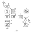
- a detector circuit comprises a master oscillator 30 which generates a fixed frequency carrier signal at 132 KHz which forms one input to an AND gate 31.
- a timing circuit 32 is coupled to a monostable trigger circuit 33 the output of which is coupled to a second input of the AND gate 31.
- the output from the AND gate is a pulsed carrier signal which is coupled to an output drive unit 34 where it is amplified before coupling to a transmitter aerial 35.
- a receiver 36 is tuned to detect a signal which is an exact harmonic or sub harmonic of the transmitted frequency (in this particular case 66 KHz) as received by a receive aerial 37.
- the detector circuit also comprises means for responding to a code transmitted by a tag.
- phase lock loop 38 which is coupled with an oscillator 40 which has a frequency of approximately 66 KHz but which has a restricted variable frequency range to permit "pulling" into phase coherence in response to a received signal within a predetermined narrow frequency range.
- oscillator 40 which has a frequency of approximately 66 KHz but which has a restricted variable frequency range to permit "pulling" into phase coherence in response to a received signal within a predetermined narrow frequency range.
- This enables the phase lock loop to lock to a wanted signal but to ignore an interfering signal provided it falls outside of the narrow pulling range. In this way the phase lock loop acts as a very high grade filter.
- the phase lock loop provides an output signal of logic "1" when phase locking occurs.
- a gating circuit 41 has been incorporated.
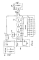
- the gating circuit is shown in greater detail in Figure 2.
- the timing circuit 32 forms a pulse repetition generator having an output coupled to the input of the monostable trigger circuit 33 and an output coupled to one input of a two input AND gate 46 and to the input of a trigger circuit 44 the output of which is coupled to one input of a 3 input AND gate 45.
- the second input of the AND gate 46 is coupled to the output of the phase lock loop 38.
- the output of the gate 46 is coupled to the input of a monostable trigger circuit 47 which provides a normal output of logic "1" to one input of the gate 45.
- the third input of the gate 45 is coupled to the output of the phase lock loop 38 and the output of the gate 45 forms an output for feeding an integrator 48 and latching alarm circuit 49 of Figure 1.
- the output 51 of the latching alarm circuits 49 are coupled to an alarm.
- the gating circuit operates as follows and pulse diagrams at points on Figure 2 are indicated in Figure 3.
- the timing circuit 32 controls the generation of monostable trigger circuits 33 and 44 to produce output waveforms a b and c.
- the timing circuit generates an output immediately prior to the transmit pulse from the monostable trigger circuit 33. If a logic "1" output occurs from the phase lock loop 38 at the same time as a logic "1" pulse from the timing circuit 32 then the gate 46 provides a logic "1" output to the monostable trigger circuit 47 which is triggered to provide a "0" output for a predetermined inhibit period to the gate 45.
- the inhibit period is long enough to maintain the gate 45 non conductive until after the expiry of the next window pulse (waveform c) and no output is provided from gate 45 to the integrate circuit 48. If however, during the space between pulses no output occurs from the phase lock loop thereby indicating that no spurious interfering signal is present then a "0" output from the gate 46 prevents triggering of the trigger 47 and a "1" is provided thereby at the input of the gate 45.
- the output pulses from the timing circuit 32 trigger the trigger circuit 44 which provides a window pulse of logic "1" for a duration longer than the transmitted pulse to be routed to the input of the AND gate 45.
- the phase lock loop locks to the received signal and provides a "1" to the third input of the gate 45 which provides a "1" output to the latching alarm circuit integrator 48 and latching alarm circuit 49.
- the integrator is arranged to trigger the latching alarm circuit only after a predetermined number of successive pulses have been fed thereto for example three pulses.
- the window pulse is of longer duration then the transmitted pulse in order to accommodate the delay in turn off time of the output stage of the phase lock loop.
- Figure 4 shows circuitry which enables a preset identifying code to be transmitted to enable identification of individual tags in the detector.
- a receiver 61 is coupled to a coding circuit and the receiver signal is used as a clock for the coding.
- the output of the receiver is coupled via a divide by 2 circuit 62 to one input of a two input AND gate 63 the output of which is coupled to a transmitter 64.
- the output of the circuit 62 is connected to the input of a divide by 82 network 65 the output of which is coupled to a four bit binary counter 66.
- the outputs of the counter 66 are coupled to a decimal decoder 67 which provides an output on a particular one of eight output lines corre- - sponding to each of the binary codes.
- Each of the eight output lines is coupled via a diode of a data coding chip 68, which forms a read only memory to a common output which is coupled to the other input of the AND gate 63.
- Some of the diodes are "blown" in the conventional manner to provide a unique eight bit serially coded pulse train in response to stepping of the decoder 67.
- a reset circuit 69 is coupled to the divide by 82 network and binary counter 66 and is fed from the receiver and is arranged to reset the divider and counter in the absence of a received signal.
- a 66 KHz carrier signal derived from the divider 62 forms one input to the 2 input AND gate 63.
- the divider circuit 65 steps the counter 66 at intervals of approximately 2.5m sec.
- the outputs from the counter chain are converted from binary into decimal by the decoder.
- the eight sequential outputs of 2.5m sec duration each from the decoder provide the means of reading the tag code from the single read only memory formed by the data coding chip 68.
- the eight bit serial coded pulse train forms the second input to the two input AND gate 63 which provides an output 66 KHz carrier pulsed in accordance with the particular code of the tag.
- the means of the detector circuit for responding to the tag code may be a simple register which will respond to the coded carrier and provide an indication of the code for identification purposes.
- FIG. 5 shows a cross sectional view of a tag which comprises a moulded housing 71 with an encapsulated circuit board 72 with the receiver/ transmitter and associated divider/coding circuitry at one end and a locking device 73 at the other end for receiving and securing a headed fastener 74 inserted from one side.
- the fastener is passed through a garment into the locking device to secure the assembly on an article the un-authorised removal of which is to be detected.
- the housing is also provided with a nylon strap 75 having holes therethrough which can serve to secure the device to other articles by passing the strap through a hole therein and passing the headed fastener 74 through a hole in the strap and into the locking device 73.
- the fastener 74 can only be removed from the locking device with a special tool.
- the detector employs a transmit aerial as shown in Figure 6 wound on a flat hollow rectangular former of approximate dimensions 10 cms by 18 cms.
- the coil is connected in parallel with a capacitor and a single turn coupling coil is transformer coupled to the output of the transmitter.
- Tuning is effected by distorting the former and the former when tuned is filled with foam to retain its shape. This enables the complete aerial to be recessed into the floor or suspended overhead and there is no requirement for the transmitter/receiver device to be brought in the immediate vicinity of or to pass through an inductive loop.
- the receiver aerial is a tuned ferrite rod.
- the active presence indicating receiver/transmitter device may be powered by any suitable means e.g. by internal replacable or rechargeable batteries by self energisation from the received signal or by means of an integral photoelectric or thermo-electric generator.
- the presence indicating device which may be in the form of a security tag may be arranged to be securely attachable to an article by any suitable form of locking means e.g. a key actuated lock to enable removal only by authorised personnel at for example a sales point.
- the indicating device may be provided with means for switching off when removed from the article. Such means may conveniently be actuated upon release of the locking means.
- the system is particularly advantageous in that:-
- the presence indicating tag circuit could be arranged to transmit at the same frequency as the received signal provided suitable shielding is provided between the transmitter aerial and receiver aerial. In this case the transmitted signal could be compared directly with the received signal in the detector.
- the system is suitable for use for example in connection with the opening of doors upon approach of a person or vehicle provided with a suitable presence indicating tag, for identifying articles bearing such tags passing along a production line, for clocking in and out of factories for security of keys in hotels where each key could be fitted with a tag, for operating an alarm at hotel doorways, and many other purposes.
Landscapes
- Physics & Mathematics (AREA)
- Engineering & Computer Science (AREA)
- Automation & Control Theory (AREA)
- Computer Security & Cryptography (AREA)
- Electromagnetism (AREA)
- General Physics & Mathematics (AREA)
- Signal Processing (AREA)
- Burglar Alarm Systems (AREA)
- Photoreceptors In Electrophotography (AREA)
- Acyclic And Carbocyclic Compounds In Medicinal Compositions (AREA)
Claims (7)
Applications Claiming Priority (2)
| Application Number | Priority Date | Filing Date | Title |
|---|---|---|---|
| GB113578 | 1978-01-11 | ||
| GB113578 | 1978-01-11 |
Publications (2)
| Publication Number | Publication Date |
|---|---|
| EP0003178A1 EP0003178A1 (de) | 1979-07-25 |
| EP0003178B1 true EP0003178B1 (de) | 1989-05-24 |
Family
ID=9716785
Family Applications (1)
| Application Number | Title | Priority Date | Filing Date |
|---|---|---|---|
| EP79300047A Expired EP0003178B1 (de) | 1978-01-11 | 1979-01-11 | Anwesenheitsüberprüfungssystem |
Country Status (9)
| Country | Link |
|---|---|
| US (1) | US4260983A (de) |
| EP (1) | EP0003178B1 (de) |
| AU (1) | AU525953B2 (de) |
| CA (1) | CA1117633A (de) |
| DE (1) | DE2967688D1 (de) |
| DK (1) | DK10479A (de) |
| GB (1) | GB2017454B (de) |
| NO (1) | NO147353C (de) |
| ZA (1) | ZA7994B (de) |
Families Citing this family (36)
| Publication number | Priority date | Publication date | Assignee | Title |
|---|---|---|---|---|
| ZA813317B (en) * | 1980-05-19 | 1982-05-26 | Tag Radionics Ltd | Coded information arrangement |
| US4471344A (en) * | 1980-10-09 | 1984-09-11 | Ici Americas Inc. | Dual frequency anti-theft system |
| CA1190970A (en) * | 1980-10-09 | 1985-07-23 | Harold B. Williams | Dual frequency anti-theft system |
| FR2492539A1 (fr) * | 1980-10-20 | 1982-04-23 | Morey Gilles | Procede et systeme de detection notamment pour installations de surveillance ou automatismes |
| US4481428A (en) * | 1981-05-19 | 1984-11-06 | Security Tag Systems, Inc. | Batteryless, portable, frequency divider useful as a transponder of electromagnetic radiation |
| ZA825021B (en) * | 1981-07-14 | 1983-06-29 | Tag Radionics Ltd | Coded information arrengements |
| NL8200138A (nl) * | 1982-01-14 | 1983-08-01 | Nedap Nv | Detectiestelsel. |
| DK148106C (da) * | 1983-04-12 | 1987-10-19 | 2 M Security System Aps | Tyverisikringsanlaeg, navnlig til butiksarealer |
| EP0455315A3 (en) * | 1983-12-06 | 1992-01-22 | Mars Incorporated | Tokens and token handling devices |
| US4727360A (en) * | 1985-09-13 | 1988-02-23 | Security Tag Systems, Inc. | Frequency-dividing transponder and use thereof in a presence detection system |
| US4654641A (en) * | 1985-09-13 | 1987-03-31 | Security Tag Systems, Inc. | Frequency divider with single resonant circuit and use thereof as a transponder in a presence detection system |
| US4670740A (en) * | 1985-11-04 | 1987-06-02 | Security Tag Systems, Inc. | Portable, batteryless, frequency divider consisting of inductor and diode |
| GB8602913D0 (en) * | 1986-02-06 | 1986-03-12 | Cotag International Ltd | Aerial systems |
| US4724427A (en) * | 1986-07-18 | 1988-02-09 | B. I. Incorporated | Transponder device |
| US4857893A (en) * | 1986-07-18 | 1989-08-15 | Bi Inc. | Single chip transponder device |
| AU600451B2 (en) * | 1986-10-21 | 1990-08-16 | Toyoji Gomi | Anti-shoplifting system |
| US4975681A (en) * | 1989-12-07 | 1990-12-04 | Sensormatic Electronics Corporation | Interfering signal rejection circuitry and electronic article surveillance system and method employing same |
| US5206639A (en) * | 1990-10-25 | 1993-04-27 | Timex Corporation | Single antenna dual frequency transponder |
| US5099226A (en) * | 1991-01-18 | 1992-03-24 | Interamerican Industrial Company | Intelligent security system |
| FR2676570A1 (fr) * | 1991-05-14 | 1992-11-20 | Pecchioni Alain | Systeme antivol a deblocage securise plus particulierement destine aux objets pouvant etre transperces sans dommage. |
| US5572226A (en) * | 1992-05-15 | 1996-11-05 | Micron Technology, Inc. | Spherical antenna pattern(s) from antenna(s) arranged in a two-dimensional plane for use in RFID tags and labels |
| US5323150A (en) * | 1992-06-11 | 1994-06-21 | Micron Technology, Inc. | Method for reducing conductive and convective heat loss from the battery in an RFID tag or other battery-powered devices |
| US5416486A (en) * | 1993-11-08 | 1995-05-16 | Apti, Inc. | Identification/security tag system employing electronic doppler shifting and/or rectenna structure |
| ATE267141T1 (de) | 1995-03-10 | 2004-06-15 | Michael C Ryan | Zapfpistole zum kontrollierten abgeben von flüssigkeiten |
| US7221256B2 (en) * | 1997-05-20 | 2007-05-22 | Johnson Controls Technology Company | Trainable transceiver |
| US6097293A (en) * | 1999-04-15 | 2000-08-01 | Industrial Technology, Inc. | Passive electrical marker for underground use and method of making thereof |
| US6229449B1 (en) | 1999-04-29 | 2001-05-08 | Darren S. Kirchner | Detector apparatus |
| US6388575B1 (en) | 1999-11-05 | 2002-05-14 | Industrial Technology, Inc. | Addressable underground marker |
| US6380857B1 (en) | 2000-10-16 | 2002-04-30 | Industrial Technology, Inc. | Self leveling underground marker |
| US6970082B2 (en) * | 2002-07-29 | 2005-11-29 | Johnson Controls Technology Company | System and method of communicating home security data between a vehicle and a home |
| EP1791239A1 (de) * | 2005-11-25 | 2007-05-30 | ABB Technology AG | Übermittlung einer binären Schalterstellung |
| US7825867B2 (en) * | 2007-04-26 | 2010-11-02 | Round Rock Research, Llc | Methods and systems of changing antenna polarization |
| US7936268B2 (en) * | 2007-08-31 | 2011-05-03 | Round Rock Research, Llc | Selectively coupling to feed points of an antenna system |
| US8115637B2 (en) | 2008-06-03 | 2012-02-14 | Micron Technology, Inc. | Systems and methods to selectively connect antennas to receive and backscatter radio frequency signals |
| EP2968730B1 (de) | 2013-03-15 | 2019-01-09 | Bitol Designs, LLC | Okklusionsresistenter katheter und verfahren zur verwendung |
| EP3173968A1 (de) * | 2015-11-26 | 2017-05-31 | Gemalto Sa | Verfahren zur präsenzerfassung über funktransponder durch simulation einer elektromagnetischen kopplung |
Family Cites Families (20)
| Publication number | Priority date | Publication date | Assignee | Title |
|---|---|---|---|---|
| JPS3813707B1 (de) | 1960-03-18 | 1963-07-31 | ||
| SE321883B (de) | 1965-03-05 | 1970-03-16 | A Minasy | |
| US3500373A (en) * | 1966-05-06 | 1970-03-10 | Nat Bank Of North America The | Method and apparatus for article theft detection |
| GB1212504A (en) | 1966-12-30 | 1970-11-18 | Euronics Ltd | Theft detection system |
| NO126975B (de) | 1967-03-30 | 1973-04-16 | John Welsh | |
| FR1531508A (fr) | 1967-05-19 | 1968-07-05 | Système de tri automatique d'objets tels que sacs postaux | |
| GB1187130A (en) | 1967-12-09 | 1970-04-08 | Plessey Co Ltd | Improvements in or relating to Vehicle Identification Systems. |
| US3754226A (en) * | 1968-03-22 | 1973-08-21 | Stoplifter Int Inc | Conductive-ring ferromagnetic marker and method and system for using same |
| US3713133A (en) * | 1971-02-16 | 1973-01-23 | R Nathans | Rf and sonic systems for preventing shoplifting of goods and unauthorized removal of capsules affixed thereto for protecting goods |
| JPS4877695A (de) | 1971-12-30 | 1973-10-18 | ||
| US3839717A (en) | 1972-01-28 | 1974-10-01 | Identification Co Inc | Communication apparatus for communicating between a first and a second object |
| US3818472A (en) * | 1972-05-26 | 1974-06-18 | K Mauk | R.f. system for detecting unauthorized travel of articles through a selected zone |
| US3967161A (en) * | 1972-06-14 | 1976-06-29 | Lichtblau G J | A multi-frequency resonant tag circuit for use with an electronic security system having improved noise discrimination |
| US3859624A (en) * | 1972-09-05 | 1975-01-07 | Thomas A Kriofsky | Inductively coupled transmitter-responder arrangement |
| US3863240A (en) * | 1972-12-08 | 1975-01-28 | Aerospace Res | Electromagnetic intrusion detection system |
| NL161904C (nl) * | 1973-04-13 | Knogo Corp | Diefstal-detectiestelsel. | |
| US3855592A (en) | 1973-08-20 | 1974-12-17 | Gen Electric | Transponder having high character capacity |
| US3974581A (en) * | 1974-10-30 | 1976-08-17 | I. D. Engineering, Inc. | Anti-theft fastening device and tool for releasing same |
| GB1507050A (en) | 1975-03-21 | 1978-04-12 | Plessey Co Ltd | Interrogator/transponder systems |
| US4135184A (en) * | 1977-08-31 | 1979-01-16 | Knogo Corporation | Electronic theft detection system for monitoring wide passageways |
-
1979
- 1979-01-09 ZA ZA7994A patent/ZA7994B/xx unknown
- 1979-01-10 NO NO790073A patent/NO147353C/no unknown
- 1979-01-10 DK DK10479A patent/DK10479A/da not_active Application Discontinuation
- 1979-01-11 EP EP79300047A patent/EP0003178B1/de not_active Expired
- 1979-01-11 US US06/002,866 patent/US4260983A/en not_active Expired - Lifetime
- 1979-01-11 CA CA000319492A patent/CA1117633A/en not_active Expired
- 1979-01-11 AU AU43287/79A patent/AU525953B2/en not_active Ceased
- 1979-01-11 DE DE7979300047T patent/DE2967688D1/de not_active Expired
- 1979-01-11 GB GB7900996A patent/GB2017454B/en not_active Expired
Also Published As
| Publication number | Publication date |
|---|---|
| NO147353C (no) | 1983-03-23 |
| AU4328779A (en) | 1979-07-19 |
| CA1117633A (en) | 1982-02-02 |
| DE2967688D1 (en) | 1989-06-29 |
| US4260983A (en) | 1981-04-07 |
| AU525953B2 (en) | 1982-12-09 |
| NO147353B (no) | 1982-12-13 |
| EP0003178A1 (de) | 1979-07-25 |
| GB2017454B (en) | 1982-04-21 |
| DK10479A (da) | 1979-07-12 |
| GB2017454A (en) | 1979-10-03 |
| ZA7994B (en) | 1980-01-30 |
| NO790073L (no) | 1979-07-12 |
Similar Documents
| Publication | Publication Date | Title |
|---|---|---|
| EP0003178B1 (de) | Anwesenheitsüberprüfungssystem | |
| US4853692A (en) | Infant security system | |
| US6249229B1 (en) | Electronic article security system employing variable time shifts | |
| EP0040544B1 (de) | Kodierte Informationsanordnung | |
| US3609741A (en) | Prevention of unauthorized movement of articles between predetermined areas | |
| CA1314610C (en) | Electromagnetic identification and location system | |
| US3863244A (en) | Electronic security system having improved noise discrimination | |
| US4955000A (en) | Ultrasonic personnel location identification system | |
| US4356477A (en) | FM/AM Electronic security system | |
| AU605832B2 (en) | Detection of unauthorized removal of theft detection target devices | |
| EP0090853B1 (de) | Elektronisches sicherheitssystem mit geräuschzurückweisung | |
| US20090212920A1 (en) | Intelligent asset protection system | |
| US4670740A (en) | Portable, batteryless, frequency divider consisting of inductor and diode | |
| HU182543B (en) | Sensing board of passive circuit for identification devices | |
| EP1425699A1 (de) | Drahtloses kommunikationssystem | |
| GB1414119A (en) | Security system for responding to the movement of individuals | |
| GB2181326A (en) | Electronic surveillance using self-powered article attached tags | |
| US4212002A (en) | Method and apparatus for selective electronic surveillance | |
| WO1984003975A1 (en) | Reminder alarm system | |
| EP0663657A1 (de) | Anti-diebstahl Detektierungs- und Identifizierungssystem | |
| RU2241243C1 (ru) | Система для радиочастотной идентификации пользователя транспортного средства | |
| DK148106B (da) | Tyverisikringsanlaeg, navnlig til butiksarealer | |
| JPS58200187A (ja) | センサ−検知方法 | |
| GB1212504A (en) | Theft detection system | |
| RU2032221C1 (ru) | Устройство для сигнализации |
Legal Events
| Date | Code | Title | Description |
|---|---|---|---|
| PUAI | Public reference made under article 153(3) epc to a published international application that has entered the european phase |
Free format text: ORIGINAL CODE: 0009012 |
|
| AK | Designated contracting states |
Designated state(s): BE DE FR IT NL SE |
|
| 17P | Request for examination filed | ||
| 19A | Proceedings stayed before grant |
Effective date: 19850529 |
|
| RAP1 | Party data changed (applicant data changed or rights of an application transferred) |
Owner name: PHILIPS ELECTRONIC AND ASSOCIATED INDUSTRIES LIMIT |
|
| RAP3 | Party data changed (applicant data changed or rights of an application transferred) |
Owner name: PHILIPS ELECTRONIC AND ASSOCIATED INDUSTRIES LIMIT |
|
| GRAA | (expected) grant |
Free format text: ORIGINAL CODE: 0009210 |
|
| AK | Designated contracting states |
Kind code of ref document: B1 Designated state(s): BE DE FR IT NL SE |
|
| REF | Corresponds to: |
Ref document number: 2967688 Country of ref document: DE Date of ref document: 19890629 |
|
| ITF | It: translation for a ep patent filed | ||
| ET | Fr: translation filed | ||
| PGFP | Annual fee paid to national office [announced via postgrant information from national office to epo] |
Ref country code: SE Payment date: 19900126 Year of fee payment: 12 |
|
| PGFP | Annual fee paid to national office [announced via postgrant information from national office to epo] |
Ref country code: NL Payment date: 19900131 Year of fee payment: 12 |
|
| PLBE | No opposition filed within time limit |
Free format text: ORIGINAL CODE: 0009261 |
|
| STAA | Information on the status of an ep patent application or granted ep patent |
Free format text: STATUS: NO OPPOSITION FILED WITHIN TIME LIMIT |
|
| 26N | No opposition filed | ||
| PG25 | Lapsed in a contracting state [announced via postgrant information from national office to epo] |
Ref country code: SE Effective date: 19910112 |
|
| PG25 | Lapsed in a contracting state [announced via postgrant information from national office to epo] |
Ref country code: NL Effective date: 19910801 |
|
| NLV4 | Nl: lapsed or anulled due to non-payment of the annual fee | ||
| ITTA | It: last paid annual fee | ||
| PGFP | Annual fee paid to national office [announced via postgrant information from national office to epo] |
Ref country code: DE Payment date: 19930326 Year of fee payment: 15 |
|
| PGFP | Annual fee paid to national office [announced via postgrant information from national office to epo] |
Ref country code: BE Payment date: 19940119 Year of fee payment: 16 |
|
| PGFP | Annual fee paid to national office [announced via postgrant information from national office to epo] |
Ref country code: FR Payment date: 19940126 Year of fee payment: 16 |
|
| PG25 | Lapsed in a contracting state [announced via postgrant information from national office to epo] |
Ref country code: DE Effective date: 19941001 |
|
| EUG | Se: european patent has lapsed |
Ref document number: 79300047.2 Effective date: 19910910 |
|
| PG25 | Lapsed in a contracting state [announced via postgrant information from national office to epo] |
Ref country code: BE Effective date: 19950131 |
|
| BERE | Be: lapsed |
Owner name: PHILIPS ELECTRONIC AND ASSOCIATED INDUSTRIES LTD Effective date: 19950131 |
|
| PG25 | Lapsed in a contracting state [announced via postgrant information from national office to epo] |
Ref country code: FR Effective date: 19950929 |
|
| REG | Reference to a national code |
Ref country code: FR Ref legal event code: ST |