EP0090929B1 - Outil à forer des trous profonds - Google Patents
Outil à forer des trous profonds Download PDFInfo
- Publication number
- EP0090929B1 EP0090929B1 EP83101345A EP83101345A EP0090929B1 EP 0090929 B1 EP0090929 B1 EP 0090929B1 EP 83101345 A EP83101345 A EP 83101345A EP 83101345 A EP83101345 A EP 83101345A EP 0090929 B1 EP0090929 B1 EP 0090929B1
- Authority
- EP
- European Patent Office
- Prior art keywords
- shaft
- vibration damper
- deep
- drilling
- drill
- Prior art date
- Legal status (The legal status is an assumption and is not a legal conclusion. Google has not performed a legal analysis and makes no representation as to the accuracy of the status listed.)
- Expired
Links
- 238000005553 drilling Methods 0.000 title claims abstract description 63
- 239000007787 solid Substances 0.000 claims abstract description 3
- 238000000034 method Methods 0.000 claims description 24
- 239000002826 coolant Substances 0.000 claims description 11
- 238000001816 cooling Methods 0.000 claims 3
- 230000001050 lubricating effect Effects 0.000 claims 3
- 238000013016 damping Methods 0.000 description 12
- 239000000314 lubricant Substances 0.000 description 7
- 239000000463 material Substances 0.000 description 6
- 230000000694 effects Effects 0.000 description 5
- 238000005452 bending Methods 0.000 description 4
- 241000209035 Ilex Species 0.000 description 3
- 238000005520 cutting process Methods 0.000 description 3
- 238000004519 manufacturing process Methods 0.000 description 2
- 229910052751 metal Inorganic materials 0.000 description 2
- 239000002184 metal Substances 0.000 description 2
- 239000011435 rock Substances 0.000 description 2
- 230000035939 shock Effects 0.000 description 2
- 238000012360 testing method Methods 0.000 description 2
- 239000006096 absorbing agent Substances 0.000 description 1
- 238000010521 absorption reaction Methods 0.000 description 1
- 229910052782 aluminium Inorganic materials 0.000 description 1
- XAGFODPZIPBFFR-UHFFFAOYSA-N aluminium Chemical compound [Al] XAGFODPZIPBFFR-UHFFFAOYSA-N 0.000 description 1
- 230000005540 biological transmission Effects 0.000 description 1
- 238000013461 design Methods 0.000 description 1
- 238000011161 development Methods 0.000 description 1
- 230000018109 developmental process Effects 0.000 description 1
- 239000013013 elastic material Substances 0.000 description 1
- 238000003754 machining Methods 0.000 description 1
- 238000005259 measurement Methods 0.000 description 1
- 230000009347 mechanical transmission Effects 0.000 description 1
- 239000004033 plastic Substances 0.000 description 1
- 238000007789 sealing Methods 0.000 description 1
- 239000007779 soft material Substances 0.000 description 1
Images
Classifications
-
- B—PERFORMING OPERATIONS; TRANSPORTING
- B23—MACHINE TOOLS; METAL-WORKING NOT OTHERWISE PROVIDED FOR
- B23B—TURNING; BORING
- B23B29/00—Holders for non-rotary cutting tools; Boring bars or boring heads; Accessories for tool holders
- B23B29/02—Boring bars
- B23B29/022—Boring bars with vibration reducing means
-
- B—PERFORMING OPERATIONS; TRANSPORTING
- B23—MACHINE TOOLS; METAL-WORKING NOT OTHERWISE PROVIDED FOR
- B23B—TURNING; BORING
- B23B51/00—Tools for drilling machines
- B23B51/06—Drills with lubricating or cooling equipment
- B23B51/063—Deep hole drills, e.g. ejector drills
-
- B—PERFORMING OPERATIONS; TRANSPORTING
- B23—MACHINE TOOLS; METAL-WORKING NOT OTHERWISE PROVIDED FOR
- B23B—TURNING; BORING
- B23B51/00—Tools for drilling machines
- B23B51/06—Drills with lubricating or cooling equipment
- B23B51/063—Deep hole drills, e.g. ejector drills
- B23B51/066—Gun drills
Definitions
- the invention relates to a deep drilling tool with a shaft carrying a drill head, which is provided at its rear end with a clamping element for fastening to a machine tool spindle, a vibration damper being arranged on the drill shaft in front of the clamping element.
- Deep drilling tools are special tools adapted to the deep drilling process that have an inner channel.
- the coolant and lubricant is supplied to the drilling point through a channel in the interior of the shaft carrying the drilling head, while the removal thereof, including the chips formed at the drilling point, via an open groove in the shaft of the deep drilling tool he follows.
- the coolant and lubricant is guided along the circumference of a pipe carrying the drill head to the drilling site and from there is discharged via a channel inside the pipe. This procedure is suitable for larger drilling diameters.
- the object of the invention is to provide means by which the wear and / or noise of such deep drilling tools can be considerably reduced. %
- the vibration damper is formed by a sleeve surrounding the shaft of the deep drilling tool over a certain area, the space between the sleeve and the outer circumference of the shaft being filled with an elastic solid mass which is directly attached to the Connects outer surface of the shaft.
- the shaft is surrounded at the desired location with a metallic sleeve and this is poured out.
- the length over which the vibration damper surrounds the shaft or the tube of the deep drilling tool depends on the tool length and the diameter of the metallic sleeve on the drill head diameter.
- the vibration damper is arranged in the vicinity of the sleeve (2) receiving the shaft or the tube, and at a certain distance from the sleeve in the case of a long deep drilling tool.
- the noise-dampening effect of the vibration damper can be perceived in particular when the deep drilling tool is attached. Without a vibration damper, there is occasionally a typical drilling noise that is no longer perceptible when the vibration damper is used. Obviously, the elastic mass at a certain point along the shaft, which may have to be determined by experimentation, also has a significant influence on the cutting behavior in the dynamic range.
- This invention is also not suggested by an arrangement such as has become known, for example, from German Auslegeschrift 21 42549.
- the design of the clamping point of a drilling tool is shown there in such a way that fluctuations in the torque, that is to say torsional fluctuations, are absorbed.
- the head part of the drill shaft is mounted in a slide bearing in the drive spindle and is coupled to the drive spindle in the direction of rotation via a damping element.
- Particular attention is paid to the fact that the bending forces - and accordingly also the bending vibrations - have no influence on the bearing, which is intended to absorb only torque shocks, that is to say rattling.
- the present invention is a vibration damper which is plugged onto the drill shaft or the drill pipe in front of the clamping point of the drill or drill shaft and thereby dampens the bending vibrations.
- a vibration damper which is plugged onto the drill shaft or the drill pipe in front of the clamping point of the drill or drill shaft and thereby dampens the bending vibrations.
- an absorption of the waves, u. U. after repeated reflection instead instead; it may also be such that new vibrations arise in the soft material itself, excited by the vibrations of the drill shaft or the drill pipe, which together with the vibrations of the drill shaft or the drill pipe result in an overall damping effect.
- the soft, elastic material of the vibration damper warms up somewhat during operation and cakes on the drill pipe or drill shaft.
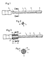
- a vibration damper 10 is now provided on the shaft 3 and surrounding it in the vicinity of its end at the location of its reception in the sleeve 2.
- This consists of an outer sleeve 11 and a damping body 12.
- the sleeve 11 can be made of sheet metal, aluminum or plastic; the damping body consists, for example, of highly elastic, light metal with a firm consistency similar to rubber or rubber. The elasticity is about 50-60 Shore.
- the vibration damper 10 is arranged near the sleeve 2; in the case of longer tools, the vibration damper 10 is arranged somewhat further forward on the shaft. The optimal location must be determined by trying it out.
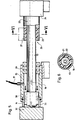
- the vibration damper is shown in a deep drilling tool for the BTA method.
- the deep drilling tool is formed by a shaft 13, on the end of which the drilling head 14 is applied.
- the coolant and lubricant are now supplied via a line 31 and a coolant supply apparatus 15, specifically along the outer circumference of the tube 13 and via the grooves 30 to the drilling site.
- the removal of the coolant and lubricant from the drilling site, including the swarf produced during drilling, then takes place via the channel 16 inside the pipe 13.
- This so-called BTA method is used for larger diameters, since higher torques than those described above Single-lip drilling methods with such tools are possible.
- the coolant supply apparatus 15 is sealed off from the workpiece 32 with the aid of a drill bushing 33; the sealing with respect to the tube 13 takes place with the aid of a stuffing box 34.
- the tube 13 is firmly connected to a clamping element 23, which is then firmly received in the chuck 24 of a drilling spindle.
- the vibration damper 22 is arranged between the coolant supply apparatus 15 and the tensioning element 23. It is also formed in that the space between a metallic sleeve 21 and the tube 13 is filled by an elastic damping body 22.
- the following dimensions resulted: for a drilling depth of 800 mm in workpiece 32 and a drilling diameter of 45 mm, a sleeve with a diameter of 70 mm and a length of 300 mm was used.
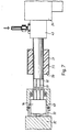
- the drill head is fastened to a double tube, which is formed by the outer tube 50 and the inner tube 51.
- the coolant and lubricant is supplied to the drilling point via the connecting piece 43 and from there via the space between the outer pipe 50 and the inner pipe 51 and is discharged from the drilling point via the inner pipe 51.
- the drill bush 33 for guiding the drill head 14 when drilling is pressed against the workpiece 32 by a drill bush holder 40.
- the drilling spindle is designated 24.
- the vibration damper 20 sits anywhere between drill bushings 33 (or drill bush holder 40) on the one hand and connecting piece 43 on the other hand.
- the outer diameter of the vibration damper should be equal to the diameter of the drill pipe plus approximately 55 mm.
- the length of the vibration damper depends on the drilling diameter. For drilling diameters of up to 70 mm, for example, a dimension of 350-400 mm was chosen as the length for the vibration damper. With drilling diameters of more than 70 mm, the length of the vibration damper was satisfactorily 500 mm.
Landscapes
- Engineering & Computer Science (AREA)
- Mechanical Engineering (AREA)
- Auxiliary Devices For Machine Tools (AREA)
- Drilling Tools (AREA)
- Drilling And Boring (AREA)
- Perforating, Stamping-Out Or Severing By Means Other Than Cutting (AREA)
- Percussive Tools And Related Accessories (AREA)
Claims (5)
Priority Applications (1)
| Application Number | Priority Date | Filing Date | Title |
|---|---|---|---|
| AT83101345T ATE28990T1 (de) | 1982-03-18 | 1983-02-12 | Tiefbohrwerkzeug. |
Applications Claiming Priority (2)
| Application Number | Priority Date | Filing Date | Title |
|---|---|---|---|
| DE3209985A DE3209985C2 (de) | 1982-03-18 | 1982-03-18 | Tiefbohrwerkzeug |
| DE3209985 | 1982-03-18 |
Publications (3)
| Publication Number | Publication Date |
|---|---|
| EP0090929A2 EP0090929A2 (fr) | 1983-10-12 |
| EP0090929A3 EP0090929A3 (en) | 1985-05-22 |
| EP0090929B1 true EP0090929B1 (fr) | 1987-08-19 |
Family
ID=6158661
Family Applications (1)
| Application Number | Title | Priority Date | Filing Date |
|---|---|---|---|
| EP83101345A Expired EP0090929B1 (fr) | 1982-03-18 | 1983-02-12 | Outil à forer des trous profonds |
Country Status (3)
| Country | Link |
|---|---|
| EP (1) | EP0090929B1 (fr) |
| AT (1) | ATE28990T1 (fr) |
| DE (2) | DE3209985C2 (fr) |
Cited By (3)
| Publication number | Priority date | Publication date | Assignee | Title |
|---|---|---|---|---|
| US8118520B2 (en) | 2003-02-24 | 2012-02-21 | Airbus Deutschland Gmbh | Drilling device with displacement dependent spring and/or damper |
| RU182839U1 (ru) * | 2018-03-30 | 2018-09-04 | Акционерное общество "Свердловский инструментальный завод" | Гаситель колебаний |
| DE102020006093A1 (de) | 2020-10-06 | 2022-04-07 | Jürgen Flad | Tiefbohrwerkzeug doppelwandig |
Families Citing this family (11)
| Publication number | Priority date | Publication date | Assignee | Title |
|---|---|---|---|---|
| DE3725014A1 (de) * | 1987-07-29 | 1989-02-09 | Wohlenberg Kg H | Werkzeug fuer tiefliegende innenbearbeitung hohler werkstuecke |
| NO307649B1 (no) * | 1995-09-21 | 2000-05-08 | Teeness As | Støyfjernende adapter for skjæreverktøy |
| US5975816A (en) * | 1997-07-09 | 1999-11-02 | Cook; Harold D. | Harmonic dampener for rotary tool holder |
| SE518390C2 (sv) * | 2000-06-20 | 2002-10-01 | Sandvik Ab | Borrverktyg försett med dämpelement avsett för hålborrning i metalliska material |
| SE522081C2 (sv) * | 2000-12-06 | 2004-01-13 | Sandvik Ab | Verktyg för bearbetning i metalliska material |
| JP2005145041A (ja) * | 2003-10-23 | 2005-06-09 | Ishihara Kikai Kogyo Kk | ノンコアタイプビット、ノンコアドリル装置およびその冷却水給排水方法 |
| CN102350534B (zh) * | 2011-09-21 | 2013-03-27 | 哈尔滨汽轮机厂有限责任公司 | 130t镗床加工汽轮机转子末级轮槽用过渡套 |
| DE102013004582A1 (de) * | 2013-03-18 | 2014-09-18 | Komet Group Gmbh | Spanabhebendes Werkzeug |
| EP3231544B1 (fr) | 2016-04-15 | 2020-08-26 | WFL Millturn Technologies GmbH & Co. KG | Éjecteur-outil à forer des trous profonds |
| CN105889398B (zh) * | 2016-06-03 | 2018-08-10 | 中北大学 | 一种带有减振功能的深孔加工输油器 |
| DE102018002639B3 (de) | 2018-03-30 | 2019-08-08 | Jürgen Flad | Tiefbohrlünette und Verfahren zum Wechseln eines Bohrwerkzeugs |
Family Cites Families (4)
| Publication number | Priority date | Publication date | Assignee | Title |
|---|---|---|---|---|
| US2641940A (en) * | 1949-08-09 | 1953-06-16 | White Dan | Special boring bar |
| DE1219312B (de) * | 1961-03-18 | 1966-06-16 | Werner Kniehahn Dr Ing | Vorrichtung zur Daempfung von Torsionsschwingungen an Fraesspindeln |
| US3230833A (en) * | 1965-02-08 | 1966-01-25 | Norval E Shurtliff | Tool holder |
| CH592489A5 (en) * | 1975-06-10 | 1977-10-31 | Sig Schweiz Industrieges | Deep drilling vibration damper - has elastomer shell of specified dimensions clamped to drill stem near shank |
-
1982
- 1982-03-18 DE DE3209985A patent/DE3209985C2/de not_active Expired
-
1983
- 1983-02-12 EP EP83101345A patent/EP0090929B1/fr not_active Expired
- 1983-02-12 DE DE8383101345T patent/DE3373066D1/de not_active Expired
- 1983-02-12 AT AT83101345T patent/ATE28990T1/de not_active IP Right Cessation
Cited By (4)
| Publication number | Priority date | Publication date | Assignee | Title |
|---|---|---|---|---|
| US8118520B2 (en) | 2003-02-24 | 2012-02-21 | Airbus Deutschland Gmbh | Drilling device with displacement dependent spring and/or damper |
| RU182839U1 (ru) * | 2018-03-30 | 2018-09-04 | Акционерное общество "Свердловский инструментальный завод" | Гаситель колебаний |
| DE102020006093A1 (de) | 2020-10-06 | 2022-04-07 | Jürgen Flad | Tiefbohrwerkzeug doppelwandig |
| DE102020006093B4 (de) | 2020-10-06 | 2023-08-17 | Jürgen Flad | Tiefbohrwerkzeug doppelwandig |
Also Published As
| Publication number | Publication date |
|---|---|
| DE3209985C2 (de) | 1986-07-10 |
| ATE28990T1 (de) | 1987-09-15 |
| DE3209985A1 (de) | 1983-11-17 |
| EP0090929A2 (fr) | 1983-10-12 |
| DE3373066D1 (en) | 1987-09-24 |
| EP0090929A3 (en) | 1985-05-22 |
Similar Documents
| Publication | Publication Date | Title |
|---|---|---|
| EP0090929B1 (fr) | Outil à forer des trous profonds | |
| DE3339211C2 (fr) | ||
| DE102010006796B4 (de) | Verfahren zur Herstellung eines Bohrers, sowie Bohrer | |
| DE60105247T2 (de) | Drehtischvorrichtung | |
| DE10218875A1 (de) | Werkzeug zum Senken, Entgraten und Ausspindeln von Bohrungen | |
| DE3132450A1 (de) | Bohrhammer mit fuehrungszylinder fuer das schlagwerk | |
| DD279199A5 (de) | Vorrichtung zum herstellen von innengewinden | |
| WO2004054771A1 (fr) | Outil de perçage comprenant des elements coupants abrasifs, et machine de perçage entrainant ledit outil | |
| EP0764490B1 (fr) | Pointeau de centrage | |
| DE3345800A1 (de) | Vorrichtung zum herstellen und bearbeiten von zahnraedern | |
| DE2156153A1 (de) | Spindelanordnung fuer werkzeugmaschinen | |
| DE2512794A1 (de) | Gewindeschneid- und senkeinrichtung zum gewindeschneiden und plansenken von gewindeanschluessen | |
| CH400066A (de) | Werkzeug zur Bearbeitung von Metall | |
| DE102017212053A1 (de) | Rotationswerkzeug sowie Verfahren zur Herstellung eines Rotationswerkzeugs | |
| DE112021008186T5 (de) | Bohrer | |
| DE7808006U1 (de) | Holzbohrer | |
| AT306482B (de) | Tieflochkernbohrverfahren | |
| EP0099107A1 (fr) | Tarands | |
| DE3243693A1 (de) | Dornhonwerkzeug | |
| EP4427870A1 (fr) | Outil d'ébarbage inverse | |
| DE3331118C2 (de) | Bohrspindel für eine Glasbohrmaschine, mit am werkstückseitigen Ende angeordnetem Bohrer sowie Senker | |
| DE3525516A1 (de) | Vorrichtung zum verstellen eines rotierenden werkzeugs, insbesondere einer bohrstange | |
| AT154092B (de) | Vorrichtung zum Bohren und Bearbeiten von Planflächen, insbesondere auf Feinbohrwerken. | |
| DE102022116885A1 (de) | Abgestuftes hohlrad | |
| DE10144197C1 (de) | Rotor für eine Exzenterschneckenpumpe |
Legal Events
| Date | Code | Title | Description |
|---|---|---|---|
| PUAI | Public reference made under article 153(3) epc to a published international application that has entered the european phase |
Free format text: ORIGINAL CODE: 0009012 |
|
| AK | Designated contracting states |
Designated state(s): AT BE CH DE FR GB IT LI LU NL SE |
|
| PUAL | Search report despatched |
Free format text: ORIGINAL CODE: 0009013 |
|
| AK | Designated contracting states |
Designated state(s): AT BE CH DE FR GB IT LI LU NL SE |
|
| 17P | Request for examination filed |
Effective date: 19850508 |
|
| RAP1 | Party data changed (applicant data changed or rights of an application transferred) |
Owner name: TBT TIEFBOHRTECHNIK GMBH UND CO. KG. |
|
| 17Q | First examination report despatched |
Effective date: 19860429 |
|
| GRAA | (expected) grant |
Free format text: ORIGINAL CODE: 0009210 |
|
| AK | Designated contracting states |
Kind code of ref document: B1 Designated state(s): AT BE CH DE FR GB IT LI LU NL SE |
|
| REF | Corresponds to: |
Ref document number: 28990 Country of ref document: AT Date of ref document: 19870915 Kind code of ref document: T |
|
| ITF | It: translation for a ep patent filed | ||
| REF | Corresponds to: |
Ref document number: 3373066 Country of ref document: DE Date of ref document: 19870924 |
|
| ET | Fr: translation filed | ||
| PG25 | Lapsed in a contracting state [announced via postgrant information from national office to epo] |
Ref country code: LU Free format text: LAPSE BECAUSE OF NON-PAYMENT OF DUE FEES Effective date: 19880229 |
|
| PLBE | No opposition filed within time limit |
Free format text: ORIGINAL CODE: 0009261 |
|
| STAA | Information on the status of an ep patent application or granted ep patent |
Free format text: STATUS: NO OPPOSITION FILED WITHIN TIME LIMIT |
|
| 26N | No opposition filed | ||
| PG25 | Lapsed in a contracting state [announced via postgrant information from national office to epo] |
Ref country code: GB Effective date: 19890212 Ref country code: AT Effective date: 19890212 |
|
| PG25 | Lapsed in a contracting state [announced via postgrant information from national office to epo] |
Ref country code: SE Effective date: 19890213 |
|
| PG25 | Lapsed in a contracting state [announced via postgrant information from national office to epo] |
Ref country code: LI Effective date: 19890228 Ref country code: CH Effective date: 19890228 Ref country code: BE Effective date: 19890228 |
|
| BERE | Be: lapsed |
Owner name: TBT TIEFBOHRTECHNIK G.M.B.H. UND CO. K.G. Effective date: 19890228 |
|
| PG25 | Lapsed in a contracting state [announced via postgrant information from national office to epo] |
Ref country code: NL Effective date: 19890901 |
|
| NLV4 | Nl: lapsed or anulled due to non-payment of the annual fee | ||
| GBPC | Gb: european patent ceased through non-payment of renewal fee | ||
| PG25 | Lapsed in a contracting state [announced via postgrant information from national office to epo] |
Ref country code: FR Free format text: LAPSE BECAUSE OF NON-PAYMENT OF DUE FEES Effective date: 19891027 |
|
| REG | Reference to a national code |
Ref country code: CH Ref legal event code: PL |
|
| PG25 | Lapsed in a contracting state [announced via postgrant information from national office to epo] |
Ref country code: DE Effective date: 19891101 |
|
| REG | Reference to a national code |
Ref country code: FR Ref legal event code: ST |
|
| EUG | Se: european patent has lapsed |
Ref document number: 83101345.3 Effective date: 19900118 |