EP0090973A1 - Procédé de fabrication d'alliages à couches multiples - Google Patents
Procédé de fabrication d'alliages à couches multiples Download PDFInfo
- Publication number
- EP0090973A1 EP0090973A1 EP83102606A EP83102606A EP0090973A1 EP 0090973 A1 EP0090973 A1 EP 0090973A1 EP 83102606 A EP83102606 A EP 83102606A EP 83102606 A EP83102606 A EP 83102606A EP 0090973 A1 EP0090973 A1 EP 0090973A1
- Authority
- EP
- European Patent Office
- Prior art keywords
- metal
- molten metal
- layer
- alloy
- roller
- Prior art date
- Legal status (The legal status is an assumption and is not a legal conclusion. Google has not performed a legal analysis and makes no representation as to the accuracy of the status listed.)
- Granted
Links
- 238000000034 method Methods 0.000 title claims abstract description 22
- 239000000956 alloy Substances 0.000 title abstract description 62
- 229910045601 alloy Inorganic materials 0.000 title abstract description 60
- 229910052751 metal Inorganic materials 0.000 claims abstract description 87
- 239000002184 metal Substances 0.000 claims abstract description 87
- 229910000808 amorphous metal alloy Inorganic materials 0.000 claims abstract description 22
- 150000002739 metals Chemical class 0.000 claims description 15
- 238000001816 cooling Methods 0.000 claims description 12
- 239000005300 metallic glass Substances 0.000 claims description 9
- 238000002844 melting Methods 0.000 claims description 7
- 230000008018 melting Effects 0.000 claims description 7
- 238000004519 manufacturing process Methods 0.000 abstract description 11
- 239000002131 composite material Substances 0.000 abstract description 7
- 238000010791 quenching Methods 0.000 abstract 2
- 230000000171 quenching effect Effects 0.000 abstract 1
- 239000010410 layer Substances 0.000 description 72
- 239000000203 mixture Substances 0.000 description 6
- 229910000889 permalloy Inorganic materials 0.000 description 6
- 238000005452 bending Methods 0.000 description 5
- 238000012360 testing method Methods 0.000 description 5
- XKRFYHLGVUSROY-UHFFFAOYSA-N Argon Chemical compound [Ar] XKRFYHLGVUSROY-UHFFFAOYSA-N 0.000 description 4
- 239000007789 gas Substances 0.000 description 4
- 238000000926 separation method Methods 0.000 description 4
- 230000006698 induction Effects 0.000 description 3
- 239000000463 material Substances 0.000 description 3
- 238000001612 separation test Methods 0.000 description 3
- 229910052786 argon Inorganic materials 0.000 description 2
- DMFGNRRURHSENX-UHFFFAOYSA-N beryllium copper Chemical compound [Be].[Cu] DMFGNRRURHSENX-UHFFFAOYSA-N 0.000 description 2
- 238000010438 heat treatment Methods 0.000 description 2
- 239000002994 raw material Substances 0.000 description 2
- RYGMFSIKBFXOCR-UHFFFAOYSA-N Copper Chemical compound [Cu] RYGMFSIKBFXOCR-UHFFFAOYSA-N 0.000 description 1
- VYPSYNLAJGMNEJ-UHFFFAOYSA-N Silicium dioxide Chemical compound O=[Si]=O VYPSYNLAJGMNEJ-UHFFFAOYSA-N 0.000 description 1
- 229910000831 Steel Inorganic materials 0.000 description 1
- 238000005253 cladding Methods 0.000 description 1
- 230000000052 comparative effect Effects 0.000 description 1
- 229910052802 copper Inorganic materials 0.000 description 1
- 239000010949 copper Substances 0.000 description 1
- 238000004070 electrodeposition Methods 0.000 description 1
- 239000003822 epoxy resin Substances 0.000 description 1
- 238000005242 forging Methods 0.000 description 1
- 238000005098 hot rolling Methods 0.000 description 1
- 239000011261 inert gas Substances 0.000 description 1
- 238000005304 joining Methods 0.000 description 1
- 239000007788 liquid Substances 0.000 description 1
- 239000000696 magnetic material Substances 0.000 description 1
- 239000000155 melt Substances 0.000 description 1
- 238000010310 metallurgical process Methods 0.000 description 1
- 229910000510 noble metal Inorganic materials 0.000 description 1
- 238000007747 plating Methods 0.000 description 1
- 229920000647 polyepoxide Polymers 0.000 description 1
- 238000003825 pressing Methods 0.000 description 1
- 239000000047 product Substances 0.000 description 1
- 238000005096 rolling process Methods 0.000 description 1
- 239000011265 semifinished product Substances 0.000 description 1
- 239000002356 single layer Substances 0.000 description 1
- 238000009751 slip forming Methods 0.000 description 1
- 238000007711 solidification Methods 0.000 description 1
- 230000008023 solidification Effects 0.000 description 1
- 239000010959 steel Substances 0.000 description 1
- 238000007738 vacuum evaporation Methods 0.000 description 1
- 238000003466 welding Methods 0.000 description 1
Images
Classifications
-
- C—CHEMISTRY; METALLURGY
- C22—METALLURGY; FERROUS OR NON-FERROUS ALLOYS; TREATMENT OF ALLOYS OR NON-FERROUS METALS
- C22C—ALLOYS
- C22C45/00—Amorphous alloys
-
- B—PERFORMING OPERATIONS; TRANSPORTING
- B22—CASTING; POWDER METALLURGY
- B22D—CASTING OF METALS; CASTING OF OTHER SUBSTANCES BY THE SAME PROCESSES OR DEVICES
- B22D11/00—Continuous casting of metals, i.e. casting in indefinite lengths
- B22D11/007—Continuous casting of metals, i.e. casting in indefinite lengths of composite ingots, i.e. two or more molten metals of different compositions being used to integrally cast the ingots
-
- B—PERFORMING OPERATIONS; TRANSPORTING
- B22—CASTING; POWDER METALLURGY
- B22D—CASTING OF METALS; CASTING OF OTHER SUBSTANCES BY THE SAME PROCESSES OR DEVICES
- B22D11/00—Continuous casting of metals, i.e. casting in indefinite lengths
- B22D11/06—Continuous casting of metals, i.e. casting in indefinite lengths into moulds with travelling walls, e.g. with rolls, plates, belts, caterpillars
-
- B—PERFORMING OPERATIONS; TRANSPORTING
- B22—CASTING; POWDER METALLURGY
- B22D—CASTING OF METALS; CASTING OF OTHER SUBSTANCES BY THE SAME PROCESSES OR DEVICES
- B22D19/00—Casting in, on, or around objects which form part of the product
- B22D19/14—Casting in, on, or around objects which form part of the product the objects being filamentary or particulate in form
-
- B—PERFORMING OPERATIONS; TRANSPORTING
- B23—MACHINE TOOLS; METAL-WORKING NOT OTHERWISE PROVIDED FOR
- B23K—SOLDERING OR UNSOLDERING; WELDING; CLADDING OR PLATING BY SOLDERING OR WELDING; CUTTING BY APPLYING HEAT LOCALLY, e.g. FLAME CUTTING; WORKING BY LASER BEAM
- B23K20/00—Non-electric welding by applying impact or other pressure, with or without the application of heat, e.g. cladding or plating
- B23K20/04—Non-electric welding by applying impact or other pressure, with or without the application of heat, e.g. cladding or plating by means of a rolling mill
-
- B—PERFORMING OPERATIONS; TRANSPORTING
- B23—MACHINE TOOLS; METAL-WORKING NOT OTHERWISE PROVIDED FOR
- B23P—METAL-WORKING NOT OTHERWISE PROVIDED FOR; COMBINED OPERATIONS; UNIVERSAL MACHINE TOOLS
- B23P15/00—Making specific metal objects by operations not covered by a single other subclass or a group in this subclass
Definitions
- the present invention relates to a process for producing a multi-layered amorphous alloy having at least one layer of amorphous alloy, by ejecting from a nozzle a first molten metal on a roller rotating at a high speed or on a metal belt driven by the roller, and rotating the ejected metal with the roller for rapid cooling.
- multi-layer alloys are laminated bodies of different metals (to include alloys hereinafter) are known in various fields, for such applications as bimetals with two metals having different heat expansion ratios; cladding material consisting of beryllium copper which is excellent in mechanical strength, and a layer of a noble metal which is excellent in contact characteristics; magnetic wires consisting of beryllium copper and Permalloy (trade name); superconductive wires consisting of copper and a superconductive body; composite magnetic materials used in electrical switching machines; leads used in self-holding type lead switches and so on.
- a method has recently proposed by JA-A-53 106 634 according to which different kinds of molten metals are ejected on each of a pair of revolving rollers, and they are joined and adhered by the rollers for manufacturing a multi-layer amorphous alloy.
- the distance between the nozzles for ejecting the two, different kinds of metals must be made extremely small, obstructing the design, limiting the adhering conditions, and providing an impractical solution to the problem.
- the joining of the two metal layers is performed only between a pair of rollers, so that the adhering time is short and the adhesion between the obtained layers of the multi-layer alloy is disadvantageously low.
- a method to increase the thickness of metal strips which were made by causing molten metal to impinge in a stream upon the surface of a cooled rotating body is known from GB-A-15 548 AD 1913. These thicker strips are produced by causing a second stream of molten metal to impinge upon the strip produced in the aforementioned manner, and the resulting thickened strips could be further thickened by similarly applying a further stream of molten metal. This method, however, only describes the production of strips made of one material.
- each of the layers is formed on an own moving chill surface before the layers are brought together.
- the corresponding device therefore needs a plurality of rollers for producing the single layers.
- the present invention has been made in consideratjon of this prior art and has for its object to provide a process for producing a multi-layered amorphous alloy in which the adhesion is inproved, the feeding positions of the molten metals can be freely chosen without any problems, and at least one layer of amorphous alloy is included.
- the present invention therefore provides a process for producing a milti-layered amorphous alloy as defined in the beginning which is characterized in that two molten metal layers are formed on the rotating roller or belt by ejecting from a second nozzle a second molten metal different from said first metal on said first molten metal for rapid cooling.
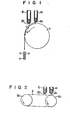
- FIG. 1 A device for carrying out the method of the present invention is shown in Fig. 1.
- a first nozzle 2a and a second nozzle 2b are disposed at the lower ends of a first tubular container 1a and a second tubular container 1b of quartz glass tubes, respectively, for example, for holding two different kinds of raw material metals A and B molten by high frequenzy induction melting.
- a roller 3 Below these first and second nozzles 2a and 2b is disposed a roller 3.
- the molten metal A melted by the first tubular container 1a is ejected through the first nozzle 2a onto the roller 3 by the pressure of an inert gas.
- the ejected molten metal A is rapidly cooled by contacting the roller 3 rotating at a high speed and forms a lower layer consisting of amorphous metal A.
- the molten metal B melted by the second tubular container 1b is ejected on the lower layer of the amorphous metal A through the second nozzle 2a to form an upper layer of amorphous metal B.
- the two layers of metals thus laminated are rapidly cooled to provide a two-layer amorphous alloy 4 of excellent adhesion.
- the layer was a layer of an amorphous metal, it may alternatively be a crystalline metal layer.
- the upper and lower layers must not mix with each other.
- the temperature T 1 of the lower layer of the amorphous metal A when the molten metal B of the upper layer is ejected on it must satisfy inequality (1) or (2) described below:
- T 1 is lower than Ts in both the cases described above, a multi-layer alloy of greater adhesion may be obtained when T 1 is as close to Ts as possible.
- T 1 may be calculated according to the Newton cooling equation as shown below: where T B : roller temperature (C°)
- the times for ejecting the lower layer metal A and the upper layer metal B from the nozzles are determined from the above-mentioned temperature conditions, and the locations for ejecting the lower layer metal A and the upper layer metal B on the roller are determined from each time.
- the ejecting location is defined by the length L of the arc from the contact point between the roller and a vertical line.
- the ejecting location L may be represented as follows:
- the temperature of the molten metal A ejected from the first nozzle 2a is lower than the solidifying temperature, but before completed solidification occurs, the molten metal B is ejected from the nozzle 2b.
- the respective molten metals A and B do not mix together between the two layers, so that a multi-layer amorphous alloy which is not mixed but sufficiently dispersed and greatly improved in adhesion may be obtained.
- the error in the positioning between the metal layers may be easily prevented.
- a device was used in which the molten metals A and B were supplied to the roller.
- a device may alternatively be used in which a metal belt 6 is driven by a pair or rotary rollers 5a and 5b, the same tubular containers 1a and 1b as those of the device shown in Fig. 1 are disposed above the metal belt 6, and the molten metals are ejected from the nozzles 2a and 2b.
- the roller diameter may be made smaller for ejecting the molten metal on the metal belt 6 so that the distance between the tubular containers la and 1b may be sufficient and the arrangement of these containers may become easy.
- the arrangement of the nozzles perpendicular to the belt which is the cooling body becomes easy, contact between the molten metals and the cooling body becomes good, and the cooling efficiency is improved so that the manufacture of the multi-layer alloy including amorphous metal becomes easy.
- a multi-layer amorphous alloy was manufactured with a device as shown in Fig. 1.
- the first tubular container 1a and the second tubular container 1b held 10g each of Co 75 Si 10 B 15 and Ni 75 Si 10 B 15 respectively, prepared in advance by high frequency induction melting.
- This alloy strip was embedded in a cylinder of epoxy resin 1 inch in diameter and was polished as a mirror surface.
- the joined surface was analyzeid with an X-ray microanalyzer.
- the Co 75 Si 10 B 15 alloy and the Ni 75 Si 10 B 15 alloy were divided with a sharp boundary in the direction of the thickness.
- the ribbon-shaped alloy strip was found to consist of two layers of different alloys. Both surfaces of the ribbon-shaped alloy strip were examined by X-ray diffractiometry, and they were both found to be amorphous.
- the section of the ribbon-shaped alloy strip was analyzed with an X-ray microanalyzer in a similar manner as in Example 1.
- the joined surface between the Pd 83.5 Si 16.5 layer and the Fe 75 Si 10 B 15 layer was sharp.
- the X-ray diffractiometry revealed that the two amorphous metal layers in the direction of the thickness were present.
- the separation test was performed as in the Example 1, and no separation was observed in a bending test of 180 degrees.
- the temperature of the Fe 75 Si 10 B 10 alloy on the point of the roller 3 corresponding to L 2 50 mm, that is, where the Pd 83.5 Si 16.5 alloy and the Fe 75 Si 10 B 15 overlapped, was 950°C. This was higher than the crystallizing temperature of 540°C and was lower than the solidifying temperature of 1,100°C.
- the two layer amorphous alloy consists of an amorphous alloy (upper layer) and a crystalline alloy (lower layer).
- the size of the nozzles 2a and 2b was 12 x 0.5 mm , the pressure of argon gas was 0.4 atm, and the rotational speed of the rollers was 3,00 rpm.
- the obtained ribbon-shaped alloy strip was about 12 mminwidth and about 55 ⁇ m in thickness.
- the temperature of the Permalloy at the point on the roller 3 corresponding to L 2 50 mm, that is, where the Pd 80 Si 20 alloy and the Permalloy overlapped, was 1,200°C. This was higher than 2/3 of the melting point, or 930°C, and was lower than the solidifying point of 1,350°C.
- the molten Pd 83.5 Si 16.5 alloy at 1,000°C and the molten Fe 75 S i 10 B 15 alloy at 1,200°C were ejected on the belt at positions corresponding to immediately above the roller 5a and 20 mm away from it, respectively.
- the amount of the molten alloys ejected was 10g in each case.
- the gas pressure was 0.5 atm.
- the nozzle diameter was 0.4 mm and the roller diamter was 100 mm.
- the rotational speed of the rollers was 3,000 rpm.
- the shape of the obtained thin strip was that of a ribbon of 1.3 mm width and 70 ⁇ m thickness.
- the section of the ribbon-shaped alloy strip was analyzed with an X-ray microanalyzer in a manner similar to Example 1.
- the boundary between the Pd 83.5 Si 16.5 layer and the Fe 75 Si 10 B 15 layer was sharp, and the alloys were found to be composite alloys of two layers. Both surfaces of the rippon-shaped alloy strip were examined by X-ray diffractiometry and both were found to be amorphous. The separation test was performed with a bending test of 180 degress in a manner similar to Example 1. The boundary was slightly separated. However, no separation was observed when it was wound on a rod of 5 mm diameter. Thus, it was found that the composite alloy presents no problems in actual use.
- the temperature of the Fe 75 Si 10 B 15 alloy at the point where the Pd 83.5 Si 16.5 alloy and the Fe 75 Si 10 B 15 overlapped was 950°C in this embodiment. This was higher than the crystallizing temperature (540°C) and was lower than the solidifying temperature (1,100°C).
- This alloy was examined with an X-ray microanalyzer and the layers was found to be separated. The alloys easily separted when a bending test of 180 degrees was performed.
- more than three nozzles may be disposed above the roller for manufacturing a multi-layer alloy of three layers or more.
- the process of the present invention for producing a multi-layered alloy having at least one amorphous layer is applicable to the production of various composite alloy materials such as high-sensitivity bimetals, superconductive wires, contact spring composite alloys, latching relays having two-stepped magnetic hysteresis, and high fidelty magnetic heads.
Landscapes
- Engineering & Computer Science (AREA)
- Mechanical Engineering (AREA)
- Chemical & Material Sciences (AREA)
- Materials Engineering (AREA)
- Metallurgy (AREA)
- Organic Chemistry (AREA)
- Continuous Casting (AREA)
Applications Claiming Priority (2)
| Application Number | Priority Date | Filing Date | Title |
|---|---|---|---|
| JP52100/79U | 1979-04-20 | ||
| JP5210079U JPS614440Y2 (fr) | 1979-04-20 | 1979-04-20 |
Related Parent Applications (1)
| Application Number | Title | Priority Date | Filing Date |
|---|---|---|---|
| EP80900783.4 Division | 1980-11-04 |
Publications (2)
| Publication Number | Publication Date |
|---|---|
| EP0090973A1 true EP0090973A1 (fr) | 1983-10-12 |
| EP0090973B1 EP0090973B1 (fr) | 1986-07-23 |
Family
ID=12905419
Family Applications (2)
| Application Number | Title | Priority Date | Filing Date |
|---|---|---|---|
| EP19830102606 Expired EP0090973B1 (fr) | 1979-04-20 | 1980-04-21 | Procédé de fabrication d'alliages à couches multiples |
| EP19800900783 Expired EP0027473B1 (fr) | 1979-04-20 | 1980-11-04 | Procede de production d'un alliage multicouches |
Family Applications After (1)
| Application Number | Title | Priority Date | Filing Date |
|---|---|---|---|
| EP19800900783 Expired EP0027473B1 (fr) | 1979-04-20 | 1980-11-04 | Procede de production d'un alliage multicouches |
Country Status (4)
| Country | Link |
|---|---|
| EP (2) | EP0090973B1 (fr) |
| JP (1) | JPS614440Y2 (fr) |
| DE (2) | DE3071673D1 (fr) |
| WO (1) | WO1980002242A1 (fr) |
Cited By (4)
| Publication number | Priority date | Publication date | Assignee | Title |
|---|---|---|---|---|
| GB2225740A (en) * | 1988-11-19 | 1990-06-13 | Glyco Metall Werke | Continuous casting of alloys containing immiscible components, for manufacture of slide elements for bearings |
| WO1993023187A1 (fr) * | 1992-05-18 | 1993-11-25 | Feichtinger, Ilse, H. | Procede et dispositif pour la fabrication de rubans et de pieces composees en metal |
| EP0640419A1 (fr) * | 1993-08-23 | 1995-03-01 | Mitsui Petrochemical Industries, Ltd. | Procédé pour fabrication de bandes métalliques amorphes |
| WO2009027281A1 (fr) * | 2007-08-24 | 2009-03-05 | Leibniz-Institut Für Festkörper- Und Werkstoffforschung Dresden E.V. | Couches amorphes et procédé de fabrication en continu desdites couches |
Families Citing this family (7)
| Publication number | Priority date | Publication date | Assignee | Title |
|---|---|---|---|---|
| DE3106607C2 (de) * | 1981-02-23 | 1987-08-20 | Fr. Kammerer GmbH, 7530 Pforzheim | Plattierverfahren |
| JPS60121049A (ja) * | 1983-12-02 | 1985-06-28 | Nippon Steel Corp | 金属線材の製造方法 |
| AU600391B2 (en) * | 1987-10-27 | 1990-08-09 | John Lysaght (Australia) Limited | Production of coated metal strip |
| JPH08236365A (ja) * | 1995-02-27 | 1996-09-13 | Nippon Signal Co Ltd:The | 平板状トランス |
| FR2840177B1 (fr) * | 2002-05-30 | 2004-09-10 | Seb Sa | Surface de cuisson facile a nettoyer et article electromenager comportant une telle surface |
| JP2008025020A (ja) * | 2006-06-20 | 2008-02-07 | Tohoku Univ | 非結晶合金バルク或いは非結晶合金と一般結晶金属の複合合金バルクの製造方法 |
| CN107321812B (zh) * | 2017-08-20 | 2023-05-30 | 徐卓辉 | 一种相拼组合结构复合金属片的制备方法及其复合金属片 |
Citations (4)
| Publication number | Priority date | Publication date | Assignee | Title |
|---|---|---|---|---|
| GB191315548A (en) * | 1913-07-05 | 1914-07-02 | Edward Halford Strange | Improvements in, and Apparatus for, the Production of Metal Strips, or Ribbons. |
| US3295173A (en) * | 1964-03-23 | 1967-01-03 | New York Wire Company | Casting machine for clad metal bars |
| US3971123A (en) * | 1973-03-05 | 1976-07-27 | Olsson International Inc. | Process of solidifying molten metal |
| GB2003772A (en) * | 1977-09-12 | 1979-03-21 | Sony Corp | Methods of and apparatus for manufacturing amorphous alloys |
Family Cites Families (3)
| Publication number | Priority date | Publication date | Assignee | Title |
|---|---|---|---|---|
| US3295174A (en) * | 1965-03-09 | 1967-01-03 | New York Wire Company | Casting machine for clad metal bars |
| JPS6040946B2 (ja) * | 1977-03-02 | 1985-09-13 | 株式会社日立製作所 | 複合非晶質テ−プの製造方法 |
| JPS586603Y2 (ja) * | 1977-11-24 | 1983-02-04 | 株式会社東芝 | 複合非晶質金属の製造装置 |
-
1979
- 1979-04-20 JP JP5210079U patent/JPS614440Y2/ja not_active Expired
-
1980
- 1980-04-21 DE DE8383102606T patent/DE3071673D1/de not_active Expired
- 1980-04-21 EP EP19830102606 patent/EP0090973B1/fr not_active Expired
- 1980-04-21 WO PCT/JP1980/000080 patent/WO1980002242A1/fr not_active Ceased
- 1980-04-21 DE DE8080900783T patent/DE3066735D1/de not_active Expired
- 1980-11-04 EP EP19800900783 patent/EP0027473B1/fr not_active Expired
Patent Citations (4)
| Publication number | Priority date | Publication date | Assignee | Title |
|---|---|---|---|---|
| GB191315548A (en) * | 1913-07-05 | 1914-07-02 | Edward Halford Strange | Improvements in, and Apparatus for, the Production of Metal Strips, or Ribbons. |
| US3295173A (en) * | 1964-03-23 | 1967-01-03 | New York Wire Company | Casting machine for clad metal bars |
| US3971123A (en) * | 1973-03-05 | 1976-07-27 | Olsson International Inc. | Process of solidifying molten metal |
| GB2003772A (en) * | 1977-09-12 | 1979-03-21 | Sony Corp | Methods of and apparatus for manufacturing amorphous alloys |
Cited By (7)
| Publication number | Priority date | Publication date | Assignee | Title |
|---|---|---|---|---|
| GB2225740A (en) * | 1988-11-19 | 1990-06-13 | Glyco Metall Werke | Continuous casting of alloys containing immiscible components, for manufacture of slide elements for bearings |
| GB2225740B (en) * | 1988-11-19 | 1993-05-19 | Glyco Metall Werke | A method and a device for the manufacture of laminar material for slide elements |
| WO1993023187A1 (fr) * | 1992-05-18 | 1993-11-25 | Feichtinger, Ilse, H. | Procede et dispositif pour la fabrication de rubans et de pieces composees en metal |
| US5573056A (en) * | 1992-05-18 | 1996-11-12 | Ilse H. Feichtinger | Process and device for producing metal strip and laminates |
| EP0640419A1 (fr) * | 1993-08-23 | 1995-03-01 | Mitsui Petrochemical Industries, Ltd. | Procédé pour fabrication de bandes métalliques amorphes |
| US5647921A (en) * | 1993-08-23 | 1997-07-15 | Mitsui Petrochemical Industries, Ltd. | Process for producing and amorphous alloy resin |
| WO2009027281A1 (fr) * | 2007-08-24 | 2009-03-05 | Leibniz-Institut Für Festkörper- Und Werkstoffforschung Dresden E.V. | Couches amorphes et procédé de fabrication en continu desdites couches |
Also Published As
| Publication number | Publication date |
|---|---|
| JPS55154662U (fr) | 1980-11-07 |
| JPS614440Y2 (fr) | 1986-02-10 |
| DE3071673D1 (en) | 1986-08-28 |
| WO1980002242A1 (fr) | 1980-10-30 |
| EP0027473A1 (fr) | 1981-04-29 |
| DE3066735D1 (en) | 1984-04-05 |
| EP0027473A4 (fr) | 1982-01-08 |
| EP0090973B1 (fr) | 1986-07-23 |
| EP0027473B1 (fr) | 1984-02-29 |
Similar Documents
| Publication | Publication Date | Title |
|---|---|---|
| EP0039169B1 (fr) | Filaments de métal amorphe et procédé pour leur fabrication | |
| US5301742A (en) | Amorphous alloy strip having a large thickness | |
| CN103320783B (zh) | 金属玻璃叠层体、其制造方法及其应用 | |
| EP0090973A1 (fr) | Procédé de fabrication d'alliages à couches multiples | |
| US4257830A (en) | Method of manufacturing a thin ribbon of magnetic material | |
| US3881542A (en) | Method of continuous casting metal filament on interior groove of chill roll | |
| US4650618A (en) | Method for producing strip-like or foil-like products | |
| US4428416A (en) | Method of manufacturing a multi-layer amorphous alloy | |
| US4806721A (en) | Wire electrode for wire-cut electrical discharge machining | |
| CA1160423A (fr) | Methode et dispositif de coulee en coquille d'une bande, la surface de la coquille etant faite de chrome | |
| US4839487A (en) | Wire electrode for wire-cut electrical discharge machining | |
| EP0035037A1 (fr) | Fine bande microcristalline pour materiau magnetique de haute permeabilite magnetique | |
| GB2158746A (en) | Apparatus and process for rolling spin cast strip | |
| US4702302A (en) | Method of making thin alloy wire | |
| Inomata et al. | Fabrication of an Amorphous Composite Alloy | |
| JPS586602Y2 (ja) | 多層非晶質合金の製造装置 | |
| JPS63303662A (ja) | 多層急冷薄帯の製造方法 | |
| EP0148306A2 (fr) | Procédé de fabrication d'une bande à partir d'un alliage | |
| JPS5818998Y2 (ja) | 多層非晶質合金の製造装置 | |
| JPS6040946B2 (ja) | 複合非晶質テ−プの製造方法 | |
| JPS5950956A (ja) | 結晶質金属薄帯の製造装置 | |
| JPS6112984B2 (fr) | ||
| JPH11170006A (ja) | アモルファス金属連続体の製造方法及びアモルファス金属の連続体へのコーティング方法とその製造装置 | |
| JPH06285595A (ja) | 多層非晶質合金薄帯の製造方法 | |
| JPS6027482A (ja) | 非晶質金属薄帯を金属にクラツドする方法 |
Legal Events
| Date | Code | Title | Description |
|---|---|---|---|
| PUAI | Public reference made under article 153(3) epc to a published international application that has entered the european phase |
Free format text: ORIGINAL CODE: 0009012 |
|
| 17P | Request for examination filed |
Effective date: 19830317 |
|
| AC | Divisional application: reference to earlier application |
Ref document number: 27473 Country of ref document: EP |
|
| AK | Designated contracting states |
Designated state(s): CH DE FR LI NL |
|
| RAP1 | Party data changed (applicant data changed or rights of an application transferred) |
Owner name: KABUSHIKI KAISHA TOSHIBA |
|
| GRAA | (expected) grant |
Free format text: ORIGINAL CODE: 0009210 |
|
| AC | Divisional application: reference to earlier application |
Ref document number: 27473 Country of ref document: EP |
|
| AK | Designated contracting states |
Kind code of ref document: B1 Designated state(s): CH DE FR LI NL |
|
| ET | Fr: translation filed | ||
| REF | Corresponds to: |
Ref document number: 3071673 Country of ref document: DE Date of ref document: 19860828 |
|
| PLBE | No opposition filed within time limit |
Free format text: ORIGINAL CODE: 0009261 |
|
| STAA | Information on the status of an ep patent application or granted ep patent |
Free format text: STATUS: NO OPPOSITION FILED WITHIN TIME LIMIT |
|
| 26N | No opposition filed | ||
| PGFP | Annual fee paid to national office [announced via postgrant information from national office to epo] |
Ref country code: FR Payment date: 19910426 Year of fee payment: 12 |
|
| PGFP | Annual fee paid to national office [announced via postgrant information from national office to epo] |
Ref country code: NL Payment date: 19910430 Year of fee payment: 12 |
|
| PGFP | Annual fee paid to national office [announced via postgrant information from national office to epo] |
Ref country code: CH Payment date: 19910507 Year of fee payment: 12 |
|
| PG25 | Lapsed in a contracting state [announced via postgrant information from national office to epo] |
Ref country code: LI Effective date: 19920430 Ref country code: CH Effective date: 19920430 |
|
| PGFP | Annual fee paid to national office [announced via postgrant information from national office to epo] |
Ref country code: DE Payment date: 19920521 Year of fee payment: 13 |
|
| PG25 | Lapsed in a contracting state [announced via postgrant information from national office to epo] |
Ref country code: NL Effective date: 19921101 |
|
| NLV4 | Nl: lapsed or anulled due to non-payment of the annual fee | ||
| PG25 | Lapsed in a contracting state [announced via postgrant information from national office to epo] |
Ref country code: FR Effective date: 19921230 |
|
| REG | Reference to a national code |
Ref country code: CH Ref legal event code: PL |
|
| REG | Reference to a national code |
Ref country code: FR Ref legal event code: ST |
|
| PG25 | Lapsed in a contracting state [announced via postgrant information from national office to epo] |
Ref country code: DE Effective date: 19940101 |