EP0090989A2 - Optique électronique du canon à électrons d'un tube-image couleur - Google Patents
Optique électronique du canon à électrons d'un tube-image couleur Download PDFInfo
- Publication number
- EP0090989A2 EP0090989A2 EP83102719A EP83102719A EP0090989A2 EP 0090989 A2 EP0090989 A2 EP 0090989A2 EP 83102719 A EP83102719 A EP 83102719A EP 83102719 A EP83102719 A EP 83102719A EP 0090989 A2 EP0090989 A2 EP 0090989A2
- Authority
- EP
- European Patent Office
- Prior art keywords
- electron
- parts
- grid
- electron beams
- shows
- Prior art date
- Legal status (The legal status is an assumption and is not a legal conclusion. Google has not performed a legal analysis and makes no representation as to the accuracy of the status listed.)
- Granted
Links
Images




Classifications
-
- H—ELECTRICITY
- H01—ELECTRIC ELEMENTS
- H01J—ELECTRIC DISCHARGE TUBES OR DISCHARGE LAMPS
- H01J29/00—Details of cathode-ray tubes or of electron-beam tubes of the types covered by group H01J31/00
- H01J29/46—Arrangements of electrodes and associated parts for generating or controlling the ray or beam, e.g. electron-optical arrangement
- H01J29/48—Electron guns
- H01J29/50—Electron guns two or more guns in a single vacuum space, e.g. for plural-ray tube
- H01J29/503—Three or more guns, the axes of which lay in a common plane
Definitions
- the invention relates to electron optics according to the preamble of patent claim 1.
- the electron beam generator systems consisted of identical rotationally symmetrical electrodes for each electron beam arranged next to one another. Later, in the so-called “unitized gun", in whose electrode structure the individual electrodes are combined, adjacent, rotationally symmetrical electrodes of the same function were combined to form a common electrode for all beams.
- Such electrodes are asymmetrical, so that they represent a different environment for external and central beams. It is therefore customary to reduce these differences in grating 3 and grating 4, which usually form the electrodes of the main focusing lens, by means of an individual ring provided for each of the three electron beams.
- the three rings are encased in a pot-shaped shell formed electrode parts attached side by side.
- the rotational symmetry is thus approximately present in the interior of these electrodes for the individual electron beams, but when entering and exiting the area of the rings, the center and outside beams have different environments.
- the shape of the electrostatic focusing field is not completely rotationally symmetrical and this to a different degree for center and outside beams.
- the object of the invention is to eliminate the differences in the focusing fields for center and outside beams in the context of an electron-optical improvement of the electrode structure in the electrodes of an electron beam generator system which form the electrostatic focusing lens. This is done by the measures specified in the characterizing part of claim 1.
- Advantageous embodiments of the invention are contained in claims 2 to 6.
- the invention is based on the basic idea that the unequal action of the electron optics on the center and outside beam can be eliminated more thoroughly by introducing complementary asymmetries with the help of free parameters, that is to say in a compensatory manner, than can be done by measures to expand and supplement the symmetry in the electrode structure would. It has been found that such improvements in the properties of the focusing lens result if the rotational symmetry of the electrostatic field acting on the electron beams in the focusing electrode is left in a certain manner and to a certain degree.
- twist is understood to mean the angle between the horizontal line and the lines on the screen written by the three electron beams in the case of horizontal deflection by the magnetic field of the deflection yoke.
- the reduction in the twist by widening the rings in the direction of the vertical deflection can be explained in that the positional tolerances of the electron beams then become less pronounced in the direction of the larger EL-lip axis. Differences in system components also have a weaker effect on the focus voltage.
- the sharpness voltage is understood to be the voltage against the ground potential at the "grating 3", at which the relevant beam is focused on the screen. With the combined electrodes of a "unitized gun", the "grid 2" voltage can no longer be set individually for each beam, which is why high demands must be placed on the equality of the focusing fields.
- Another possibility for simplifying the electrode on the "grating 4" side of the focusing lens, which usually carries the field shapers (shunts and enhancers) used to compensate for the magnetic deflection field, according to one embodiment of the invention consists in that parts of the electrode itself are made of soft magnetic Materials exist so that the soft magnetic field formers welded onto the outer surface of the electrodes are completely or partially unnecessary. This brings a further simplification in the manufacture of the electron gun system. The elec- trode with field former then no longer consists of eight but five, in the cheapest case even only three parts.
- FIGS. 1a to 1e A known electron gun system is shown in FIGS. 1a to 1e.
- 5 aLs "Grid 3" and 6 are usually referred to as “Grid 4".
- "Grid 4" (6) has a very different electrical potential compared to "Grid 3" (5), so that between 5 and 6 an electrostatic focusing lens is formed.
- 1b shows a top view of the "grid 4" (6), the field shapers 7 and 8 (shunts 7 and enhancers 8).
- These field-forming means have the effect that the magnetic deflection field of a deflection unit attached to the tube holder acts equally on the three electron beams passing through the openings 9.
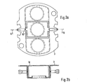
- FIG. 2a two identical parts 10 are fastened in the pot-shaped casing 3.
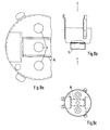
- the height of this part 10 is selected according to the depth of the pot embossed in part 3. This height of the parts can, as shown in FIGS. 5b and 6b, also be variable.
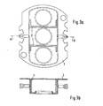
- FIG. 3a there are also two identical parts 11, which, however, are attached with their flanges on the side of the outer beams.
- FIGS. 4a, b and 5a, b show exemplary embodiments with only one part 12 or 13, while FIG. 6a, b shows an example with two identical, but asymmetrical parts 14.
- the parts 10... 14 are fastened in the cup-shaped casing 3.
- An equivalent possibility of attachment is that the parts 10 ... 14 are attached to a circuit board 1 (see also Fig. 1a), which is attached to the pot-shaped casing.
- a circuit board 1 see also Fig. 1a
- Other constructive variants are possible, it being essential that the part or parts in the pot-shaped casing with their surfaces running parallel to the wall surfaces of the pot are arranged in such a way that the three electron beams in the pot are shielded from one another.
- the exact dimensions and shape of the TeiLe take into account test and calculation results.
- FIG. 7 shows the prior art with respect to the grating 4.
- the known three identical parts 2 are attached to the so-called convergence pot.
- the field formers made of magnetic material are also on the convergence pot, but on the other side of the pot base. 7 with two rings around the passage openings of the outer rays, which are called shunts.
- Strips 8, which are known as enhancers, are arranged on both sides of the passage opening of the central jet.
- Fig. 7a is the front view in the direction x
- Fig. 7c shows the view from the direction z.
- the partial section in FIG. 7b shows how the parts 2
- the three parts 2 replaced by one or two parts 10 ... 14, but these parts are also designed in such a way that they affect the function of the field former, namely the effect of the deflecting fat on the deflecting unit to match all three rays, evenly.
- Figures 8 and 9 give two exemplary embodiments.
- the parts 15 and 16 are at least partially made of magnetic material.
- these parts 15, 16 have, in comparison to parts 10 to 14, flange-like, additional surfaces by which they are supplemented in such a way that they can assume the function of field formation.
- Dimensions and shape are also determined by calculation and experiment depending on the conditions of the electrode structure.
- FIGS. Further design options arise if the comprehensive Part 3 is also included in the optimization.
- the parts e.g. the parts 15 and 16 in FIGS. 8 and 9, in ferromagnetic material, they still succeed in transferring the function of the field shapers 7 and 8.
Landscapes
- Video Image Reproduction Devices For Color Tv Systems (AREA)
- Electron Beam Exposure (AREA)
Applications Claiming Priority (2)
| Application Number | Priority Date | Filing Date | Title |
|---|---|---|---|
| DE3212248 | 1982-04-02 | ||
| DE19823212248 DE3212248A1 (de) | 1982-04-02 | 1982-04-02 | Elektronenoptik des elektronenstrahlerzeugersystems einer farbbildroehre |
Publications (3)
| Publication Number | Publication Date |
|---|---|
| EP0090989A2 true EP0090989A2 (fr) | 1983-10-12 |
| EP0090989A3 EP0090989A3 (en) | 1984-09-12 |
| EP0090989B1 EP0090989B1 (fr) | 1988-07-06 |
Family
ID=6160034
Family Applications (1)
| Application Number | Title | Priority Date | Filing Date |
|---|---|---|---|
| EP83102719A Expired EP0090989B1 (fr) | 1982-04-02 | 1983-03-18 | Optique électronique du canon à électrons d'un tube-image couleur |
Country Status (5)
| Country | Link |
|---|---|
| US (1) | US4682073A (fr) |
| EP (1) | EP0090989B1 (fr) |
| JP (1) | JPS58184243A (fr) |
| CA (1) | CA1222276A (fr) |
| DE (2) | DE3212248A1 (fr) |
Families Citing this family (4)
| Publication number | Priority date | Publication date | Assignee | Title |
|---|---|---|---|---|
| NL8402303A (nl) * | 1984-07-20 | 1986-02-17 | Philips Nv | Kleurenbeeldbuis. |
| JP2661024B2 (ja) * | 1986-12-27 | 1997-10-08 | ソニー株式会社 | 陰極線管 |
| TW392190B (en) * | 1998-05-11 | 2000-06-01 | Koninkl Philips Electronics Nv | Cathode ray tube comprising an electron gun |
| KR100596229B1 (ko) * | 1998-09-29 | 2006-09-20 | 엘지전자 주식회사 | 컬러 음극선관 전자총 |
Family Cites Families (12)
| Publication number | Priority date | Publication date | Assignee | Title |
|---|---|---|---|---|
| GB1195598A (en) * | 1967-01-14 | 1970-06-17 | Sony Corp | Cathode Ray Tube |
| US3928785A (en) * | 1971-11-23 | 1975-12-23 | Adrian W Standaart | Single gun, multi-screen, multi-beam, multi-color cathode ray tube |
| US3840765A (en) * | 1972-09-26 | 1974-10-08 | Tokyo Shibaura Electric Co | Shielding member between only the control and side beams in a color cathode ray tube |
| US3866080A (en) * | 1973-08-08 | 1975-02-11 | Rca Corp | Inline electron gun having magnetically permeable plates for enhancing convergence of electron beams |
| JPS5251863A (en) * | 1975-10-22 | 1977-04-26 | Mitsubishi Electric Corp | Electronic gun for color picture tube |
| US4142131A (en) * | 1975-11-12 | 1979-02-27 | Hitachi, Ltd. | Color picture tube |
| JPS5292473A (en) * | 1976-01-30 | 1977-08-03 | Mitsubishi Electric Corp | Main lens electric field forming method of inline type 3 beam electron gun |
| NL7802129A (nl) * | 1978-02-27 | 1979-08-29 | Philips Nv | Inrichting voor het weergeven van gekleurde beelden. |
| US4225804A (en) * | 1978-04-22 | 1980-09-30 | Gte Sylvania N.V. | Cathode ray tube coma correction device |
| US4396862A (en) * | 1978-05-01 | 1983-08-02 | Rca Corporation | Color picture tube with means for affecting magnetic deflection fields in electron gun area |
| US4208610A (en) * | 1978-06-09 | 1980-06-17 | Zenith Radio Corporation | Television picture tubes having an electron gun with aperture electrode shielding means |
| US4275332A (en) * | 1978-07-25 | 1981-06-23 | Matsushita Electronics Corporation | In-line electron gun |
-
1982
- 1982-04-02 DE DE19823212248 patent/DE3212248A1/de not_active Withdrawn
-
1983
- 1983-03-18 EP EP83102719A patent/EP0090989B1/fr not_active Expired
- 1983-03-18 DE DE8383102719T patent/DE3377311D1/de not_active Expired
- 1983-03-31 CA CA000425030A patent/CA1222276A/fr not_active Expired
- 1983-04-01 JP JP58055361A patent/JPS58184243A/ja active Pending
-
1986
- 1986-11-06 US US06/928,663 patent/US4682073A/en not_active Expired - Fee Related
Also Published As
| Publication number | Publication date |
|---|---|
| DE3377311D1 (en) | 1988-08-11 |
| EP0090989B1 (fr) | 1988-07-06 |
| US4682073A (en) | 1987-07-21 |
| EP0090989A3 (en) | 1984-09-12 |
| CA1222276A (fr) | 1987-05-26 |
| JPS58184243A (ja) | 1983-10-27 |
| DE3212248A1 (de) | 1983-10-06 |
Similar Documents
| Publication | Publication Date | Title |
|---|---|---|
| DE2608463C3 (de) | Inline-Farbbildröhre | |
| DE2938769C2 (de) | In-line-Elektronenstrahl-Erzeugungssystem | |
| EP0218920B1 (fr) | Filtre d'énergie électronique de type Oméga | |
| DE2850411C2 (de) | Elektronenstrahlerzeugungssystem in einer Kathodenstrahlröhre | |
| EP1995758B1 (fr) | Monochromateur et source de faisceau de particules chargées dotée d'un tel monochromateur | |
| DD201744A5 (de) | Farbbildroehre mit verbessertem inline-elektronenstrahlsystem mit ausgedehnter fokuslinse | |
| DE3107634A1 (de) | Farbbildroehre mit aberrationsarmer strahlfokussierungslinse | |
| DE3225632C2 (de) | Inline-Elektronenstrahlsystem | |
| DE69311775T2 (de) | Elektronenstrahlablenklinse für farbkathodenstrahlröhre | |
| DE69013183T2 (de) | Farbbildröhrensystem mit reduziertem Fleckwachstum. | |
| DE69510968T2 (de) | Farbkathodenstrahlröhre | |
| DE68918405T2 (de) | Elektronenerzeugungssystem mit Mehrschrittfokussierung für Kathodenstrahlröhre. | |
| DE3923345A1 (de) | Ionenimplantationssystem | |
| EP0090989A2 (fr) | Optique électronique du canon à électrons d'un tube-image couleur | |
| DE69506080T2 (de) | Bildanzeigevorrichtung mit elektronenkanone, und elektronenkanone zur verwendung in einer solchen vorrichtung | |
| DE3614429C2 (fr) | ||
| DD238473A5 (de) | Schlitzmaskenelektronenkanone fuer katodenstrahlroehren | |
| DE4431335B4 (de) | Elektronenkanone für eine Farbbildröhre | |
| DE3216039C2 (de) | Elektronenstrahl-Erzeugungssystem einer Kathodenstrahlröhre | |
| DE2513281C2 (de) | Mehrstrahl-Elektronenstrahlerzeugungssystem für Farbkathodenstrahlröhren | |
| AT393924B (de) | Farbbildroehre mit ablenkjoch | |
| DE3043048C2 (fr) | ||
| EP0138264A2 (fr) | Tube-image couleurs | |
| DE3123301C2 (de) | Vorrichtung zum Einstellen von Elektronenstrahlen einer Kathodenstrahlröhre | |
| DE60300792T2 (de) | Inline-Elektronenkanone und Farbbildröhre mit selbiger |
Legal Events
| Date | Code | Title | Description |
|---|---|---|---|
| PUAI | Public reference made under article 153(3) epc to a published international application that has entered the european phase |
Free format text: ORIGINAL CODE: 0009012 |
|
| AK | Designated contracting states |
Designated state(s): DE FR GB IT NL |
|
| PUAL | Search report despatched |
Free format text: ORIGINAL CODE: 0009013 |
|
| AK | Designated contracting states |
Designated state(s): DE FR GB IT NL |
|
| 17P | Request for examination filed |
Effective date: 19841017 |
|
| RAP1 | Party data changed (applicant data changed or rights of an application transferred) |
Owner name: STANDARD ELEKTRIK LORENZ AKTIENGESELLSCHAFT Owner name: ALCATEL N.V. |
|
| RAP3 | Party data changed (applicant data changed or rights of an application transferred) |
Owner name: STANDARD ELEKTRIK LORENZ AKTIENGESELLSCHAFT Owner name: ALCATEL N.V. |
|
| GRAA | (expected) grant |
Free format text: ORIGINAL CODE: 0009210 |
|
| AK | Designated contracting states |
Kind code of ref document: B1 Designated state(s): DE FR GB IT NL |
|
| ITF | It: translation for a ep patent filed | ||
| GBT | Gb: translation of ep patent filed (gb section 77(6)(a)/1977) | ||
| REF | Corresponds to: |
Ref document number: 3377311 Country of ref document: DE Date of ref document: 19880811 |
|
| ET | Fr: translation filed | ||
| RAP2 | Party data changed (patent owner data changed or rights of a patent transferred) |
Owner name: NOKIA GRAETZ GESELLSCHAFT MIT BESCHRAENKTER HAFTUN |
|
| NLT2 | Nl: modifications (of names), taken from the european patent patent bulletin |
Owner name: NOKIA GRAETZ GESELLSCHAFT MIT BESCHRAENKTER HAFTUN |
|
| REG | Reference to a national code |
Ref country code: FR Ref legal event code: TP |
|
| PG25 | Lapsed in a contracting state [announced via postgrant information from national office to epo] |
Ref country code: GB Effective date: 19890318 |
|
| NLS | Nl: assignments of ep-patents |
Owner name: NOKIA GRAETZ GMBH TE PFORZHEIM, BONDSREPUBLIEK DUI |
|
| PLBE | No opposition filed within time limit |
Free format text: ORIGINAL CODE: 0009261 |
|
| STAA | Information on the status of an ep patent application or granted ep patent |
Free format text: STATUS: NO OPPOSITION FILED WITHIN TIME LIMIT |
|
| 26N | No opposition filed | ||
| PG25 | Lapsed in a contracting state [announced via postgrant information from national office to epo] |
Ref country code: NL Effective date: 19891001 |
|
| GBPC | Gb: european patent ceased through non-payment of renewal fee | ||
| NLV4 | Nl: lapsed or anulled due to non-payment of the annual fee | ||
| PG25 | Lapsed in a contracting state [announced via postgrant information from national office to epo] |
Ref country code: FR Free format text: LAPSE BECAUSE OF NON-PAYMENT OF DUE FEES Effective date: 19891130 |
|
| PG25 | Lapsed in a contracting state [announced via postgrant information from national office to epo] |
Ref country code: DE Effective date: 19891201 |
|
| REG | Reference to a national code |
Ref country code: FR Ref legal event code: ST |