EP0091040A2 - Disjoncteur de protection à courant excessif - Google Patents
Disjoncteur de protection à courant excessif Download PDFInfo
- Publication number
- EP0091040A2 EP0091040A2 EP83103009A EP83103009A EP0091040A2 EP 0091040 A2 EP0091040 A2 EP 0091040A2 EP 83103009 A EP83103009 A EP 83103009A EP 83103009 A EP83103009 A EP 83103009A EP 0091040 A2 EP0091040 A2 EP 0091040A2
- Authority
- EP
- European Patent Office
- Prior art keywords
- lever
- contact
- overcurrent protection
- protection switch
- actuating element
- Prior art date
- Legal status (The legal status is an assumption and is not a legal conclusion. Google has not performed a legal analysis and makes no representation as to the accuracy of the status listed.)
- Granted
Links
Images


Classifications
-
- H—ELECTRICITY
- H01—ELECTRIC ELEMENTS
- H01H—ELECTRIC SWITCHES; RELAYS; SELECTORS; EMERGENCY PROTECTIVE DEVICES
- H01H71/00—Details of the protective switches or relays covered by groups H01H73/00 - H01H83/00
- H01H71/10—Operating or release mechanisms
- H01H71/50—Manual reset mechanisms which may be also used for manual release
- H01H71/52—Manual reset mechanisms which may be also used for manual release actuated by lever
- H01H71/528—Manual reset mechanisms which may be also used for manual release actuated by lever comprising a toggle or collapsible link between handle and contact arm, e.g. sear pin mechanism
-
- H—ELECTRICITY
- H01—ELECTRIC ELEMENTS
- H01H—ELECTRIC SWITCHES; RELAYS; SELECTORS; EMERGENCY PROTECTIVE DEVICES
- H01H2300/00—Orthogonal indexing scheme relating to electric switches, relays, selectors or emergency protective devices covered by H01H
- H01H2300/046—Orthogonal indexing scheme relating to electric switches, relays, selectors or emergency protective devices covered by H01H using snap closing mechanisms
- H01H2300/048—Snap closing by latched movable contact, wherein the movable contact is held in a minimal distance from the fixed contact during first phase of closing sequence in which a closing spring is charged
Definitions
- the invention relates to an overcurrent protection switch with the features of the preamble of claim 1.
- a switch is known from DE-PS 593 512.
- the movement of the actuating element is transmitted to a pivotable contact arm which, together with a contact fixed to the housing, forms the main contact of the switch.
- a restraining stop cooperating with the actuating element ensures that the contact elements close suddenly (momentary activation) when the contact is switched on.
- the known switch has the disadvantage that relatively large masses are firmly coupled to the contact arm when it is switched on and off and thus influence its switching behavior. There is also a risk of false triggering due to fluttering movements of the armature of the magnetic release.
- the invention has for its object to design a switch of the type mentioned in such a way that it has a defined switching behavior with a compact design and uncomplicated handling.
- the contact arm rests in its central region on the retaining stop, which is part of a separate component that is independent of the contact arm, and takes it with it when it snaps into the closed position.
- This makes it possible to dispense with further parts of the switch lock which trigger the yielding closing movement of the restraint stop, which increases the operational reliability of the switch.
- the contact arm can freely move upwards into the open position, as a result of which the inertia of the locking mechanism does not have a negative effect on the switching time.
- a particularly simple and functional way of arranging and guiding the restraint stop teaches claim 2, it being emphasized that the release of the restraint stop is carried out directly and thus in a structurally simple manner by the actuating element itself.
- Claims 4 and 5 ensure that when the switch is switched off or overcurrent tripped, the retaining pawl jumps back into its retaining position.
- the spring exerts a torque on the retaining pawl via the projection, which it engages under, such that when the main contact opens, the retaining pawl securely latches behind the housing projection holding it in the retaining position and simultaneously exerts a system pressure directed against the actuating element.
- the characterizing features of claim 7 ensure that the hinged anchor remains quietly in its rest position and "sticks" to the shunt bend until the force exerted on it by the coil flow is greater than the holding force of the shunt bend. This prevents the armature from fluttering and thus prevents premature tripping if necessary.
- Claim 10 enables the switch lock according to the invention to be used in different switch housings, which simplifies the storage of components.
- Claim 11 is concerned with a special, particularly functional design of the transmission of the axial movement of a push button on the stretching lever.
- Claim 12 enables control of an auxiliary circuit switch known per se.
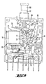
- the key switch (Fig. 2,3,5 to 7)
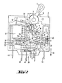
- the switch lock is operated manually via the rocker arm 1. This is rotatably mounted in the two housing halves with its pins 3 on both sides. In the drawing, the lower housing part 2 is shown. A joint 4 is arranged in the inner region of the rocker arm.
- the toggle lever element consisting of the first stretching lever 5 and the second stretching lever 6, is mounted on it, which in turn is rotatably connected by means of the knee joint 7.
- the lower end of the toggle lever element is articulated to the contact arm 9 via the bolt 8.
- the stretching lever 5 is approximately triangular and has a further pivot point 10 in the third corner, in which a latching lever 11 is mounted.
- the latch lever can hook with a catch 12 of the extension lever 6, so that the knee joint 7 becomes stiff.
- the latched knee joint is shown in FIG.
- the force component is aligned so that a left-turning torque is exerted on the rocker arm 1.
- the rocker arm 1 comes to rest in this position.
- the key switch is cocked.
- the force component of the tensioned switch lock is greater than the counterforce of the torsion spring (not shown) on the rocker arm 1.
- the knee joint 7 remains locked.
- the contacts are influenced solely by the rocker arm positions.
- the switch lock is triggered automatically via the magn.-hydr. Trigger 15.
- the hinged armature 16 When there is a corresponding overcurrent, the hinged armature 16 picks up and rotates about the pivot point 17. The arm 18 of the hinged armature 16 presses against the latching lever 11 and moves it upward. The latching between the latch lever 11 and the catch 12 of the extension lever 6 is released and the knee joint 7 collapses. This is caused by the torsion spring 19, which moves the contact arm 9 upwards by its spring force.
- the circle of the magnetic hydraulic release has a magnetic yoke 20 which is provided with a shunt bend 22 connected to the magnetic core 21.
- the yoke In the middle area, the yoke carries lateral tabs in which the parts of the key switch are stored and guided.
- the rest of the magnetic flux goes from the hinged armature 16 to the core 21.
- the hinged armature 16 can be fixed in its rest position more or less long. Only with larger currents does the pulling force between the hinged armature 16 and the core 21 prevail and the hinged armature 16 can tear away from its contact point on the shunt bend 22.
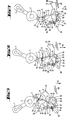
- the retaining pawl 23 is rotatably and displaceably mounted on the bolt 26.
- the retaining pawl 23 is pressed against the bolt 25 by the compression spring 24 (FIG. 5). If the key switch is moved to the switch-on position, the toggle lever element leads the contact arm 9 downwards. This movement is slowed down by the stop 28.
- the bolt 8 moves freely and unhindered in the backdrop 27. This position is shown in FIG. 7. When the rocker arm 1 moves further, the main contact 48 cannot close.
- the stop 28 acts as a fulcrum, so that the contact arm 9 is at its fulcrum 13 means of the bearing groove 57 moves.
- the coupling for manual actuation takes place on the rocker arms 1 by interposing the coupling piece 30.
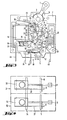
- the parts mentioned are connected to one another by suitable mechanical elements. This is shown in FIG. 1 using a two-pole device consisting of two individual devices (device 31 and device 32).
- the operating lever 42 has two attachment points.
- the stop point 43 is moved downward by the contact arm 9. With it, the stop point 44 moves against the contact spring and causes it to snap.
- the current flows from the connection 45 to the coil of the magnetic hydraulic release 15, from this via a wire to the contact arm 9 and then via the contact pair to the connection 46.
- Quenching plates are arranged in the region of the contacts.
- the arc gases can be blown out via appropriate channels in the housing.
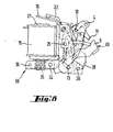
- Fig. 8 again shows the switch lock with magnetic release, which can be used as a prefabricated component in the housing of different dimensions and designs (Fig. 9 and Fig. 10).
- the actuating element is a push-pull button 60 which is axially displaceable in a screw sleeve 61 on the upper side 62 of the housing is arranged. Its inner end 63 interacts via an arm 64 by means of a pin 66 guided in an elongated hole 65 with a pivot lever 67 which converts the axial button movement into a pivoting movement and is pivotably mounted on an axis 68 fixed to the housing and with the first stretching lever 5 via a joint 69 connected is.
- the unit 58 corresponds in function and components to the switch already described.
- Auxiliary contacts 38 are arranged on the lower side of the housing facing away from the actuating element (push-pull button 60) and are actuated via an actuating lever 70 which interacts with the contact side of the contact arm 9.
- the assembly 58 is also used in the exemplary embodiment shown in FIG. 10 of a switch which can be placed on a switch rail, the actuating element also being designed as a rocker arm as in the first exemplary embodiment explained.
- the connection elements 71-74 for the main and auxiliary circuit are in the side area of the housing.
Landscapes
- Breakers (AREA)
Applications Claiming Priority (2)
| Application Number | Priority Date | Filing Date | Title |
|---|---|---|---|
| DE3212474 | 1982-04-03 | ||
| DE3212474A DE3212474C2 (de) | 1982-04-03 | 1982-04-03 | Überstromschutzschalter |
Publications (3)
| Publication Number | Publication Date |
|---|---|
| EP0091040A2 true EP0091040A2 (fr) | 1983-10-12 |
| EP0091040A3 EP0091040A3 (en) | 1985-03-27 |
| EP0091040B1 EP0091040B1 (fr) | 1987-06-03 |
Family
ID=6160177
Family Applications (1)
| Application Number | Title | Priority Date | Filing Date |
|---|---|---|---|
| EP83103009A Expired EP0091040B1 (fr) | 1982-04-03 | 1983-03-26 | Disjoncteur de protection à courant excessif |
Country Status (2)
| Country | Link |
|---|---|
| EP (1) | EP0091040B1 (fr) |
| DE (3) | DE3212474C2 (fr) |
Cited By (7)
| Publication number | Priority date | Publication date | Assignee | Title |
|---|---|---|---|---|
| GB2176659A (en) * | 1985-05-01 | 1986-12-31 | Mitsubishi Electric Corp | Circuit interrupter |
| EP0146528A3 (en) * | 1983-11-28 | 1987-01-21 | Felten & Guilleaume Fabrik Elektrischer Apparate Aktiengesellschaft Schrems-Eugenia Niederosterreich | Switching mechanism for a protective power circuit breaker |
| FR2654253A1 (fr) * | 1989-11-03 | 1991-05-10 | Schupa Elektro Gmbh & Co Kg | Dispositif de fermeture brusque des constacts de leviers mobiles, notamment pour disjoncteur bipolaire de protection contre les courants de fuite. |
| EP0847070A3 (fr) * | 1996-02-06 | 1998-11-04 | Rockwell Automation AG | Disjoncteur de surintensité, en particulier disjoncteur pour moteur |
| EP2688085A1 (fr) * | 2012-07-17 | 2014-01-22 | Abb Ag | Commutateur d'installation électrique |
| EP3767660A1 (fr) * | 2019-07-16 | 2021-01-20 | Eaton Intelligent Power Limited | Dispositif de commutation |
| WO2022028849A1 (fr) * | 2020-08-07 | 2022-02-10 | Siemens Aktiengesellschaft | Mécanisme de commutation à ressort compact indépendant de l'opérateur et dispositif de commutation de protection électromécanique |
Families Citing this family (1)
| Publication number | Priority date | Publication date | Assignee | Title |
|---|---|---|---|---|
| DE102019219314A1 (de) * | 2019-12-11 | 2021-06-17 | Siemens Aktiengesellschaft | Elektrischer Schalter mit einem Verrastmechanismus |
Family Cites Families (9)
| Publication number | Priority date | Publication date | Assignee | Title |
|---|---|---|---|---|
| DE593512C (de) * | 1934-02-27 | Siemens Schuckertwerke Akt Ges | Installationsselbstschalter mit Momenteinschaltung | |
| CH178667A (de) * | 1933-07-04 | 1935-07-31 | Stotz Kontakt Gmbh | Vorrichtung zur Momenteinschaltung an elektrischen Selbstschaltern. |
| DE959291C (de) * | 1950-05-25 | 1957-03-07 | Siemens Ag | Elektromagnetischer UEberstromausloeser fuer Wechselstrom |
| US2700711A (en) * | 1951-12-14 | 1955-01-25 | Heinemann Electric Co | Automatic circuit breaker |
| DE1187722B (de) * | 1960-05-17 | 1965-02-25 | Licentia Gmbh | Selbstschalter mit elektromagnetischen und/oder thermischen Ausloesern |
| US3329912A (en) * | 1965-10-01 | 1967-07-04 | Wood Electric Corp | Multipole circuit breaker with interconnected toggle locks and contact members |
| DE2015624A1 (de) * | 1970-04-02 | 1971-10-21 | Bbc Brown Boveri & Cie | Selbstschalter |
| DE2132738B1 (de) * | 1971-07-01 | 1972-07-06 | Ellenberger & Poensgen | Ein- oder mehrpoliger UEberstromschalter mit thermischer und/oder elektromagnetischer Ausloesung |
| DE2656877A1 (de) * | 1975-12-22 | 1977-07-07 | Mitsubishi Electric Corp | Elektromagnetische vorrichtung, insbesondere ueberstrom-ausloesevorrichtung |
-
1982
- 1982-04-03 DE DE3212474A patent/DE3212474C2/de not_active Expired
- 1982-04-03 DE DE8209597U patent/DE8209597U1/de not_active Expired
-
1983
- 1983-03-26 EP EP83103009A patent/EP0091040B1/fr not_active Expired
- 1983-03-26 DE DE8383103009T patent/DE3371959D1/de not_active Expired
Cited By (10)
| Publication number | Priority date | Publication date | Assignee | Title |
|---|---|---|---|---|
| EP0146528A3 (en) * | 1983-11-28 | 1987-01-21 | Felten & Guilleaume Fabrik Elektrischer Apparate Aktiengesellschaft Schrems-Eugenia Niederosterreich | Switching mechanism for a protective power circuit breaker |
| GB2176659A (en) * | 1985-05-01 | 1986-12-31 | Mitsubishi Electric Corp | Circuit interrupter |
| US4743878A (en) * | 1985-05-01 | 1988-05-10 | Mitsubishi Denki Kabushiki Kaisha | Circuit interrupter |
| GB2176659B (en) * | 1985-05-01 | 1989-05-10 | Mitsubishi Electric Corp | Circuit interrupter |
| FR2654253A1 (fr) * | 1989-11-03 | 1991-05-10 | Schupa Elektro Gmbh & Co Kg | Dispositif de fermeture brusque des constacts de leviers mobiles, notamment pour disjoncteur bipolaire de protection contre les courants de fuite. |
| BE1005375A0 (fr) * | 1989-11-03 | 1993-07-06 | Schupa Elektro Gmbh & Co Kg | Dispositif d'enclenchement brusque d'un levier de contact monte de facon mobile, en particulier pour un commutateur de protection contre des courants de defaut. |
| EP0847070A3 (fr) * | 1996-02-06 | 1998-11-04 | Rockwell Automation AG | Disjoncteur de surintensité, en particulier disjoncteur pour moteur |
| EP2688085A1 (fr) * | 2012-07-17 | 2014-01-22 | Abb Ag | Commutateur d'installation électrique |
| EP3767660A1 (fr) * | 2019-07-16 | 2021-01-20 | Eaton Intelligent Power Limited | Dispositif de commutation |
| WO2022028849A1 (fr) * | 2020-08-07 | 2022-02-10 | Siemens Aktiengesellschaft | Mécanisme de commutation à ressort compact indépendant de l'opérateur et dispositif de commutation de protection électromécanique |
Also Published As
| Publication number | Publication date |
|---|---|
| EP0091040B1 (fr) | 1987-06-03 |
| EP0091040A3 (en) | 1985-03-27 |
| DE8209597U1 (de) | 1986-11-13 |
| DE3212474A1 (de) | 1983-10-13 |
| DE3212474C2 (de) | 1986-02-06 |
| DE3371959D1 (en) | 1987-07-09 |
Similar Documents
| Publication | Publication Date | Title |
|---|---|---|
| DE3520905C2 (fr) | ||
| EP2634787B1 (fr) | Mécanisme de verrouillage d'un disjoncteur | |
| DE2132738B1 (de) | Ein- oder mehrpoliger UEberstromschalter mit thermischer und/oder elektromagnetischer Ausloesung | |
| EP1760748B1 (fr) | Appareil de commutation électrique | |
| EP0892420A2 (fr) | Discontacteur à maximum avec cliquet pour la protection des moteurs | |
| EP0091040B1 (fr) | Disjoncteur de protection à courant excessif | |
| EP1760747B1 (fr) | Disjoncteur électrique | |
| DE3119165C2 (de) | Selbstschalter als Baueinheit aus einem Leitungsschutzschalter sowie Hilfs- und Signalschaltern | |
| DE2115034B2 (de) | Schutzschalter mit ueberstrom-, kurzschluss- und fehlerstromschutz | |
| DE827984C (de) | Selbstschalter | |
| DE4339425B4 (de) | Schaltschloß für einen Fehlerstromschutzschalter | |
| EP1005060B1 (fr) | Déclencheur à manque de tension | |
| DE4122268C2 (fr) | ||
| AT404769B (de) | Leitungsschutzschalter | |
| EP0147629B1 (fr) | Disjoncteur de protection | |
| DE3643511C2 (fr) | ||
| EP0731979B1 (fr) | Interrupteur de securite | |
| DE2904211C2 (de) | Fehlerstromschutzschalter, der an einen Leitungsschutzschalter gekoppelt ist | |
| EP0146528B1 (fr) | Mécanisme de commutation pour disjoncteur de protection de puissance | |
| EP0127784A1 (fr) | Disjoncteur de surintensité | |
| DE598210C (de) | Installationsselbstschalter mit Druckknopfsteuerung und einem senkrecht zur Druckknopfachse beweglichen Kontaktorgan | |
| EP1659604B1 (fr) | Appareil de commutation pour une installation électrique | |
| EP1329923A2 (fr) | Disjoncteur à structure simplifiée | |
| DE3049518C2 (de) | Schloßmechanismus für einen Niederspannungs-Schutzschalter | |
| DE2521341C2 (de) | Mehrpoliger Leitungsschutzschaller |
Legal Events
| Date | Code | Title | Description |
|---|---|---|---|
| PUAI | Public reference made under article 153(3) epc to a published international application that has entered the european phase |
Free format text: ORIGINAL CODE: 0009012 |
|
| AK | Designated contracting states |
Designated state(s): CH DE FR GB IT LI |
|
| ITCL | It: translation for ep claims filed |
Representative=s name: RICCARDI SERGIO & CO. |
|
| EL | Fr: translation of claims filed | ||
| PUAL | Search report despatched |
Free format text: ORIGINAL CODE: 0009013 |
|
| AK | Designated contracting states |
Designated state(s): CH DE FR GB IT LI |
|
| 17P | Request for examination filed |
Effective date: 19850430 |
|
| 17Q | First examination report despatched |
Effective date: 19860319 |
|
| GRAA | (expected) grant |
Free format text: ORIGINAL CODE: 0009210 |
|
| AK | Designated contracting states |
Kind code of ref document: B1 Designated state(s): CH DE FR GB IT LI |
|
| REF | Corresponds to: |
Ref document number: 3371959 Country of ref document: DE Date of ref document: 19870709 |
|
| ET | Fr: translation filed | ||
| ITF | It: translation for a ep patent filed | ||
| PLBE | No opposition filed within time limit |
Free format text: ORIGINAL CODE: 0009261 |
|
| STAA | Information on the status of an ep patent application or granted ep patent |
Free format text: STATUS: NO OPPOSITION FILED WITHIN TIME LIMIT |
|
| 26N | No opposition filed | ||
| ITTA | It: last paid annual fee | ||
| PGFP | Annual fee paid to national office [announced via postgrant information from national office to epo] |
Ref country code: DE Payment date: 19970204 Year of fee payment: 15 |
|
| PGFP | Annual fee paid to national office [announced via postgrant information from national office to epo] |
Ref country code: GB Payment date: 19970305 Year of fee payment: 15 |
|
| PGFP | Annual fee paid to national office [announced via postgrant information from national office to epo] |
Ref country code: FR Payment date: 19970319 Year of fee payment: 15 |
|
| PGFP | Annual fee paid to national office [announced via postgrant information from national office to epo] |
Ref country code: CH Payment date: 19970324 Year of fee payment: 15 |
|
| PG25 | Lapsed in a contracting state [announced via postgrant information from national office to epo] |
Ref country code: GB Free format text: LAPSE BECAUSE OF NON-PAYMENT OF DUE FEES Effective date: 19980326 |
|
| PG25 | Lapsed in a contracting state [announced via postgrant information from national office to epo] |
Ref country code: LI Free format text: LAPSE BECAUSE OF NON-PAYMENT OF DUE FEES Effective date: 19980331 Ref country code: FR Free format text: THE PATENT HAS BEEN ANNULLED BY A DECISION OF A NATIONAL AUTHORITY Effective date: 19980331 Ref country code: CH Free format text: LAPSE BECAUSE OF NON-PAYMENT OF DUE FEES Effective date: 19980331 |
|
| REG | Reference to a national code |
Ref country code: CH Ref legal event code: PL |
|
| GBPC | Gb: european patent ceased through non-payment of renewal fee |
Effective date: 19980326 |
|
| PG25 | Lapsed in a contracting state [announced via postgrant information from national office to epo] |
Ref country code: DE Free format text: LAPSE BECAUSE OF NON-PAYMENT OF DUE FEES Effective date: 19981201 |
|
| REG | Reference to a national code |
Ref country code: FR Ref legal event code: ST |