EP2688085A1 - Commutateur d'installation électrique - Google Patents
Commutateur d'installation électrique Download PDFInfo
- Publication number
- EP2688085A1 EP2688085A1 EP13003499.4A EP13003499A EP2688085A1 EP 2688085 A1 EP2688085 A1 EP 2688085A1 EP 13003499 A EP13003499 A EP 13003499A EP 2688085 A1 EP2688085 A1 EP 2688085A1
- Authority
- EP
- European Patent Office
- Prior art keywords
- holding part
- holding
- contact lever
- switching device
- knob
- Prior art date
- Legal status (The legal status is an assumption and is not a legal conclusion. Google has not performed a legal analysis and makes no representation as to the accuracy of the status listed.)
- Granted
Links
Images

Classifications
-
- H—ELECTRICITY
- H01—ELECTRIC ELEMENTS
- H01H—ELECTRIC SWITCHES; RELAYS; SELECTORS; EMERGENCY PROTECTIVE DEVICES
- H01H71/00—Details of the protective switches or relays covered by groups H01H73/00 - H01H83/00
- H01H71/10—Operating or release mechanisms
- H01H71/50—Manual reset mechanisms which may be also used for manual release
- H01H71/52—Manual reset mechanisms which may be also used for manual release actuated by lever
- H01H71/526—Manual reset mechanisms which may be also used for manual release actuated by lever the lever forming a toggle linkage with a second lever, the free end of which is directly and releasably engageable with a contact structure
-
- H—ELECTRICITY
- H01—ELECTRIC ELEMENTS
- H01H—ELECTRIC SWITCHES; RELAYS; SELECTORS; EMERGENCY PROTECTIVE DEVICES
- H01H71/00—Details of the protective switches or relays covered by groups H01H73/00 - H01H83/00
- H01H71/02—Housings; Casings; Bases; Mountings
- H01H2071/0292—Housing or frames containing grooves or slots for guiding movable parts
-
- H—ELECTRICITY
- H01—ELECTRIC ELEMENTS
- H01H—ELECTRIC SWITCHES; RELAYS; SELECTORS; EMERGENCY PROTECTIVE DEVICES
- H01H2300/00—Orthogonal indexing scheme relating to electric switches, relays, selectors or emergency protective devices covered by H01H
- H01H2300/046—Orthogonal indexing scheme relating to electric switches, relays, selectors or emergency protective devices covered by H01H using snap closing mechanisms
- H01H2300/048—Snap closing by latched movable contact, wherein the movable contact is held in a minimal distance from the fixed contact during first phase of closing sequence in which a closing spring is charged
Definitions
- the invention relates to an electrical service switching device with a rear derailleur with Verklinkungsstelle, with a contact lever which is connected via a tab and a coupling element with a toggle, which is spent in pivoting the switch knob in the switch-on the contact lever with latched Verklinkungsstelle in closed position, means for temporary Holding and subsequent release of the movable contact lever are provided during the switch-on, so that when switching a sudden impact of the contact lever mounted on the movable contact piece is effected on the fixed contact piece, according to the preamble of claim 1.
- a generic installation switching device is in the DE 10 2010 019 033 B1 described.
- the means for temporarily holding the movable contact lever during the switch-on process cause, when these means are released, a sudden impact of the movable contact piece is effected on the fixed contact piece.
- the time of approach of the movable to the fixed contact piece is greatly shortened.
- the switch-on is greatly accelerated at least in the time in which an arc can occur.
- the means for temporarily holding the movable contact lever comprises a holding part, a movable intermediate part and an adjusting lever, wherein the movable intermediate part connects the holding part and the adjusting lever, and wherein between the switching knob and the adjusting lever an operative connection means is provided to move on advancing the Shift knob to bring the lever and thus the holding part in a release position in which the contact lever is released, so that a sudden impact of the contact lever mounted on the movable contact piece is effected on the fixed contact piece.
- the intermediate part is designed resiliently, so that it automatically moves back to its holding position after resetting the switch knob due to the restoring spring force of the resilient intermediate part, and then ready to block the contact lever again at times when the next operation of the switch knob.
- the intermediate part has a metal insert, for example a leaf spring, which is encapsulated by plastic material.
- a metal insert for example a leaf spring
- the preparation of such a holding part with molded thereon intermediate part, which includes a plastic-coated leaf spring is expensive, the part is difficult to handle in its manufacture and during its installation in the service switching device, it can easily bend, which reduces its reliability function.
- the means comprises a holding part and a rigid coupling part, wherein an operative connection means is provided between the switching toggle and the coupling part in order to bring the dome part and thus the holding part into a release position when the switching knob is moved further, in which the contact lever is released, and a resilient return means is provided, which is supported on the one hand on a housing contour and on the other hand on the holding part, so that the holding part is resiliently acted upon in its release position in the direction of a holding position in which the contact lever bears against the holding part.
- the advantage over the solutions known from the prior art is that the holding part no longer has to perform bending or twisting, it is only rigidly moved linearly, and the provision in the holding position is effected by a second, separate component.
- the functions "hold / release” and “reset” are realized in two separate but coupled components. Thus, each of the two components can be constructed easier in itself.
- the holding part is a rigid part, which only has to cope with a linear movement, and the return means may be a known compression spring, which is characterized by ease of assembly and high reliability.
- the holding part is mounted longitudinally displaceable on a housing contour, so that the holding part between its release position and its holding position is linearly movable.
- the storage on a housing contour is simple and with high reliability produced and permanently executable.
- the operative connection means is an engagement surface on an extension of the switch knob. This ensures a direct engagement of the switch knob with the means for temporarily holding the movable contact lever, without interposition of other elements, which simplifies the assembly.
- the coupling part is designed as a rigid bar and formed on the holding part.
- the assembly, consisting of the holding part and the coupling part, can thus be executed as elongated, rigid partially, resulting in a space-saving installation.
- the holding part and the coupling part can be made in one piece from the same material.
- the holding part may consist of a first material and the coupling part of a second material, wherein the assembly of the holding part and the coupling part can be made together in a multi-component injection molding process.
- the first material is an abrasion-resistant material with high temperature resistance, for example a material known under the trade name Ultrason E2010.
- the second material may be a common, simple and stable plastic material, for example a duroplastic.
- FIG. 1a shows a partial insight into the lower part of an open installation switching device according to the invention 1.
- An installation switching device 1, here a circuit breaker is often constructed in the so-called shell construction, so also here. It has a housing, which is composed of two housing half-shells, which are assembled at a circumferential joining edge.
- the one housing half shell is referred to as lower part 101, the other is referred to as upper part.
- the lower part 101 most elements, parts and assemblies of the line circuit breaker are used.
- the in the FIGS. 1a and 2 shown circuit breaker corresponds substantially to that in the DE 10 2008 006 863 A1 is described.
- the DE 10 2008 006 863 A1 Therefore, with respect to the structure and operation of the circuit breaker 1, and with respect to the structure and operation of the switching mechanism of this circuit breaker should be included in the disclosure of the present invention. In the further description of this invention will therefore not be discussed in more detail on the rear derailleur, or only insofar as it is necessary to explain the subject of the present invention. Of course, however, the present invention is not for use with a derailleur as in DE 10 2008 006 863 A1 shown, but rather applicable to all conceivable types of derailleurs in all conceivable types of service switching devices.
- the contact point of the circuit breaker is closed.
- the contact lever 2 with the movable contact piece 7 is pivoted in the clockwise direction, towards the fixed contact piece 7, there is contact between the fixed and the movable contact piece 7, 6, it can flow current.
- the switch knob 5 is in the closed position, its handle is pivoted counterclockwise and is located in the left-facing switch-on.
- the contact force with which the movable presses on the fixed contact piece is applied by a contact pressure spring, which is not shown here, whose function in the mentioned DE 10 2008 006 863 A1 is described.
- the switch knob 5 has a first extension 8, which is arranged opposite the handle.
- the extension 8 is connected via the coupling element (not shown) with the tab 3, for this purpose, 8 holes 8a are provided in the first extension, in which the coupling element, usually a bracket, can intervene.
- FIG. 1 a further an assembly 102 of a magnetic Schlagankersystems whose structure and function is also known in principle.
- narrow side of the impact armature system 102 is attached to a short leg 103, which merges into a 90 ° parallel to the longitudinal extent of the Schlagankersystems 102 bent long leg 104, which forms an arc guide rail to a resulting in a rapid separation of the contact point there arc in to lead an arc quenching device, of which in the FIG. 1a only the holding ribs 105 can be seen, in which the arc-quenching plates (not shown) of such a known in principle arc quenching device are held.
- the fixed contact horn 106 which carries the fixed contact piece 7.
- This means 10 essentially comprises two parts, a holding part 12 and a rigid coupling part thirteenth
- the holding part 12 has a holding part base body 16 with a slot-like recess.
- the slot-like recess has a rectangular longitudinal section contour.
- the holding part 12 is longitudinally displaceably mounted on a housing contour 18, so that the holding part 12 is linearly movable between a lower position, the switch knob 5 facing away, and an upper position, the switch knob 5, is mounted on the housing contour.
- the lower position is the holding position
- the upper position is the release position
- the housing contour 18 is an approximately rectangular projection which is formed on the inside of the housing half shell 101, for example, was produced as a housing contour during injection molding.
- the housing contour 18 is adapted to the slot-like recess in the holding part base body that a tight, yet slidable guide of the holding part is guaranteed.
- the design of the housing contour 18 in interaction with the holding part 12 is designed so that when mounting the holding part 12 can be used with its slot-like recess in the open housing half shell 101 and thereby pushed over the housing contour 18, where it is then held linearly displaceable as described above.
- a holding extension 15 is integrally formed on the holding part base body 16. He has in about an L-shape, the long leg in extension of the holding part base body 16 down, away from the switch knob 5, points, and whose short leg is perpendicular to the plane defined by the holding part base body 16 level and thus in mounted Condition approximately perpendicularly away from the inner surface of the housing half-shell 101 points away.
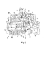
- FIG. 2 it can be seen that in the holding position of the holding part 12 of the contact lever 2 rests with a stop lug 17 on the retaining extension 15 before it comes into contact with the fixed contact piece 7, and thus the contact point is kept open in the holding position of the holding part.
- the coupling part 13 is formed as a rigid beam on the holding part 12, on the holding extension 15 opposite narrow side, so that it extends up to the switch knob 5 out. At its free, upper end, the coupling part 13 carries an L-shaped projecting arm 20, see FIG. 1 b.
- the extension 8 of the switch knob 5 has an engagement surface 11 against which the arm 20 rests in a coupling manner.
- an operative connection means 11 is thus provided in the form of the engagement surface to bring the dome part 13 and thus the holding part 12 in a release position upon further movement of the switch knob 5 from the off.
- an operative connection means 11 is thus provided in the form of the engagement surface to bring the dome part 13 and thus the holding part 12 in a release position upon further movement of the switch knob 5 from the off.
- This further extension serves to support a compression spring 4 on it.
- a resilient return means 4 is given, on the one hand is supported on the holding part 12 and on the other hand on a second housing contour 14, so that the holding part 12 is resiliently acted upon in its release position in the direction of the holding position in which the contact lever bears against the holding part 12.
- the pulling of the holding member 12 upwards into its release position is namely in this way against the restoring force of the compression spring 4.
- the restoring spring force of the compression spring 4 would like to move the holding member 12 back into its holding position.
- FIG. 1a the position is shown in which the contact point is closed, the movable contact piece 6 is pressed against the fixed contact piece 7.
- the holding extension 15 of the holding part 12 is now on top of the stop lug 17. In order to prevent the contact lever in the closed position, that the holding part 12 is pressed by the compression spring 4 further down into its holding position.
- the means 10 may be made in a preferred embodiment as an injection molded part made of plastic.
- the assembly of the holding part 12 and the coupling part 13 is made together in a multi-component injection molding process of a first and a second material.
- the first material is an abrasion-resistant material with high temperature resistance
- the second material is a normal, stable plastic, such as a thermosetting plastic.
- the first material is a high temperature resistant, abrasion-resistant material such as a polysulfone (PSU), polyethersulfone (PES) or polyphenysulfone (PPSU) material, also known under the trade name Ultrason.
- PSU polysulfone
- PES polyethersulfone
- PPSU polyphenysulfone
- the holding part 12 comes to rest in the region of the contact point. There may occur a switching operation due to a forming switching arc to a temporary significant increase in temperature. Therefore, it is advantageous that the holding part 12 is made of an abrasion-resistant material having high temperature resistance.
- the assemblies and components, including the means 10 are inserted into the housing half-shell 101, and the housing bottom and - top are assembled. It is just another, simply constructed component required to realize the jump function of the derailleur.
- the assembly is very simple and suitable to be performed by a production machine at high speed, because the means 10 is inserted only in the upper housing part in the appropriate place. A high functional reliability is given, because the means 10 is only linearly shifted.
Landscapes
- Rotary Switch, Piano Key Switch, And Lever Switch (AREA)
- Tumbler Switches (AREA)
Applications Claiming Priority (1)
| Application Number | Priority Date | Filing Date | Title |
|---|---|---|---|
| DE201210014104 DE102012014104A1 (de) | 2012-07-17 | 2012-07-17 | Elektrisches Installationsschaltgerät |
Publications (2)
| Publication Number | Publication Date |
|---|---|
| EP2688085A1 true EP2688085A1 (fr) | 2014-01-22 |
| EP2688085B1 EP2688085B1 (fr) | 2015-04-08 |
Family
ID=48738742
Family Applications (1)
| Application Number | Title | Priority Date | Filing Date |
|---|---|---|---|
| EP20130003499 Active EP2688085B1 (fr) | 2012-07-17 | 2013-07-11 | Commutateur d'installation électrique |
Country Status (3)
| Country | Link |
|---|---|
| EP (1) | EP2688085B1 (fr) |
| CN (1) | CN203055815U (fr) |
| DE (1) | DE102012014104A1 (fr) |
Citations (6)
| Publication number | Priority date | Publication date | Assignee | Title |
|---|---|---|---|---|
| EP0091040A2 (fr) * | 1982-04-03 | 1983-10-12 | Ellenberger & Poensgen GmbH | Disjoncteur de protection à courant excessif |
| DE4016364A1 (de) * | 1989-06-30 | 1991-01-03 | Siemens Ag | Leitungsschutzschalter mit momenteinschaltung |
| WO2003012812A1 (fr) * | 2001-08-01 | 2003-02-13 | Abb Service S.R.L. | Disjoncteur pour circuit electrique basse tension |
| DE102008006863A1 (de) | 2007-05-23 | 2009-01-22 | Abb Ag | Elektrisches Installationsschaltgerät |
| EP2061059A1 (fr) * | 2007-11-16 | 2009-05-20 | Schneider Electric Industries SAS | Dispositif de commande d'un appareil électrique de coupure, et appareil électrique de coupure le comportant |
| DE102010019033B4 (de) | 2010-05-03 | 2012-02-23 | Abb Ag | Elektrisches Installationsschaltgerät |
-
2012
- 2012-07-17 DE DE201210014104 patent/DE102012014104A1/de not_active Withdrawn
- 2012-08-20 CN CN201220533349.8U patent/CN203055815U/zh not_active Expired - Lifetime
-
2013
- 2013-07-11 EP EP20130003499 patent/EP2688085B1/fr active Active
Patent Citations (6)
| Publication number | Priority date | Publication date | Assignee | Title |
|---|---|---|---|---|
| EP0091040A2 (fr) * | 1982-04-03 | 1983-10-12 | Ellenberger & Poensgen GmbH | Disjoncteur de protection à courant excessif |
| DE4016364A1 (de) * | 1989-06-30 | 1991-01-03 | Siemens Ag | Leitungsschutzschalter mit momenteinschaltung |
| WO2003012812A1 (fr) * | 2001-08-01 | 2003-02-13 | Abb Service S.R.L. | Disjoncteur pour circuit electrique basse tension |
| DE102008006863A1 (de) | 2007-05-23 | 2009-01-22 | Abb Ag | Elektrisches Installationsschaltgerät |
| EP2061059A1 (fr) * | 2007-11-16 | 2009-05-20 | Schneider Electric Industries SAS | Dispositif de commande d'un appareil électrique de coupure, et appareil électrique de coupure le comportant |
| DE102010019033B4 (de) | 2010-05-03 | 2012-02-23 | Abb Ag | Elektrisches Installationsschaltgerät |
Also Published As
| Publication number | Publication date |
|---|---|
| DE102012014104A1 (de) | 2014-02-06 |
| EP2688085B1 (fr) | 2015-04-08 |
| CN203055815U (zh) | 2013-07-10 |
Similar Documents
| Publication | Publication Date | Title |
|---|---|---|
| EP2140521B1 (fr) | Commutateur d'installation comportant un dispositif de borne a ressort de rappel | |
| DE69627973T2 (de) | Hilfsschalter für Ausschalter und entsprechender Ausschalter | |
| EP2329564B1 (fr) | Appareillage de commutation d'installation présentant une connexion serrée sans vis | |
| EP1995754B1 (fr) | Commutateur d'installation électrique | |
| DE102014211549B4 (de) | Feststellvorrichtung für einen Flügel | |
| WO2016079077A1 (fr) | Borne à ressort | |
| DE102008053137A1 (de) | Hebelverbindung | |
| DE60013294T2 (de) | Elektrischer schalter für einen gashahn | |
| DE102010019033B4 (de) | Elektrisches Installationsschaltgerät | |
| EP4189782B1 (fr) | Borne de connexion de conducteur | |
| EP0352679B1 (fr) | Appareillage interrupteur électrique | |
| DE2558942C2 (de) | Schalter mit einem kippbaren Schalthebel | |
| EP2688085B1 (fr) | Commutateur d'installation électrique | |
| WO2010015308A1 (fr) | Appareil de commutation d'installation doté d'une connexion de bornes sans vis | |
| EP2567389B1 (fr) | Disjoncteur d'installation électrique | |
| DE2705330C2 (de) | Elektrischer Schalter, insbesondere Motorschutzschalter | |
| DE202012001641U1 (de) | Elektrischer Lasttrennschalter für Niederspannung | |
| EP3055875A1 (fr) | Appareil de commutation pourvu d'un élément amortisseur pour le système de contact lors d'une mise en circuit brusque | |
| DE102012201677A1 (de) | Elektrisches Schaltgerät, insbesondere Leistungsschalter | |
| EP0371419A2 (fr) | Disjoncteur électrique | |
| EP2437353A1 (fr) | Appareil de commutation d'installation doté d'un dispositif de connexion enfichable | |
| EP2824689B1 (fr) | Déclencheur dynamique et commutateur d'installation électrique doté d'un déclencheur dynamique | |
| DE102013004093B4 (de) | Elektrisches lnstallationsschaltgerät | |
| EP0043406B1 (fr) | Elément interrupteur de protection pour être ajouté à un appareil interrupteur construit comme interrupteur rotatif | |
| DE102009043780A1 (de) | Elektrisches Überlastrelais mit einer schwenkbar gelagerten Wippe |
Legal Events
| Date | Code | Title | Description |
|---|---|---|---|
| PUAI | Public reference made under article 153(3) epc to a published international application that has entered the european phase |
Free format text: ORIGINAL CODE: 0009012 |
|
| AK | Designated contracting states |
Kind code of ref document: A1 Designated state(s): AL AT BE BG CH CY CZ DE DK EE ES FI FR GB GR HR HU IE IS IT LI LT LU LV MC MK MT NL NO PL PT RO RS SE SI SK SM TR |
|
| AX | Request for extension of the european patent |
Extension state: BA ME |
|
| 17P | Request for examination filed |
Effective date: 20140721 |
|
| GRAP | Despatch of communication of intention to grant a patent |
Free format text: ORIGINAL CODE: EPIDOSNIGR1 |
|
| INTG | Intention to grant announced |
Effective date: 20141205 |
|
| RIN1 | Information on inventor provided before grant (corrected) |
Inventor name: DAHMANN, JOACHIM Inventor name: EPPE, KLAUS-PETER Inventor name: HAUCK, DIRK Inventor name: WEBER, RALF Inventor name: MUDERS, ERWIN |
|
| GRAS | Grant fee paid |
Free format text: ORIGINAL CODE: EPIDOSNIGR3 |
|
| GRAP | Despatch of communication of intention to grant a patent |
Free format text: ORIGINAL CODE: EPIDOSNIGR1 |
|
| GRAA | (expected) grant |
Free format text: ORIGINAL CODE: 0009210 |
|
| INTG | Intention to grant announced |
Effective date: 20150216 |
|
| AK | Designated contracting states |
Kind code of ref document: B1 Designated state(s): AL AT BE BG CH CY CZ DE DK EE ES FI FR GB GR HR HU IE IS IT LI LT LU LV MC MK MT NL NO PL PT RO RS SE SI SK SM TR |
|
| REG | Reference to a national code |
Ref country code: GB Ref legal event code: FG4D Free format text: NOT ENGLISH |
|
| REG | Reference to a national code |
Ref country code: CH Ref legal event code: EP |
|
| REG | Reference to a national code |
Ref country code: IE Ref legal event code: FG4D Free format text: LANGUAGE OF EP DOCUMENT: GERMAN |
|
| REG | Reference to a national code |
Ref country code: DE Ref legal event code: R096 Ref document number: 502013000520 Country of ref document: DE Effective date: 20150513 |
|
| REG | Reference to a national code |
Ref country code: AT Ref legal event code: REF Ref document number: 721104 Country of ref document: AT Kind code of ref document: T Effective date: 20150515 |
|
| REG | Reference to a national code |
Ref country code: NL Ref legal event code: VDEP Effective date: 20150408 |
|
| REG | Reference to a national code |
Ref country code: LT Ref legal event code: MG4D |
|
| PG25 | Lapsed in a contracting state [announced via postgrant information from national office to epo] |
Ref country code: NL Free format text: LAPSE BECAUSE OF FAILURE TO SUBMIT A TRANSLATION OF THE DESCRIPTION OR TO PAY THE FEE WITHIN THE PRESCRIBED TIME-LIMIT Effective date: 20150408 |
|
| PG25 | Lapsed in a contracting state [announced via postgrant information from national office to epo] |
Ref country code: PT Free format text: LAPSE BECAUSE OF FAILURE TO SUBMIT A TRANSLATION OF THE DESCRIPTION OR TO PAY THE FEE WITHIN THE PRESCRIBED TIME-LIMIT Effective date: 20150810 Ref country code: NO Free format text: LAPSE BECAUSE OF FAILURE TO SUBMIT A TRANSLATION OF THE DESCRIPTION OR TO PAY THE FEE WITHIN THE PRESCRIBED TIME-LIMIT Effective date: 20150708 Ref country code: FI Free format text: LAPSE BECAUSE OF FAILURE TO SUBMIT A TRANSLATION OF THE DESCRIPTION OR TO PAY THE FEE WITHIN THE PRESCRIBED TIME-LIMIT Effective date: 20150408 Ref country code: HR Free format text: LAPSE BECAUSE OF FAILURE TO SUBMIT A TRANSLATION OF THE DESCRIPTION OR TO PAY THE FEE WITHIN THE PRESCRIBED TIME-LIMIT Effective date: 20150408 Ref country code: LT Free format text: LAPSE BECAUSE OF FAILURE TO SUBMIT A TRANSLATION OF THE DESCRIPTION OR TO PAY THE FEE WITHIN THE PRESCRIBED TIME-LIMIT Effective date: 20150408 Ref country code: ES Free format text: LAPSE BECAUSE OF FAILURE TO SUBMIT A TRANSLATION OF THE DESCRIPTION OR TO PAY THE FEE WITHIN THE PRESCRIBED TIME-LIMIT Effective date: 20150408 |
|
| PG25 | Lapsed in a contracting state [announced via postgrant information from national office to epo] |
Ref country code: RS Free format text: LAPSE BECAUSE OF FAILURE TO SUBMIT A TRANSLATION OF THE DESCRIPTION OR TO PAY THE FEE WITHIN THE PRESCRIBED TIME-LIMIT Effective date: 20150408 Ref country code: IS Free format text: LAPSE BECAUSE OF FAILURE TO SUBMIT A TRANSLATION OF THE DESCRIPTION OR TO PAY THE FEE WITHIN THE PRESCRIBED TIME-LIMIT Effective date: 20150808 Ref country code: LV Free format text: LAPSE BECAUSE OF FAILURE TO SUBMIT A TRANSLATION OF THE DESCRIPTION OR TO PAY THE FEE WITHIN THE PRESCRIBED TIME-LIMIT Effective date: 20150408 Ref country code: GR Free format text: LAPSE BECAUSE OF FAILURE TO SUBMIT A TRANSLATION OF THE DESCRIPTION OR TO PAY THE FEE WITHIN THE PRESCRIBED TIME-LIMIT Effective date: 20150709 |
|
| REG | Reference to a national code |
Ref country code: DE Ref legal event code: R097 Ref document number: 502013000520 Country of ref document: DE |
|
| PG25 | Lapsed in a contracting state [announced via postgrant information from national office to epo] |
Ref country code: DK Free format text: LAPSE BECAUSE OF FAILURE TO SUBMIT A TRANSLATION OF THE DESCRIPTION OR TO PAY THE FEE WITHIN THE PRESCRIBED TIME-LIMIT Effective date: 20150408 Ref country code: EE Free format text: LAPSE BECAUSE OF FAILURE TO SUBMIT A TRANSLATION OF THE DESCRIPTION OR TO PAY THE FEE WITHIN THE PRESCRIBED TIME-LIMIT Effective date: 20150408 |
|
| PLBE | No opposition filed within time limit |
Free format text: ORIGINAL CODE: 0009261 |
|
| STAA | Information on the status of an ep patent application or granted ep patent |
Free format text: STATUS: NO OPPOSITION FILED WITHIN TIME LIMIT |
|
| PG25 | Lapsed in a contracting state [announced via postgrant information from national office to epo] |
Ref country code: SK Free format text: LAPSE BECAUSE OF FAILURE TO SUBMIT A TRANSLATION OF THE DESCRIPTION OR TO PAY THE FEE WITHIN THE PRESCRIBED TIME-LIMIT Effective date: 20150408 Ref country code: RO Free format text: LAPSE BECAUSE OF NON-PAYMENT OF DUE FEES Effective date: 20150408 Ref country code: MC Free format text: LAPSE BECAUSE OF FAILURE TO SUBMIT A TRANSLATION OF THE DESCRIPTION OR TO PAY THE FEE WITHIN THE PRESCRIBED TIME-LIMIT Effective date: 20150408 Ref country code: CZ Free format text: LAPSE BECAUSE OF FAILURE TO SUBMIT A TRANSLATION OF THE DESCRIPTION OR TO PAY THE FEE WITHIN THE PRESCRIBED TIME-LIMIT Effective date: 20150408 Ref country code: PL Free format text: LAPSE BECAUSE OF FAILURE TO SUBMIT A TRANSLATION OF THE DESCRIPTION OR TO PAY THE FEE WITHIN THE PRESCRIBED TIME-LIMIT Effective date: 20150408 |
|
| 26N | No opposition filed |
Effective date: 20160111 |
|
| PG25 | Lapsed in a contracting state [announced via postgrant information from national office to epo] |
Ref country code: LU Free format text: LAPSE BECAUSE OF FAILURE TO SUBMIT A TRANSLATION OF THE DESCRIPTION OR TO PAY THE FEE WITHIN THE PRESCRIBED TIME-LIMIT Effective date: 20150711 |
|
| REG | Reference to a national code |
Ref country code: IE Ref legal event code: MM4A |
|
| PG25 | Lapsed in a contracting state [announced via postgrant information from national office to epo] |
Ref country code: SI Free format text: LAPSE BECAUSE OF FAILURE TO SUBMIT A TRANSLATION OF THE DESCRIPTION OR TO PAY THE FEE WITHIN THE PRESCRIBED TIME-LIMIT Effective date: 20150408 |
|
| REG | Reference to a national code |
Ref country code: FR Ref legal event code: PLFP Year of fee payment: 4 |
|
| PG25 | Lapsed in a contracting state [announced via postgrant information from national office to epo] |
Ref country code: IE Free format text: LAPSE BECAUSE OF NON-PAYMENT OF DUE FEES Effective date: 20150711 |
|
| REG | Reference to a national code |
Ref country code: CH Ref legal event code: PL |
|
| PG25 | Lapsed in a contracting state [announced via postgrant information from national office to epo] |
Ref country code: MT Free format text: LAPSE BECAUSE OF FAILURE TO SUBMIT A TRANSLATION OF THE DESCRIPTION OR TO PAY THE FEE WITHIN THE PRESCRIBED TIME-LIMIT Effective date: 20150408 |
|
| PG25 | Lapsed in a contracting state [announced via postgrant information from national office to epo] |
Ref country code: LI Free format text: LAPSE BECAUSE OF NON-PAYMENT OF DUE FEES Effective date: 20160731 Ref country code: CH Free format text: LAPSE BECAUSE OF NON-PAYMENT OF DUE FEES Effective date: 20160731 |
|
| PG25 | Lapsed in a contracting state [announced via postgrant information from national office to epo] |
Ref country code: BG Free format text: LAPSE BECAUSE OF FAILURE TO SUBMIT A TRANSLATION OF THE DESCRIPTION OR TO PAY THE FEE WITHIN THE PRESCRIBED TIME-LIMIT Effective date: 20150408 Ref country code: HU Free format text: LAPSE BECAUSE OF FAILURE TO SUBMIT A TRANSLATION OF THE DESCRIPTION OR TO PAY THE FEE WITHIN THE PRESCRIBED TIME-LIMIT; INVALID AB INITIO Effective date: 20130711 |
|
| PG25 | Lapsed in a contracting state [announced via postgrant information from national office to epo] |
Ref country code: CY Free format text: LAPSE BECAUSE OF FAILURE TO SUBMIT A TRANSLATION OF THE DESCRIPTION OR TO PAY THE FEE WITHIN THE PRESCRIBED TIME-LIMIT Effective date: 20150408 Ref country code: SE Free format text: LAPSE BECAUSE OF FAILURE TO SUBMIT A TRANSLATION OF THE DESCRIPTION OR TO PAY THE FEE WITHIN THE PRESCRIBED TIME-LIMIT Effective date: 20150408 |
|
| REG | Reference to a national code |
Ref country code: FR Ref legal event code: PLFP Year of fee payment: 5 |
|
| PG25 | Lapsed in a contracting state [announced via postgrant information from national office to epo] |
Ref country code: BE Free format text: LAPSE BECAUSE OF NON-PAYMENT OF DUE FEES Effective date: 20150731 |
|
| GBPC | Gb: european patent ceased through non-payment of renewal fee |
Effective date: 20170711 |
|
| PG25 | Lapsed in a contracting state [announced via postgrant information from national office to epo] |
Ref country code: GB Free format text: LAPSE BECAUSE OF NON-PAYMENT OF DUE FEES Effective date: 20170711 |
|
| PG25 | Lapsed in a contracting state [announced via postgrant information from national office to epo] |
Ref country code: SM Free format text: LAPSE BECAUSE OF FAILURE TO SUBMIT A TRANSLATION OF THE DESCRIPTION OR TO PAY THE FEE WITHIN THE PRESCRIBED TIME-LIMIT Effective date: 20150408 |
|
| PG25 | Lapsed in a contracting state [announced via postgrant information from national office to epo] |
Ref country code: MK Free format text: LAPSE BECAUSE OF FAILURE TO SUBMIT A TRANSLATION OF THE DESCRIPTION OR TO PAY THE FEE WITHIN THE PRESCRIBED TIME-LIMIT Effective date: 20150408 Ref country code: TR Free format text: LAPSE BECAUSE OF FAILURE TO SUBMIT A TRANSLATION OF THE DESCRIPTION OR TO PAY THE FEE WITHIN THE PRESCRIBED TIME-LIMIT Effective date: 20150408 |
|
| REG | Reference to a national code |
Ref country code: FR Ref legal event code: PLFP Year of fee payment: 6 |
|
| PG25 | Lapsed in a contracting state [announced via postgrant information from national office to epo] |
Ref country code: AL Free format text: LAPSE BECAUSE OF FAILURE TO SUBMIT A TRANSLATION OF THE DESCRIPTION OR TO PAY THE FEE WITHIN THE PRESCRIBED TIME-LIMIT Effective date: 20150408 |
|
| REG | Reference to a national code |
Ref country code: AT Ref legal event code: MM01 Ref document number: 721104 Country of ref document: AT Kind code of ref document: T Effective date: 20180711 |
|
| PG25 | Lapsed in a contracting state [announced via postgrant information from national office to epo] |
Ref country code: AT Free format text: LAPSE BECAUSE OF NON-PAYMENT OF DUE FEES Effective date: 20180711 |
|
| PGFP | Annual fee paid to national office [announced via postgrant information from national office to epo] |
Ref country code: DE Payment date: 20250722 Year of fee payment: 13 |
|
| PGFP | Annual fee paid to national office [announced via postgrant information from national office to epo] |
Ref country code: IT Payment date: 20250724 Year of fee payment: 13 |
|
| PGFP | Annual fee paid to national office [announced via postgrant information from national office to epo] |
Ref country code: FR Payment date: 20250725 Year of fee payment: 13 |