EP0091254A2 - Raccord de tuyaux et garniture - Google Patents
Raccord de tuyaux et garniture Download PDFInfo
- Publication number
- EP0091254A2 EP0091254A2 EP83301725A EP83301725A EP0091254A2 EP 0091254 A2 EP0091254 A2 EP 0091254A2 EP 83301725 A EP83301725 A EP 83301725A EP 83301725 A EP83301725 A EP 83301725A EP 0091254 A2 EP0091254 A2 EP 0091254A2
- Authority
- EP
- European Patent Office
- Prior art keywords
- seal
- pair
- ring body
- ring
- pipe
- Prior art date
- Legal status (The legal status is an assumption and is not a legal conclusion. Google has not performed a legal analysis and makes no representation as to the accuracy of the status listed.)
- Ceased
Links
Images




Classifications
-
- F—MECHANICAL ENGINEERING; LIGHTING; HEATING; WEAPONS; BLASTING
- F16—ENGINEERING ELEMENTS AND UNITS; GENERAL MEASURES FOR PRODUCING AND MAINTAINING EFFECTIVE FUNCTIONING OF MACHINES OR INSTALLATIONS; THERMAL INSULATION IN GENERAL
- F16L—PIPES; JOINTS OR FITTINGS FOR PIPES; SUPPORTS FOR PIPES, CABLES OR PROTECTIVE TUBING; MEANS FOR THERMAL INSULATION IN GENERAL
- F16L17/00—Joints with packing adapted to sealing by fluid pressure
- F16L17/02—Joints with packing adapted to sealing by fluid pressure with sealing rings arranged between outer surface of pipe and inner surface of sleeve or socket
- F16L17/03—Joints with packing adapted to sealing by fluid pressure with sealing rings arranged between outer surface of pipe and inner surface of sleeve or socket having annular axial lips
- F16L17/035—Joints with packing adapted to sealing by fluid pressure with sealing rings arranged between outer surface of pipe and inner surface of sleeve or socket having annular axial lips the sealing rings having two lips parallel to each other
-
- F—MECHANICAL ENGINEERING; LIGHTING; HEATING; WEAPONS; BLASTING
- F16—ENGINEERING ELEMENTS AND UNITS; GENERAL MEASURES FOR PRODUCING AND MAINTAINING EFFECTIVE FUNCTIONING OF MACHINES OR INSTALLATIONS; THERMAL INSULATION IN GENERAL
- F16L—PIPES; JOINTS OR FITTINGS FOR PIPES; SUPPORTS FOR PIPES, CABLES OR PROTECTIVE TUBING; MEANS FOR THERMAL INSULATION IN GENERAL
- F16L17/00—Joints with packing adapted to sealing by fluid pressure
- F16L17/10—Joints with packing adapted to sealing by fluid pressure the packing being sealed by the pressure of a fluid other than the fluid in or surrounding the pipe
Definitions
- This invention concerns flexible seals for joints in pipes for example spigot joints and flange joints.
- a characteristic of these lip seal joints is that when fluid pressure is applied to the interior of the ring the pressure assists the sealing action while when applied in the opposite direction the fluid pressure tends to lift the seal off its seating.
- This function is exemplified in a bicycle pump where the lip seal on the piston seals the air for pumping in the forward direction and acts as a non-return valve allowing air to pass in the reverse direction. See figure 2. From these characteristics of lip seals, it can be seen that for pipe sealing applications they are excellent seals able to span large gaps between the sealing faces but will only seal against fluid pressure in the direction towards the lips and will only allow a pipe spigot to be inserted towards the base of the ring.
- the ring seal of this invention is characterised in that the ring body has a mid-portion, a first pair of axially spaced annular sealing lips are provided . on the ring body for contacting the first pipe, a second pair of axially spaced annular sealing lips are provided on the ring body for contacting the second pipe, and in that the sealing lips of one of the pairs are mutually connected by the mid portion of the ring body.
- the ring body is hollow with an inner circumferential seal wall and an outer circumferential seal wall, a pair of annular end walls joining the pair of seal walls and a pair of circumferential sealing lips project from the surface of each circumferential seal wall, at least one of the seal walls constituting the mid-portion. It is practical to manufacture the ring seal such that the two pairs of sealing lips are symmetrically arranged such that a spigot pipe may engage the seal from either of two mutually opposite directions. Installation is eased if the annular faces of each sealing lip which tends to obstruct the sliding surfaces of the joint, are each inclined transversely to the direction in which the joint is assembled, in order to provide a chamfered lead-in to the entering pipe.
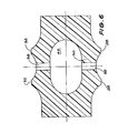
- the ring body is substantially diamond-shaped in section with an inner circumferential seal wall, the first pair of sealing lips projecting from the seal wall, the portion of the seal wall lying between the pair of lips constituting the mid-portion of the ring body, a pair of mutually inclined seal walls each of which extends from a respective end of the inner circumferential seal wall and is inclined to the latter, a second pair of mutually separated sealing lips defined by the ends of the inclined seal walls, the inner seal wall and the pair of mutually inclined seal walls defining between them an annular cavity, an aperture defined by the mid portion and passing through the same which permits, after installation, the imposition of a common sealing pressure on all four lips.
- the ring seal comprises a ring body of modified C- section, with an inner circumferential seal wall, a first pair of sealing lips projecting from the seal wall for containing the spigot pipe, the portion of the seal wall lying between the pair of lips constituting the mid-portion of the ring body, and a pair of annular end walls for contacting the side walls of the seal groove, a pair of outer circumferential seal walls each of which partly overlies the inner circumferential seal wall and terminates in a sealing lip for containing the cup, and at least one perforation defined by the mid-portion and passing through the same which permits, after installation, the imposition of a common sealing pressure on all four lips.
- the ring seal is characterised by a ring body, an annular cavity defined by the ring body, a pair of annular sealing lips axially spaced on the ring body and joined by a mid-portion of the body, and a passage through the ring body which defined a fluid path from the zone between the sealing lips to a test orifice in one of the pipes.
- a liyuid containing a root growth-inhibiting compound may injected into a hollow annular space defined by or formed in the ring body. When completed a perforation in the pipe cup through which the liquid was injected may be closed. Alternatively the liyuid may be injected into the hollow annular space by displacing a portion of the lip seal from the pipe against which it seals, with a cannula through which the liquid is introduced.
- the pipes may be made of steel, cast iron, nonferrous metal, concrete, asbestos cement, fibre reinforced plastics, extruded thermoplastics, vitrified clay, glass, ceramic and the like.
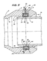
- a fibreglass and resin pipe 2 has a cup 4 with a square groove 6 moulded or formed therein during manufacture.
- the entrance to the cup has a chamfer 8 and the shoulder 10 where the cup meets the pipe is inclined.
- the interior faces 12, 14 of the cup are tapered to the groove as shown.
- the spigot 16 of the joining pipe has a chamfer 18 which seats on the shoulder 10 if the two pipes are pushed hard together.
- the seal ring 20 is of generally hollow rectangular cross section having an inner circumferential seal wall 22 and an outer circumferential seal wall 24 joined by end walls 26. These four walls enclose a hollow 44.
- the seal wall 22 has a pair of lip seals 28 projecting from its surface which can undergo only limited axial separation during jointing because they are connected by the mid-portion 30 of seal wall 22.
- wall 24 has a pair of lip seals 32. The latter engage the groove bed 33 while the inner lips 28 engage the spigot 16.
- the lips 28 and 32 define between them and the surfaces which they engage an inner annular pocket 34 and an outer annular pocket 36. These two pockets are connected by one or more perforations 38 which pass through both seal walls 22, 24 and the hollow 44.
- the cup has a bore 40 stopped by cap 42 which bore terminates in pocket 36.
- the purpose of the bore 40 is to permit the joint to be tested.
- a hand pump and gauge (not shown) is connected to bore 40 so that the two pockets 34, 36 and the hollow 44 in the ring body are pressurized to the appropriate test pressure for the particular fluid the pipes are to carry.
- the next joint is made so that sufficient time elapses for any leakage present to show on the gauge. If no pressure fall is evident the pressure source is disconnected and the cap 42 is replaced.
- FIG. 4 From a study of FIG. 4 it will be seen that it is not necessary to have a seal section in which both pairs of seals are mutually connected.
- the groove 6 has a central rib 46 which provides a separate groove 48, 50 for each outer lip seal 32. When pressurised the seals 32 will deform somewhat as shown in FIG. 2.
- the ring seal is a modified sleeve with a central cavity 58 and central pipe stop 60.
- the sleeve has ends 62 which locate it on a rigid coupler 64 provided with the threaded test bores 40.
- the inner lip seals 28 and outer lip seals 32 occupy the same relative positions as in the other seals described above.
- seals described in the above embodiments are made of neoprene but other rubber like polymers as are already used for seals may be used.
Landscapes
- Engineering & Computer Science (AREA)
- General Engineering & Computer Science (AREA)
- Physics & Mathematics (AREA)
- Fluid Mechanics (AREA)
- Mechanical Engineering (AREA)
- Joints With Sleeves (AREA)
- Flanged Joints, Insulating Joints, And Other Joints (AREA)
Applications Claiming Priority (2)
| Application Number | Priority Date | Filing Date | Title |
|---|---|---|---|
| AUPF336482 | 1982-03-29 | ||
| AU3364/82 | 1982-03-29 |
Publications (2)
| Publication Number | Publication Date |
|---|---|
| EP0091254A2 true EP0091254A2 (fr) | 1983-10-12 |
| EP0091254A3 EP0091254A3 (fr) | 1984-01-04 |
Family
ID=3769439
Family Applications (1)
| Application Number | Title | Priority Date | Filing Date |
|---|---|---|---|
| EP83301725A Ceased EP0091254A3 (fr) | 1982-03-29 | 1983-03-28 | Raccord de tuyaux et garniture |
Country Status (4)
| Country | Link |
|---|---|
| US (1) | US4529211A (fr) |
| EP (1) | EP0091254A3 (fr) |
| AU (1) | AU1298283A (fr) |
| DK (1) | DK138883A (fr) |
Cited By (7)
| Publication number | Priority date | Publication date | Assignee | Title |
|---|---|---|---|---|
| EP0340385A3 (en) * | 1988-05-06 | 1990-08-29 | Firma Carl Freudenberg | Inflatable sealing |
| EP0390746A3 (fr) * | 1989-03-31 | 1991-03-06 | Geberit AG | Connexion étanche et démontable entre un ou plusieurs tuyaux en matière plastique et un élément de jonction |
| EP0390747A3 (fr) * | 1989-03-31 | 1991-04-03 | Geberit AG | Raccord étanche, notamment pour tuyaux à plusieurs couches en matière plastique |
| DE4325349A1 (de) * | 1993-07-28 | 1995-02-02 | Kirchner Fraenk Rohr | Verbindungsvorrichtung |
| WO2001084035A1 (fr) * | 2000-05-02 | 2001-11-08 | Volvo Lastvagnar Ab | Appareil et procede pour sceller et verrouiller un point divisible entre une premiere et une seconde parties de canal |
| DE102010039964A1 (de) * | 2010-08-31 | 2012-03-01 | Siemens Aktiengesellschaft | Berstschutzvorrichtung für einen Anschlusskasten einer elektrischen Maschine |
| DE102013213737A1 (de) * | 2013-07-12 | 2015-01-15 | Siegthalerfabrik Gmbh | Flansch zur Verbindung zweier Bauteile, insbesondere eines Turms einer Windkraftanlage |
Families Citing this family (10)
| Publication number | Priority date | Publication date | Assignee | Title |
|---|---|---|---|---|
| JPH0429184Y2 (fr) * | 1984-09-26 | 1992-07-15 | ||
| US5076594A (en) * | 1988-11-10 | 1991-12-31 | Baugh Hollis A | Sealing connection between tubular members |
| DE4027920A1 (de) * | 1990-09-03 | 1992-03-05 | Karl Eickmann | Vervollkommnungen fuer hochdruck aggregate |
| US5687976A (en) * | 1996-05-10 | 1997-11-18 | Vertex, Inc. | Symmetrical gasket for a pipe joint |
| US6719302B2 (en) | 2001-07-02 | 2004-04-13 | Vertex, Inc. | Symmetrical gasket for a pipe joint with increased surface contact |
| GB2468075B (en) * | 2007-11-05 | 2011-03-23 | Cameron Int Corp | Self-energizing annular seal |
| US8297191B2 (en) * | 2009-07-31 | 2012-10-30 | The United States Of America As Represented By The Secretary Of The Navy | Pressure seal |
| JP6254981B2 (ja) * | 2015-08-12 | 2017-12-27 | ファナック株式会社 | レーザ発振器の真空容器 |
| US10744527B2 (en) * | 2016-08-23 | 2020-08-18 | Viking Group, Inc. | Low torque sprinkler fitting and method of manufacture |
| US11872425B2 (en) | 2021-02-17 | 2024-01-16 | Minimax Viking Research & Development Gmbh | Fire protection systems and methods using fire protection devices installed in pipe fittings with an internally housed seal member |
Family Cites Families (12)
| Publication number | Priority date | Publication date | Assignee | Title |
|---|---|---|---|---|
| DE7125200U (de) * | 1971-11-18 | Eckstein K | Elastischer Dichtungsring für Muffenrohr-Verbindungen | |
| US1818985A (en) * | 1928-03-17 | 1931-08-18 | Smith Corp A O | Pipe coupling |
| US1945293A (en) * | 1931-10-13 | 1934-01-30 | Ralph H Pierce | Pipe joint |
| FR849454A (fr) * | 1938-07-29 | 1939-11-24 | Joint étanche et son mode d'application | |
| GB734385A (en) * | 1952-12-12 | 1955-07-27 | Eternit | Improvements in joints for asbestos-cement tubes suitable for conveying fluid |
| DE911444C (de) * | 1953-02-10 | 1954-05-13 | Kupfer Asbest Co | Dichtung, insbesondere zur Abdichtung von Zylinderlaufbuechsen |
| US3258271A (en) * | 1963-07-29 | 1966-06-28 | Woodward Iron Company | Fluid-tight joint |
| US3363912A (en) * | 1965-05-07 | 1968-01-16 | John W. Holloway | Seal gasket |
| DE1475890B2 (de) * | 1965-08-28 | 1969-10-30 | The Mead Corp., Dayton, Ohio (V.St.A.) | Muffenrohrdichtung |
| FR1491334A (fr) * | 1966-05-27 | 1967-08-11 | Dispositif de liaison étanche entre deux éléments tubulaires et assemblage en comportant application | |
| US3695637A (en) * | 1970-05-06 | 1972-10-03 | Satterthwaite James G | Inflatable coupling |
| US4063743A (en) * | 1976-06-14 | 1977-12-20 | Mesta Machine Company | Sealing arrangement for a rotatable member |
-
1983
- 1983-03-25 US US06/479,648 patent/US4529211A/en not_active Expired - Fee Related
- 1983-03-25 DK DK138883A patent/DK138883A/da not_active Application Discontinuation
- 1983-03-28 EP EP83301725A patent/EP0091254A3/fr not_active Ceased
- 1983-03-29 AU AU12982/83A patent/AU1298283A/en not_active Abandoned
Cited By (10)
| Publication number | Priority date | Publication date | Assignee | Title |
|---|---|---|---|---|
| EP0340385A3 (en) * | 1988-05-06 | 1990-08-29 | Firma Carl Freudenberg | Inflatable sealing |
| EP0390746A3 (fr) * | 1989-03-31 | 1991-03-06 | Geberit AG | Connexion étanche et démontable entre un ou plusieurs tuyaux en matière plastique et un élément de jonction |
| EP0390747A3 (fr) * | 1989-03-31 | 1991-04-03 | Geberit AG | Raccord étanche, notamment pour tuyaux à plusieurs couches en matière plastique |
| DE4325349A1 (de) * | 1993-07-28 | 1995-02-02 | Kirchner Fraenk Rohr | Verbindungsvorrichtung |
| DE4325349C2 (de) * | 1993-07-28 | 1998-01-15 | Kirchner Fraenk Rohr | Verbindungsvorrichtung |
| WO2001084035A1 (fr) * | 2000-05-02 | 2001-11-08 | Volvo Lastvagnar Ab | Appareil et procede pour sceller et verrouiller un point divisible entre une premiere et une seconde parties de canal |
| DE102010039964A1 (de) * | 2010-08-31 | 2012-03-01 | Siemens Aktiengesellschaft | Berstschutzvorrichtung für einen Anschlusskasten einer elektrischen Maschine |
| DE102010039964B4 (de) * | 2010-08-31 | 2012-07-05 | Siemens Aktiengesellschaft | Berstschutzvorrichtung für einen Anschlusskasten einer elektrischen Maschine |
| DE102013213737A1 (de) * | 2013-07-12 | 2015-01-15 | Siegthalerfabrik Gmbh | Flansch zur Verbindung zweier Bauteile, insbesondere eines Turms einer Windkraftanlage |
| EP2826932A3 (fr) * | 2013-07-12 | 2015-04-08 | Siegthalerfabrik GmbH | Bride de liaison entre deux composants, en particulier une tour d'une éolienne |
Also Published As
| Publication number | Publication date |
|---|---|
| DK138883D0 (da) | 1983-03-25 |
| EP0091254A3 (fr) | 1984-01-04 |
| AU1298283A (en) | 1983-10-06 |
| US4529211A (en) | 1985-07-16 |
| DK138883A (da) | 1983-09-30 |
Similar Documents
| Publication | Publication Date | Title |
|---|---|---|
| US4529211A (en) | Pipe joint and seal | |
| US3637239A (en) | Thrust-resistant pipe joint | |
| US6575430B1 (en) | Hydraulic coupling with dovetail seal having multiple radial sealing surfaces | |
| US7111874B2 (en) | Floating seal for undersea hydraulic coupling | |
| EP0100326B1 (fr) | Raccord pour fluides et son procede de fabrication | |
| US3081102A (en) | Gasket for telescoping joint | |
| US3860270A (en) | Apparatus for effecting a connection to a tubular member or the like | |
| EP0543103B1 (fr) | Dispositif d'étanchéité | |
| US11255474B2 (en) | Tubular joint | |
| EP1332312B1 (fr) | Raccord d'extremite pour haute temperature | |
| US6179002B1 (en) | Hydraulic coupling with pressure-energized dovetail seal | |
| US20040036280A1 (en) | High temperature end fitting and method of use | |
| US20010045709A1 (en) | Seal ring and joint | |
| JPS6283591A (ja) | 加圧流体装置用シ−ル | |
| US3563574A (en) | Coupling for plastic pipe | |
| US12117080B2 (en) | Gasket assembly and seal carrier | |
| US2653040A (en) | Pipe coupling | |
| US9222609B1 (en) | Seal for use in subsea connections and subsea connections employing such a seal | |
| US2778662A (en) | Axially and radially sealed divided sleeve type pipe clamp | |
| IE891375L (en) | Pipe connection | |
| CA2438147A1 (fr) | Joint etanche pour joints filetes de pipelines, et son utilisation | |
| US3360284A (en) | Split t | |
| RU2191948C2 (ru) | Шарнирное соединение труб | |
| JPS59200889A (ja) | 管継手及びそのシ−ル | |
| EP0506356A2 (fr) | Arrangement de garniture pour raccords de tuyaux et raccord de tuyaux muni de celui-ci |
Legal Events
| Date | Code | Title | Description |
|---|---|---|---|
| PUAI | Public reference made under article 153(3) epc to a published international application that has entered the european phase |
Free format text: ORIGINAL CODE: 0009012 |
|
| AK | Designated contracting states |
Designated state(s): AT BE CH DE FR GB IT LI LU NL SE |
|
| PUAL | Search report despatched |
Free format text: ORIGINAL CODE: 0009013 |
|
| AK | Designated contracting states |
Designated state(s): AT BE CH DE FR GB IT LI LU NL SE |
|
| 17P | Request for examination filed |
Effective date: 19840702 |
|
| STAA | Information on the status of an ep patent application or granted ep patent |
Free format text: STATUS: THE APPLICATION HAS BEEN REFUSED |
|
| 18R | Application refused |
Effective date: 19871212 |