EP0091466B1 - Method and apparatus for registering the use of a television receiver in connection with at least one video tape player - Google Patents
Method and apparatus for registering the use of a television receiver in connection with at least one video tape player Download PDFInfo
- Publication number
- EP0091466B1 EP0091466B1 EP82903194A EP82903194A EP0091466B1 EP 0091466 B1 EP0091466 B1 EP 0091466B1 EP 82903194 A EP82903194 A EP 82903194A EP 82903194 A EP82903194 A EP 82903194A EP 0091466 B1 EP0091466 B1 EP 0091466B1
- Authority
- EP
- European Patent Office
- Prior art keywords
- signal
- signals
- envelopes
- smoothed
- reference signal
- Prior art date
- Legal status (The legal status is an assumption and is not a legal conclusion. Google has not performed a legal analysis and makes no representation as to the accuracy of the status listed.)
- Expired
Links
- 238000000034 method Methods 0.000 title claims abstract description 14
- 230000005236 sound signal Effects 0.000 claims description 13
- 238000001914 filtration Methods 0.000 claims description 3
- 238000012544 monitoring process Methods 0.000 abstract description 11
- 238000001228 spectrum Methods 0.000 abstract 1
- 230000001960 triggered effect Effects 0.000 description 5
- 230000001105 regulatory effect Effects 0.000 description 3
- 230000000903 blocking effect Effects 0.000 description 1
- 238000010586 diagram Methods 0.000 description 1
- 230000008030 elimination Effects 0.000 description 1
- 238000003379 elimination reaction Methods 0.000 description 1
- 238000005259 measurement Methods 0.000 description 1
- 230000000737 periodic effect Effects 0.000 description 1
Images

Classifications
-
- G—PHYSICS
- G10—MUSICAL INSTRUMENTS; ACOUSTICS
- G10L—SPEECH ANALYSIS TECHNIQUES OR SPEECH SYNTHESIS; SPEECH RECOGNITION; SPEECH OR VOICE PROCESSING TECHNIQUES; SPEECH OR AUDIO CODING OR DECODING
- G10L15/00—Speech recognition
Definitions
- the present invention relates to a method and an apparatus of registering the use of a television receiver in connection with at least one video tape player, in which method and apparatus an audio signal from the television receiver forms an analysis signal and an audio signal from the video tape player a reference signal, the concordance of said signals being determined by forming smoothed signals or envelopes of the analysis signal and the reference signal and generating a pulse train for each of the smoothed signals or envelopes, which pulse trains represent the analysis signal and the reference signal respectively and are compared with each other at regular intervals.
- a device is previously known for monitoring pulse sources.
- This device is a circuit of so called “watch-dog” type and it is disposed to start an alarm, if one of the pulse sources should fail.
- a telephone equipment is described.
- the call signal and the free tone are first integrated and then one of the signals is inverted, before the signals are differentiated and once again rectified so that two pulse trains of desired shape, g and h in Figure 2, are obtained for supply to each input of a bistable flip-flop MV.
- the flip-flop MV will then oscillate between its two stable positions as long as these control pulses are supplied. However, if one or both of the pulse trains disappear, the flip-flop will stop in one of its positions, the subsequent alarm AL being triggered.
- DE-A-2 406 485 discloses a circuit for comparison of frequencies of two pulse trains, a caution signal being delivered if the difference in frequency exceeds a predetermined value. Therefore one of the pulse trains is fed into the input 10 and for each pulse a shift, to the left in the Figure, of information contained in the shift register 20 takes place. To the other input 11 the other pulse train is supplied and for each pulse in this train the information in the shift register 20 is shifted to the right in the figure.
- the unit 29 is triggered to deliver a caution signal. If instead the frequency of pulse train 11 exceeds the frequency of the pulse train on input 10 so much that the information during a predetermined time is shifted to the right end stage in the shift register 20, the unit 30 will be triggered to deliver the caution signal.
- FR-A-1 509 196 describes a method for filtering out the essential information of a vowel signal, disturbed by noise.
- the method is intended for voice coding systems.
- the method is based on the principal that the average value of adjacent signal portions are weighted, said weight being a function of the position in the interval, followed by the summation of the weighted periods divided by a given number. After the measurement the measuring interval is displaced with a length which is equal to the length of the average period thus measured.
- the circuit shown in the figure comprises a non-linear element NLG and a band filter BP for eliminating the basic component in the vowel signal.
- the commutation circuit ND the zero passages of the vowel signal are detected and the output signal is supplied to a pulse forming circuit IF.
- the units I-IV the different algebraical operations are performed as indicated above.
- DE-A-2 620 059 discloses a "watch-dog" circuit too for monitoring digital signals and synchronization signals in a crossing point.
- the circuit comprises a first register Sp1. To one of its inputs D1 the digital signal is fed and to the other input T1 the synchronization signal is fed.
- the digital signal to be monitored is read with a synchronization frequency into the register Sp1 by a gate Tor.
- the gate Tor is blocking as soon as a logic 1 is read into the register Sp1. Thus the register content is no more changed before the end of the monitoring period T0. In the beginning of the next monitoring period the register Sp1 is reset and the gate Tor is opened.
- the register Sp1 thus delivers an output signal if at least one logic 1 has appeared during the monitoring period.
- the purpose of the circuit according to this document is to monitor the presence of a signal on the input D1 by a periodic scanning of the input.
- the present invention relates to a method and an apparatus for registering the use of a television receiver in connection with at least one video tape player by determining the agreement between an analysis signal delivered by the television receiver and at least one reference signal delivered by a video tape player.
- the object of the present invention is to propose a method and provide an apparatus for registering the use of a television receiver in connection with at least one video tape player by monitoring a characteristic audio signal from the television receiver and comparing it with at least one reference signal, delivered by a video tape player.
- the invention is suitable for use in monitoring a situation with several video tape players connectable to a television receiver. With the invention it is then possible to determine whether the analysis from the television receiver agrees with one or more given reference signals from the video tape players and in the latter case which one of the reference signals it agrees with.
- the signals are smoothed and pulse trains corresponding to said smoothed signals or envelopes are generated, a predetermined number of consecutive agreements in the pulse train being required for the analysis signal from the television receiver being considered to agree with a reference signal from a video tape player.
- This is a safety measure so that the signals will not be registered as being in agreement with randomly coinciding pulses in the corresponding pulse trains.
- the method in accordance with the invention can be utilized for comparing a signal from a television receiver with signals from an optional number of video tape players, the apparatus in accordance with the invention being built up with a corresponding number of parallel branches for analysis of the signals and comparison of the analysis signal from a television receiver with each of the given signals from video tape players.
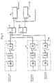
- Figure 1 is a block diagram illustrating the principles on which the invention is based
- Figure 2 is an example of the use of the apparatus in accordance with the invention for automatic debiting of utilized video service.
- the rectifier 2 comprises two operation amplifiers, diodes and resistances, and the filter 4 is an active filter with operation amplifier.
- the signal envelope or smoothed signal obtained from the filter output is applied to one input of a comparator 6.
- a threshold signal U Ref1 is applied to the other input of the comparator 6 to prevent undesired changes of the state of the comparator due to noise.
- An output pulse is obtained from the comparator when the input signal exceeds the applied threshold signal and the pulse length is determined by the duration of this state.
- the comparator 6 is an operation amplifier.
- the threshold signal U Ref2 to the comparators in the reference signal circuits 8, 10 is somewhat higher than the threshold signal U Re" .
- the output pulses from the comparators in the reference signal circuits 8 and 10 will thus be somewhat narrower than the output pulses from the comparator 6, and the reference signal pulses will be contained within the pulses from the comparator 6.
- the output pulse train from the comparator 6 is applied to the data input of two D flip-flops 12, 14.
- the output pulse train from the reference signal circuits 8 and 10 are applied as clock signals to the flip-flops 12 and 14, respectively.
- the flip-flops 12, '14 go to a one state (send an output pulse) for concordant signals.
- the flip-flops thus have an AND gate function.
- the flip-flops gate on the flanks from the pulses from the comparators, and by URef2 being greater than U Ref1 the output pulses from the reference signal circuits are, in time, contained within the pulses from the comparator 6, i.e. the signal from the comparator 6 is at the flip-flops 12, 14, when there is applied to these the output pulses from the reference signal circuits 8, 10, the latter pulses also having the character of gate pulses.
- the registers 16, 18 are scanned at regular intervals by applying a scanning pulse, and at a predetermined number of consecutive, positive answers regarding the concordance of the compared pulse trains said registers 16, 18 trigger a following counter (not shown in Figure 1
- FIG. 1 The apparatus of Figure 1 is shown in Figure 2 in use for automatic debiting of utilized video service in a hotel or the like, where the ordinary television programs or one or more available video programs can be connected to the television receivers in the rooms.
- the video program utilization shall be debited, but not that of the ordinary TV programs.
- This is enabled with the present invention in a simple manner without any extra equipment on the television receiver.
- the principle forming the basis of the invention here is that speech and music consist of more or less distinct sound packages, e.g. accentuated syllables, individual words, accentuated portions of a beat in music etc., the smoothed signals or envelopes of these sound packages being compared with the smoothed signal or envelope of the reference sound package.
- a television receiver 20 is connected to an antenna 22 for receiving ordinary television programs, and to two video tape players 24, 26 for receiving programs from them.
- An audio signal is taken from the television receiver 20 and fed to a regulating amplifier 28.
- the audio signal is suitably taken out before the television receiver volume control via a buffer amplifier to separate the receiver high voltage from the signal taken out.
- the signal level is adjusted by means of the regulating amplifier 28 so that a suitable level is applied to the input of the comparator 6.
- a feedback loop is arranged for this purpose from the comparator input to the amplifier 28. After the amplifier 28 there is the circuit described in connection with Figure 1, comprising the rectifier 2, bandpass filter 4 and comparator 6.
- the audio signals from the video tape players 24, 26 are treated in the same way as the audio signal from the television receiver 20 in like circuits 30, 32, 34, 36.
- the threshold signal U Ref2 applied to the comparator 36 is higher than the threshold signal URen which is applied to the comparator 6.
- the output signal from the comparator 6 is applied to the flip-flops 12 and 14, and the output signals from the comparator 36 are applied as clock signals to each of the flip-flops 12 and 14.
- the video tape players 24, 26 can naturally be connected to several different television sets, and for that reason there is schematically indicated outputs at 38 and 40 for taking the output signals from the comparators 36 to other flip-flops, which are also supplied with the processed audio signal from other television receivers.
- the registers are scanned at regular intervals.
- the scanning interval for the shift registers can be of the order of magnitude of one minute, and the number of consecutive positive answers for triggering the following counter can be 6 or 7.
- the shift registers will thus act as a unit for generating a time lag of 6 or 7 minutes before the counter is triggered.
- the shift registers 16, 18 are further arranged so that the whole register is zeroed after two consecutive, negative answers regarding the concordance of the compared pulse trains.
- the counter can be one of the type used in ordinary telephone conversation counting, and it is triggered at regular intervals, e.g. in the range of 0.1-100 seconds.
Landscapes
- Engineering & Computer Science (AREA)
- Computational Linguistics (AREA)
- Health & Medical Sciences (AREA)
- Audiology, Speech & Language Pathology (AREA)
- Human Computer Interaction (AREA)
- Physics & Mathematics (AREA)
- Acoustics & Sound (AREA)
- Multimedia (AREA)
- Measurement Of Mechanical Vibrations Or Ultrasonic Waves (AREA)
- Signal Processing Not Specific To The Method Of Recording And Reproducing (AREA)
- Signal Processing For Digital Recording And Reproducing (AREA)
- Testing, Inspecting, Measuring Of Stereoscopic Televisions And Televisions (AREA)
- Apparatus For Radiation Diagnosis (AREA)
- Inspection Of Paper Currency And Valuable Securities (AREA)
- Investigating Or Analyzing Materials By The Use Of Magnetic Means (AREA)
- Investigating Or Analysing Biological Materials (AREA)
- Television Signal Processing For Recording (AREA)
- Manipulation Of Pulses (AREA)
Priority Applications (1)
| Application Number | Priority Date | Filing Date | Title |
|---|---|---|---|
| AT82903194T ATE23244T1 (de) | 1981-10-20 | 1982-10-20 | Verfahren und vorrichtung zur erfassung der verwendung eines fernsehgeraetes in zusammenhang mit mindestens einem videobandabspielgeraet. |
Applications Claiming Priority (2)
| Application Number | Priority Date | Filing Date | Title |
|---|---|---|---|
| SE8106186 | 1981-10-20 | ||
| SE8106186A SE8106186L (sv) | 1981-10-20 | 1981-10-20 | Forfarande och anordning for att bestemma en analyssignals overenstemmelse med minst en referenssignal |
Publications (2)
| Publication Number | Publication Date |
|---|---|
| EP0091466A1 EP0091466A1 (en) | 1983-10-19 |
| EP0091466B1 true EP0091466B1 (en) | 1986-10-29 |
Family
ID=20344829
Family Applications (1)
| Application Number | Title | Priority Date | Filing Date |
|---|---|---|---|
| EP82903194A Expired EP0091466B1 (en) | 1981-10-20 | 1982-10-20 | Method and apparatus for registering the use of a television receiver in connection with at least one video tape player |
Country Status (11)
| Country | Link |
|---|---|
| US (1) | US4511917A (da) |
| EP (1) | EP0091466B1 (da) |
| JP (1) | JPS58501786A (da) |
| AT (1) | ATE23244T1 (da) |
| DE (1) | DE3274044D1 (da) |
| DK (1) | DK277583A (da) |
| FI (1) | FI72398C (da) |
| IT (1) | IT1152743B (da) |
| NO (1) | NO832204L (da) |
| SE (1) | SE8106186L (da) |
| WO (1) | WO1983001526A1 (da) |
Cited By (1)
| Publication number | Priority date | Publication date | Assignee | Title |
|---|---|---|---|---|
| DE3720882A1 (de) * | 1987-06-24 | 1989-01-05 | Media Control Musik Medien | Verfahren und schaltungsanordnung zum automatischen wiedererkennen von signalfolgen |
Families Citing this family (33)
| Publication number | Priority date | Publication date | Assignee | Title |
|---|---|---|---|---|
| GB2138642B (en) * | 1983-04-22 | 1986-08-20 | Video Res | Audience rating measuring system for television receivers and video tape recorders |
| US4697209A (en) * | 1984-04-26 | 1987-09-29 | A. C. Nielsen Company | Methods and apparatus for automatically identifying programs viewed or recorded |
| JPS6121695A (ja) * | 1984-07-10 | 1986-01-30 | Video Res:Kk | 視聴率測定システムにおけるビデオテ−プレコ−ダの動作状態検出方式 |
| US4677466A (en) * | 1985-07-29 | 1987-06-30 | A. C. Nielsen Company | Broadcast program identification method and apparatus |
| US4739398A (en) * | 1986-05-02 | 1988-04-19 | Control Data Corporation | Method, apparatus and system for recognizing broadcast segments |
| US4847685A (en) * | 1987-08-07 | 1989-07-11 | Audience Information Measurement System | Audience survey system |
| GB9221678D0 (en) * | 1992-10-15 | 1992-11-25 | Taylor Nelson Group Limited | Identifying a received programme stream |
| DK46493D0 (da) * | 1993-04-22 | 1993-04-22 | Frank Uldall Leonhard | Metode for signalbehandling til bestemmelse af transientforhold i auditive signaler |
| US5485518A (en) * | 1993-09-30 | 1996-01-16 | Yellowstone Environmental Science, Inc. | Electronic media program recognition and choice |
| US5594934A (en) * | 1994-09-21 | 1997-01-14 | A.C. Nielsen Company | Real time correlation meter |
| US8094949B1 (en) | 1994-10-21 | 2012-01-10 | Digimarc Corporation | Music methods and systems |
| US6560349B1 (en) * | 1994-10-21 | 2003-05-06 | Digimarc Corporation | Audio monitoring using steganographic information |
| US5757939A (en) * | 1994-12-22 | 1998-05-26 | Lucent Technologies Inc. | Method for demonstrating sound quality differences between audio samples |
| US6760463B2 (en) * | 1995-05-08 | 2004-07-06 | Digimarc Corporation | Watermarking methods and media |
| US6505160B1 (en) | 1995-07-27 | 2003-01-07 | Digimarc Corporation | Connected audio and other media objects |
| US6829368B2 (en) * | 2000-01-26 | 2004-12-07 | Digimarc Corporation | Establishing and interacting with on-line media collections using identifiers in media signals |
| US7562392B1 (en) | 1999-05-19 | 2009-07-14 | Digimarc Corporation | Methods of interacting with audio and ambient music |
| US6289514B1 (en) | 1999-03-29 | 2001-09-11 | Qcom Tv, Inc. | System and method for the near-real time capture and reporting of large population consumer behaviors concerning television use |
| US7302574B2 (en) * | 1999-05-19 | 2007-11-27 | Digimarc Corporation | Content identifiers triggering corresponding responses through collaborative processing |
| US8095796B2 (en) * | 1999-05-19 | 2012-01-10 | Digimarc Corporation | Content identifiers |
| US8205237B2 (en) | 2000-09-14 | 2012-06-19 | Cox Ingemar J | Identifying works, using a sub-linear time search, such as an approximate nearest neighbor search, for initiating a work-based action, such as an action on the internet |
| US8010988B2 (en) * | 2000-09-14 | 2011-08-30 | Cox Ingemar J | Using features extracted from an audio and/or video work to obtain information about the work |
| US7129972B2 (en) * | 2000-09-25 | 2006-10-31 | Canon Kabushiki Kaisha | Image sensing device for transmitting images |
| WO2002051063A1 (en) | 2000-12-21 | 2002-06-27 | Digimarc Corporation | Methods, apparatus and programs for generating and utilizing content signatures |
| US7046819B2 (en) * | 2001-04-25 | 2006-05-16 | Digimarc Corporation | Encoded reference signal for digital watermarks |
| US7328153B2 (en) * | 2001-07-20 | 2008-02-05 | Gracenote, Inc. | Automatic identification of sound recordings |
| US20040091111A1 (en) * | 2002-07-16 | 2004-05-13 | Levy Kenneth L. | Digital watermarking and fingerprinting applications |
| US9015740B2 (en) | 2005-12-12 | 2015-04-21 | The Nielsen Company (Us), Llc | Systems and methods to wirelessly meter audio/visual devices |
| US20080051029A1 (en) * | 2006-08-25 | 2008-02-28 | Bradley James Witteman | Phone-based broadcast audio identification |
| US9124769B2 (en) | 2008-10-31 | 2015-09-01 | The Nielsen Company (Us), Llc | Methods and apparatus to verify presentation of media content |
| US8645984B1 (en) * | 2013-02-05 | 2014-02-04 | Samsung Electronics Co., Ltd. | Method and system for verifying content authenticity in smart TV |
| US10121517B1 (en) | 2018-03-16 | 2018-11-06 | Videolicious, Inc. | Systems and methods for generating audio or video presentation heat maps |
| US11698405B2 (en) | 2021-07-09 | 2023-07-11 | Rohde & Schwarz Gmbh & Co. Kg | Method and system for determining at least one contribution of at least one device under test of a radio frequency device chain |
Family Cites Families (15)
| Publication number | Priority date | Publication date | Assignee | Title |
|---|---|---|---|---|
| DE1197922B (de) * | 1960-10-27 | 1965-08-05 | Int Standard Electric Corp | UEberwachungseinrichtung fuer mehrere Impulsquellen |
| GB1012765A (en) * | 1964-03-06 | 1965-12-08 | Standard Telephones Cables Ltd | Apparatus for the analysis of waveforms |
| DE1200884B (de) * | 1964-04-06 | 1965-09-16 | Ibm Deutschland | Verfahren zum Glaetten der Grundtoninformation in impulserregten Kanalvocodersystemen |
| US3456201A (en) * | 1965-12-03 | 1969-07-15 | Nasa | System for monitoring signal amplitude ranges |
| US3531583A (en) * | 1966-07-28 | 1970-09-29 | Zenith Radio Corp | Subscription television receiver |
| US3597636A (en) * | 1968-06-21 | 1971-08-03 | Svyatoslav Anatolievich Kravch | Indicator of zero phase angle between two voltages |
| US3639843A (en) * | 1970-07-20 | 1972-02-01 | Hewlett Packard Co | Voltage to pulse ratio converter |
| DE2039557C3 (de) * | 1970-08-08 | 1979-03-29 | Philips Patentverwaltung Gmbh, 2000 Hamburg | Anordnung zum Frequenzvergleich zweier Impulsfolgefrequenzen |
| US3919479A (en) * | 1972-09-21 | 1975-11-11 | First National Bank Of Boston | Broadcast signal identification system |
| GB1454531A (en) * | 1973-02-12 | 1976-11-03 | Ferranti Ltd | Frequency comparison circuit arrangements |
| US4031543A (en) * | 1974-03-11 | 1977-06-21 | Berkeley Varitronics Systems | Communication system |
| US4234883A (en) * | 1974-09-26 | 1980-11-18 | Gte Sylvania Incorporated | Noise adaptive correlator |
| US4028493A (en) * | 1975-12-22 | 1977-06-07 | International Business Machines Corporation | Call progress signal detector |
| DE2620059C3 (de) * | 1976-05-06 | 1978-10-26 | Siemens Ag, 1000 Berlin Und 8000 Muenchen | Anordnung zur gleichzeitigen Überwachung von Digital- und Taktsignalen |
| US4142156A (en) * | 1976-12-23 | 1979-02-27 | Veripen, Inc. | Control signal apparatus for CATV system |
-
1981
- 1981-10-20 SE SE8106186A patent/SE8106186L/xx not_active Application Discontinuation
-
1982
- 1982-10-20 AT AT82903194T patent/ATE23244T1/de not_active IP Right Cessation
- 1982-10-20 WO PCT/SE1982/000339 patent/WO1983001526A1/en not_active Ceased
- 1982-10-20 DE DE8282903194T patent/DE3274044D1/de not_active Expired
- 1982-10-20 JP JP57503164A patent/JPS58501786A/ja active Pending
- 1982-10-20 IT IT23827/82A patent/IT1152743B/it active
- 1982-10-20 EP EP82903194A patent/EP0091466B1/en not_active Expired
- 1982-10-20 US US06/514,808 patent/US4511917A/en not_active Expired - Fee Related
-
1983
- 1983-06-15 FI FI832177A patent/FI72398C/fi not_active IP Right Cessation
- 1983-06-16 DK DK277583A patent/DK277583A/da not_active Application Discontinuation
- 1983-06-17 NO NO832204A patent/NO832204L/no unknown
Cited By (1)
| Publication number | Priority date | Publication date | Assignee | Title |
|---|---|---|---|---|
| DE3720882A1 (de) * | 1987-06-24 | 1989-01-05 | Media Control Musik Medien | Verfahren und schaltungsanordnung zum automatischen wiedererkennen von signalfolgen |
Also Published As
| Publication number | Publication date |
|---|---|
| DK277583D0 (da) | 1983-06-16 |
| ATE23244T1 (de) | 1986-11-15 |
| DK277583A (da) | 1983-06-16 |
| FI72398B (fi) | 1987-01-30 |
| IT1152743B (it) | 1987-01-07 |
| SE8106186L (sv) | 1983-04-21 |
| US4511917A (en) | 1985-04-16 |
| EP0091466A1 (en) | 1983-10-19 |
| WO1983001526A1 (en) | 1983-04-28 |
| FI832177L (fi) | 1983-06-15 |
| JPS58501786A (ja) | 1983-10-20 |
| IT8223827A0 (it) | 1982-10-20 |
| NO832204L (no) | 1983-06-17 |
| FI832177A0 (fi) | 1983-06-15 |
| DE3274044D1 (en) | 1986-12-04 |
| FI72398C (fi) | 1987-05-11 |
Similar Documents
| Publication | Publication Date | Title |
|---|---|---|
| EP0091466B1 (en) | Method and apparatus for registering the use of a television receiver in connection with at least one video tape player | |
| US4696041A (en) | Apparatus for detecting an utterance boundary | |
| US4542525A (en) | Method and apparatus for classifying audio signals | |
| US4039754A (en) | Speech analyzer | |
| US2098956A (en) | Signaling system | |
| US4450436A (en) | Acoustic alarm repeater system | |
| Munson et al. | Loudness patterns—a new approach | |
| EP0108151B1 (en) | Secret-speech device | |
| US4718097A (en) | Method and apparatus for determining the endpoints of a speech utterance | |
| US3949177A (en) | Method for frequency-recognition in selective signal receivers for use in telecommunication, particularly telephone systems | |
| JPH04150252A (ja) | 音声/音声帯域内データ識別装置 | |
| US5970447A (en) | Detection of tonal signals | |
| EP0576980B1 (en) | A method of improving sensitivity and speech immunity of a multifrequency receiver | |
| US3546584A (en) | Apparatus for analyzing a complex waveform containing pitch synchronous information | |
| DE3102385C2 (da) | ||
| CA1200031A (en) | Adaptive signal receiving method and apparatus | |
| US4680783A (en) | Telephone security violation detection device | |
| US3600516A (en) | Voicing detection and pitch extraction system | |
| US5007069A (en) | Decoding of signals using cophase and differentiating signal detection | |
| Miller | Performance characteristics of an experimental harmonic identification pitch extraction (HIPEX) system | |
| Harris | Residual masking at low frequencies | |
| Koshikawa et al. | The information rate of the pitch signal in speech | |
| SU1244565A1 (ru) | Устройство дл определени времени окончани приработки пары трени | |
| McGonegal et al. | Speaker verification by human listeners over several speech transmission systems | |
| JPH0514232Y2 (da) |
Legal Events
| Date | Code | Title | Description |
|---|---|---|---|
| PUAI | Public reference made under article 153(3) epc to a published international application that has entered the european phase |
Free format text: ORIGINAL CODE: 0009012 |
|
| 17P | Request for examination filed |
Effective date: 19830622 |
|
| AK | Designated contracting states |
Designated state(s): AT BE CH DE FR GB LI LU NL SE |
|
| RAP1 | Party data changed (applicant data changed or rights of an application transferred) |
Owner name: KOEHLER, HANS OLOF |
|
| RAP1 | Party data changed (applicant data changed or rights of an application transferred) |
Owner name: ROBUR VISION INDUSTRIES LTD. S.A. |
|
| GRAA | (expected) grant |
Free format text: ORIGINAL CODE: 0009210 |
|
| AK | Designated contracting states |
Kind code of ref document: B1 Designated state(s): AT BE CH DE FR GB LI LU NL SE |
|
| REF | Corresponds to: |
Ref document number: 23244 Country of ref document: AT Date of ref document: 19861115 Kind code of ref document: T |
|
| REF | Corresponds to: |
Ref document number: 3274044 Country of ref document: DE Date of ref document: 19861204 |
|
| ET | Fr: translation filed | ||
| PLBE | No opposition filed within time limit |
Free format text: ORIGINAL CODE: 0009261 |
|
| STAA | Information on the status of an ep patent application or granted ep patent |
Free format text: STATUS: NO OPPOSITION FILED WITHIN TIME LIMIT |
|
| PG25 | Lapsed in a contracting state [announced via postgrant information from national office to epo] |
Ref country code: AT Effective date: 19871020 |
|
| 26N | No opposition filed | ||
| PG25 | Lapsed in a contracting state [announced via postgrant information from national office to epo] |
Ref country code: LU Free format text: LAPSE BECAUSE OF NON-PAYMENT OF DUE FEES Effective date: 19871031 Ref country code: LI Effective date: 19871031 Ref country code: CH Effective date: 19871031 Ref country code: BE Effective date: 19871031 |
|
| BERE | Be: lapsed |
Owner name: ROBUR VISION INDUSTRIES LTD S.A. Effective date: 19871031 |
|
| PG25 | Lapsed in a contracting state [announced via postgrant information from national office to epo] |
Ref country code: NL Effective date: 19880501 |
|
| NLV4 | Nl: lapsed or anulled due to non-payment of the annual fee | ||
| PG25 | Lapsed in a contracting state [announced via postgrant information from national office to epo] |
Ref country code: FR Free format text: LAPSE BECAUSE OF NON-PAYMENT OF DUE FEES Effective date: 19880630 |
|
| REG | Reference to a national code |
Ref country code: CH Ref legal event code: PL |
|
| PG25 | Lapsed in a contracting state [announced via postgrant information from national office to epo] |
Ref country code: DE Effective date: 19880701 |
|
| REG | Reference to a national code |
Ref country code: FR Ref legal event code: ST |
|
| PG25 | Lapsed in a contracting state [announced via postgrant information from national office to epo] |
Ref country code: GB Effective date: 19881020 |
|
| PG25 | Lapsed in a contracting state [announced via postgrant information from national office to epo] |
Ref country code: SE Effective date: 19881021 |
|
| GBPC | Gb: european patent ceased through non-payment of renewal fee | ||
| EUG | Se: european patent has lapsed |
Ref document number: 82903194.7 Effective date: 19890619 |