EP0091544A2 - Synchronisiervorrichtung für eine spiralförmige Fluidumverdrängermaschine - Google Patents
Synchronisiervorrichtung für eine spiralförmige Fluidumverdrängermaschine Download PDFInfo
- Publication number
- EP0091544A2 EP0091544A2 EP83101538A EP83101538A EP0091544A2 EP 0091544 A2 EP0091544 A2 EP 0091544A2 EP 83101538 A EP83101538 A EP 83101538A EP 83101538 A EP83101538 A EP 83101538A EP 0091544 A2 EP0091544 A2 EP 0091544A2
- Authority
- EP
- European Patent Office
- Prior art keywords
- scroll member
- orbiting scroll
- pockets
- housing
- keys
- Prior art date
- Legal status (The legal status is an assumption and is not a legal conclusion. Google has not performed a legal analysis and makes no representation as to the accuracy of the status listed.)
- Withdrawn
Links
Images



Classifications
-
- F—MECHANICAL ENGINEERING; LIGHTING; HEATING; WEAPONS; BLASTING
- F01—MACHINES OR ENGINES IN GENERAL; ENGINE PLANTS IN GENERAL; STEAM ENGINES
- F01C—ROTARY-PISTON OR OSCILLATING-PISTON MACHINES OR ENGINES
- F01C21/00—Component parts, details or accessories not provided for in groups F01C1/00 - F01C20/00
- F01C21/003—Systems for the equilibration of forces acting on the elements of the machine
-
- F—MECHANICAL ENGINEERING; LIGHTING; HEATING; WEAPONS; BLASTING
- F01—MACHINES OR ENGINES IN GENERAL; ENGINE PLANTS IN GENERAL; STEAM ENGINES
- F01C—ROTARY-PISTON OR OSCILLATING-PISTON MACHINES OR ENGINES
- F01C1/00—Rotary-piston machines or engines
- F01C1/02—Rotary-piston machines or engines of arcuate-engagement type, i.e. with circular translatory movement of co-operating members, each member having the same number of teeth or tooth-equivalents
- F01C1/0207—Rotary-piston machines or engines of arcuate-engagement type, i.e. with circular translatory movement of co-operating members, each member having the same number of teeth or tooth-equivalents both members having co-operating elements in spiral form
- F01C1/0215—Rotary-piston machines or engines of arcuate-engagement type, i.e. with circular translatory movement of co-operating members, each member having the same number of teeth or tooth-equivalents both members having co-operating elements in spiral form where only one member is moving
-
- F—MECHANICAL ENGINEERING; LIGHTING; HEATING; WEAPONS; BLASTING
- F01—MACHINES OR ENGINES IN GENERAL; ENGINE PLANTS IN GENERAL; STEAM ENGINES
- F01C—ROTARY-PISTON OR OSCILLATING-PISTON MACHINES OR ENGINES
- F01C17/00—Arrangements for drive of co-operating members, e.g. for rotary piston and casing
- F01C17/06—Arrangements for drive of co-operating members, e.g. for rotary piston and casing using cranks, universal joints or similar elements
- F01C17/063—Arrangements for drive of co-operating members, e.g. for rotary piston and casing using cranks, universal joints or similar elements with only rolling movement
-
- F—MECHANICAL ENGINEERING; LIGHTING; HEATING; WEAPONS; BLASTING
- F01—MACHINES OR ENGINES IN GENERAL; ENGINE PLANTS IN GENERAL; STEAM ENGINES
- F01C—ROTARY-PISTON OR OSCILLATING-PISTON MACHINES OR ENGINES
- F01C21/00—Component parts, details or accessories not provided for in groups F01C1/00 - F01C20/00
- F01C21/008—Driving elements, brakes, couplings, transmissions specially adapted for rotary or oscillating-piston machines or engines
-
- F—MECHANICAL ENGINEERING; LIGHTING; HEATING; WEAPONS; BLASTING
- F04—POSITIVE - DISPLACEMENT MACHINES FOR LIQUIDS; PUMPS FOR LIQUIDS OR ELASTIC FLUIDS
- F04C—ROTARY-PISTON, OR OSCILLATING-PISTON, POSITIVE-DISPLACEMENT MACHINES FOR LIQUIDS; ROTARY-PISTON, OR OSCILLATING-PISTON, POSITIVE-DISPLACEMENT PUMPS
- F04C29/00—Component parts, details or accessories of pumps or pumping installations, not provided for in groups F04C18/00 - F04C28/00
- F04C29/0042—Driving elements, brakes, couplings, transmissions specially adapted for pumps
- F04C29/005—Means for transmitting movement from the prime mover to driven parts of the pump, e.g. clutches, couplings, transmissions
- F04C29/0057—Means for transmitting movement from the prime mover to driven parts of the pump, e.g. clutches, couplings, transmissions for eccentric movement
-
- F—MECHANICAL ENGINEERING; LIGHTING; HEATING; WEAPONS; BLASTING
- F04—POSITIVE - DISPLACEMENT MACHINES FOR LIQUIDS; PUMPS FOR LIQUIDS OR ELASTIC FLUIDS
- F04C—ROTARY-PISTON, OR OSCILLATING-PISTON, POSITIVE-DISPLACEMENT MACHINES FOR LIQUIDS; ROTARY-PISTON, OR OSCILLATING-PISTON, POSITIVE-DISPLACEMENT PUMPS
- F04C2240/00—Components
- F04C2240/80—Other components
- F04C2240/807—Balance weight, counterweight
Definitions
- This invention relates to scroll-type fluid displacement apparatus.
- U.S. Patent No. 801,182 discloses a device including two scroll members each having an end plate and a spiroidal or involute spiral element.
- the scroll members are maintained angularly and radially offset so that both spiral elements interfit at a plurality of line contacts between their spiral curved surfaces, to thereby seal off and define at least one pair of fluid pockets.
- the relative orbital motion of these scroll members shifts the line contact along the spiral curved surfaces and, therefore, changes the volume in the fluid pockets.
- the volume of the fluid pockets increases or decreases dependent on the direction of orbital motion. Therefore, a scroll-type apparatus is applicable to compress, expand or pump fluids.
- both scroll members are supported on a crank pin or shaft which is disposed at end portions of drive shafts to accomplish the relative orbital motion between the scroll members.
- the scroll members are thereby supported in a cantilever manner. Therefore, a slant may arise between the drive shafts and the cantilever supported scroll members, whereby axial line contact between the spiral elements is not maintained.
- one of the scroll members is fixedly disposed in a housing and the axial slant of the scroll member is thereby prevented.
- the other scroll member must be supported on the crank pin of the drive shaft, therefore, axial slant of this scroll member by the cantilever support is not resolved.
- the movement of the orbiting scroll member is not rotary motion around the center of the scroll member, but is orbiting motion caused by the eccentrical movement of the crank pin moved by the rotation of the drive shaft, therefore axial slant easily arises.
- the axial slant occurs several problems arise; primarily sealing of the line contact, vibration of the apparatus during operation and noise caused by striking of the spiral elements.
- Another object of this invention is to provide a small size and vibration-less scroll-type apparatus wherein sealing of the fluid pocket is secured.
- Still another object of this invention is to provide a scroll-type apparatus which is simple in construction, yet realizing the above described objects.
- a scroll-type fluid displacement apparatus including a housing having a fluid inlet port and a fluid outlet port, a fixed scroll member fixedly disposed relative to said housing and having an end surface from which first wrap means extends into the interior of said housing, an orbiting scroll member having end plate means from which second wrap means extends, said first and second wrap means interfitting at an angular offset to make a plurality of line contacts to define at least one pair of sealed off fluid pockets, a drive mechanism connected to said orbiting scroll member for transmitting orbital motion to said orbiting scroll member, and rotation preventing means for preventing rotation of said orbiting scroll member during the orbital motion of said orbiting scroll member, whereby said fluid pockets change volume by the orbital motion of said orbiting scroll member, wherein said rotation preventing means comprise a fixed ring disposed within said housing, spaced from and opposed to said end plate means, and a sliding ring which is slidably connected to said fixed ring by keys and keyways, thereby to permit relative motion in a first direction parallel
- a preferred scroll-type fluid displacement apparatus includes a housing having a fluid inlet port and a fluid outlet port.
- a fixed scroll member is fixedly disposed within the housing and has first end plate means from which a first wrap extend.
- An orbiting scroll member has a.second end plate means from which second wrap means extend.
- the first and second wrap means interfit at an angular offset to make a plurality of line contacts to define at least one pair of sealed off fluid pockets.
- a drive mechanism is connected to the orbiting scroll member to transmit orbital motion to the orbiting scroll member.
- the fluid pockets change volume due to the orbital motion of the orbiting scroll member.
- a rotation preventing/thrust bearing means is disposed in the housing, for preventing the rotation of the orbting scroll member but still allowing the orbital motion of the orbiting scroll member.
- the rotation preventing/thrust bearing means is comprised of a fixed ring and a sliding ring.
- the fixed ring is secured to the inner surface of the housing and is opposed to the second end plate of the orbiting scroll member.
- the sliding ring is disposed in a hollow space between the fixed ring and the second end plate and is slidably connected to the fixed ring by keys and keyways for movement in a first direction of a diameter.
- the sliding ring is also slidably connected to the second end plate means by keys and keyways for movement in a second direction of a diameter perpendicular to the first direction.
- the sliding ring is formed with a plurality of spaced axial penetrating pockets. The pockets retain a bearing element, whereby the thrust load from the orbiting scroll member is supported on the fixed ring through the bearing elements.
- the bearing elements are comprised of a plurality of balls.
- the unit 1 includes a compressor housing 10 comprising a cylindrical housing 11, a front end plate 12 disposed to front end portion of the cylindrical housing 11 and a rear end plate 13 disposed to rear end portion of the cylindrical housing 11.
- An opening is formed in front end plate 12 and a drive shaft 15 is rotatably supported by a ball bearing 14 which is disposed in the opening.
- Front end plate 12 has a sleeve portion 16 projecting from the front surface thereof and surrounding drive shaft 15 to define a shaft seal cavity.
- a shaft seal assembly 17 is assembled on drive shaft 15 within the shaft seal cavity.
- a pulley 19 is rotatably supported by a bearing means 18 which is disposed on outer surface of sleeve portion 16.
- An electromagnetic annular coil 20 is fixed to the outer surface of sleeve portion 16 and is received in an annular cavity of the pulley 19.
- An armature plate 21 is elastically supported on the outer end of the drive shaft 15 which extends from sleeve portion 16.
- a magnetic clutch comprising pulley 19, magnetic coil 20 and armature plate 21-is thereby formed.
- drive shaft 15 is driven by an external drive power source, for example, a motor of a vehicle, through a rotational force transmitting means such as the magnetic clutch.
- Front end plate 12 is fixed to front end portion of cylindrical housing 11 by a bolt (not shown) to thereby cover an opening of cylindrical housing 11 and is sealed by an 0-ring 22.
- Rear end plate 13 is provided with an annular projection 23 on its inner surface to partition a suction chamber 24 from a discharge chamber 25.
- Rear end plate 13 has a fluid inlet port 26 and fluid outlet port (not shown), which respectively are connected to the suction and discharge chambers 24, 25.
- Rear end plate 13, together with a circular end plate 281 are fixed to the rear end portion of cylindrical housing 11 by a bolt- nut 27.
- the circular end plate 281 of a fixed scroll member 28 is disposed in a hollow space between cylindrical housing 11 and rear end plate 13 and is secured to cylindrical housing 11.
- Reference numerals 2 and 3 represent gaskets for preventing fluid leakage past the outer perimeter of the end plate 28 and between suction chamber 24 and discharge chamber 25.
- Fixed scroll member 28, having an involute center 0 includes the circular end plate 281 and a wrap means or spiral element 282 affixed to or extending from one side surface of circular plate 281.
- Circular plate 281 is fixedly disposed between the rear end portion of cylindrical housing 11 and rear end plate 13. The opening of the rear end portion of cylindrical housing 11 is thereby covered by the circular plate 281.
- Spiral element means 282 is disposed in an inner chamber 29 of cylindrical housing 11.
- An orbiting scroll member 30, having an involute center 0', is also disposed in the chamber 29.
- Orbiting scroll member 30 also comprises a circular end plate 301 and a wrap means or spiral element 302'affixed to or extending from.one side surface of circular plate 301.
- the spiral element 302 and spiral element 282 of fixed scroll member 29 interfit at an angular offset of 180° and at a determined radial offset.
- Orbiting scroll member 30 is connected to a drive mechanism and to a rotation preventing/thrust bearing mechanism. These last two mechanisms effect orbital motion at a circular radius Ro by rotation of drive shaft 15 to thereby compress fluid passing through the compressor unit.
- radius Ro of orbital motion is given by (pitch of spiral element)-2(wall thickness of spiral element) 2
- the pitch (P) of the spiral elements can be defined by 2 ⁇ r g ., where r g is the involute circle radius.
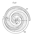
- the radius of orbital motion Ro is also illustrated in Fig. 8 as a locus of an arbitrary point Q on orbiting scroll member 30. Center of spiral element 302 is placed radially offset from an involute center of spiral element 282 of fixed scroll member 28 by the distance Ro. Thereby, orbiting scroll member 30 is allowed to make orbital motion of a radius Ro by the rotation of drive shaft 15. As the scroll member 30 orbits, line contact between both spiral elements 282, and 302 shifts to the center of spiral elements along the surface of the spiral elements.
- Circular plate 281 of fixed scroll member 28 is provided with a hole or suction port 283 which communicates between suction chambers 24 and inner chambers 29 of cylindrical housing 11.
- a hole or discharge port 284 is formed through the circular plate 281 at a position near the center of spiral element 282 and is connected to discharge chamber 25. Therefore, fluid, or refrigerant gas, introduced into chamber 29 from an external fluid circuit through inlet port 26, suction chamber 24 and hole 283 is taken into fluid pockets formed between both spiral elements 282 and 302.
- fluid in the fluid pockets is compressed. and the compressed fluid is discharged into discharge chamber 25 from the.-fluid pocket of the spiral element center through hole 284, and therefrom, discharged through an outlet port to an external fluid circuit, for example, a cooling circuit.
- Drive shaft 15, which is rotatably supported by front end plate 12 through ball bearing 14 is formed with disk portion 151.
- Disk portion 151 is rotatably supported by ball bearing 31 which is disposed in a front end opening of cylindrical housing 11.
- An inner ring of the ball bearing 31 is fitted against a collar 152 formed with disk portion 151, and other outer ring is fitted against a collar 111 formed at front end opening of cylindrical housing 11.
- An inner ring of ball bearing 14 is fitted agains a stepped portion 153 of driving shaft 15 and an outer ring of ball bearing 14 is fitted against a shoulder portion 121 of the opening of front end plate 12. Therefore, driving shaft 15, ball bearing 14 and ball bearing 31 are supported for rotation without axial motion.
- a crank pin or drive pin 154 axially projects from an end surface of disk portion 151 and, hence, from an end of drive shaft 15, and is radially offset from the center of drive shaft 15.
- Circular plate 301 of orbiting scroll member 30 is provided with a tubular boss 303 axially projecting from an end surface of the plate 301.
- the spiral element 302 extends from an opposite end surface of the circular plate 301.
- a discoid or short axial bushing 33 is fitted into boss 303, and rotatably supported therein by bearing means, such as a needle bearing 34.
- Bushing 33 has a balance weight 331 which is shaped as a portion of a disc or ring and extends radially from the bushing 33 along a front surface thereof.
- An eccentric hole 332 is formed in the bushing 33 radially offset from center of the bushing 33.
- Drive pin 154 is fitted into the eccentrically disposed hole 332 within which a bearing 32 may be applied.
- Bushing 33 is therefore driven by the revolution of drive pin 154 and permitted to rotate by the needle bearing 34.
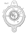
- Respective placement of center Os of shaft 15, center Oc of bushing 33, and center Od of hole 332 and thus of drive pin 154, is shown in Fig. 3.
- the distance between Os and Oc is the radius Ro of orbital motion, which is shown there for purposes of explanation, and when drive pin 154 is fitted to eccentric hole 332, center Od of drive pin 154 is placed, with respect to Os, on the opposite side of a line Ll, which is through Oc and perpendicular to a line L2 through Oc and Os, and also beyond the line through Oc and Os in direction of rotation A of shaft 15.
- This relationship of centers Os, Oc and Od holds true in all rotative positions of drive shaft 15.
- Od at this particular point of motion, is located in the upper left hand quadrant defined by the lines L1 and L2.
- center Oc of bushing 33 is permitted to swing about the center Od of drive pin 154 at a radius E2, as shown in Fig. 4.
- Such swing motion of center Oc is illustrated as are Oc'-Oc"' in Fig. 4.
- This permitted swing motion allows the orbiting scroll member 30 to compensate its motion for changes in Ro due to wear on the spiral elements.282, 302 or due to other dimensional inaccuracies of the spiral elements.
- spiral element 302 of orbiting scroll member 30 is forced toward spiral element 282 of fixed scroll member 28 and the orbiting scroll member 30 orbits with the radius Ro around center Os of drive shaft 15 of necessity.
- the rotation of orbiting scroll member 30 is prevented by a rotation preventing mechanism, described more fully hereinafter, whereby orbiting scroll member 30 orbits and keeps its relative angular relationship.
- the fluid pocket moves because of the orbital motion of orbiting scroll member 30, to thereby compress the fluid.
- reaction force Fr When fluid is compressed by orbital motion of orbiting scroll member 30, reaction force Fr, caused by the compression of the fluid, acts on spiral element 302. This reaction force Fr acts in a direction tangential to the circle of orbiting motion. This reaction force, which is shown as Fr of Fig. 4, in the final analysis, acts on center Oc of bushing 33.
- Orbiting scroll member 30 which is supported by bushing 33 is also subject to the rotating moment with radius E2 around center Od of drive pin 154 and, hence, the rotating moment is also transferred to spiral element 302.
- This moment urges spiral element 302 against spiral element 282 with an urging force Fp.
- the urging force which acts at the line contact between both spiral element 302 and 282 will be automatically derived from the reaction force whereby a seal of the fluid pockets is attained.
- center Oc of bushing 33 is rotatable around center Od of drive pin 154, therefore, if a pitch of a spiral element or a wall thickness of a spiral element, due to manufacturing inaccuracy or wear, has a dimensional error, distance Oc-Od changes to correspond the error. Orbiting scroll member 30 thereby moves smoothly along the line contacts between the spiral elements. So that, if only the urging force Fp acts on the spiral element 302 of orbiting scroll member 30 to press it against spiral 282, the center Oc swings as seen in Fig. 4, and a balance weight is not needed when the centrifugal force is not excessive.
- centrifugal force Fl can be cancelled by centrifugal force F2 of the balance weight.
- the mass of the balance weight is -selected so that the centrifugal force F2 is equal in magnitude to the centrifugal force Fl and located so that the centrifugal forces Fl and F2 are opposite in direction. Wear of both spiral elements will thereby also be decreased; the sealing force of fluid pockets, which is independent of shaft speed, will be secured by the contact between the spiral elements described in Fig. 4.
- bushing 33 is freely rotatable on the drive pin 154, so that bushing 33 is movable vertically, but if bushing 33 would be fully freely rotatable around drive pin 154, the balance weight would interfere with interior wall of the housing. Therefore, to limit the rotational movement of bushing 33 around drive pin 154, the unit is provided with a swing angle limiting means which is shown in Fig. 5.
- the swing angle limiting means is formed as a projection, such as a pin 155, from either the bushing 33 or the disk portion 151, and a reception opening for the projection, such as an arc-shaped groove 333, in the other of the bushing 33 or disk portion 15.
- Disk portion 151 of drive shaft 15 is provided with the coupling pin 155 at its end surface and bushing 33 has the arc-shaped groove 333 formed on the end surface of the disk portion 151 for receiving the pin 155.
- Groove 333 extends in an arc with its center at the center of eccentric hole 332 and a radius of the distance between drive pin 154 and pin 155. The reception of the coupling pin 155 within the groove 333 limits the amount of swing of the bushing 33 to a selected degree.
- suitable sealing force of the fluid pocket is accomplished by using bushing 33 having balance weight 331.
- a centrifugal force Fl arises due to orbiting of scroll member 30, bearing 34 and bushing 33 (except balance weight); and centrifugal force F2 arises due to orbiting of balance weight 331.
- the centrifugal forces Fl, F2 are made equal in magnitude, however, direction of the forces-is opposed. Therefore, as the acting points of. these forces are apart axially, a moment arises and vibration of the unit can occur.
- Acting point of Fl is a centroid, ie., center of mass, G30 of orbiting scroll member 30, bearing 34 and bushing 33
- acting point of F2 is a centroid G331 of balance weight 331.
- Balance weight 331, which is attached to bushing 33 and thereby coupled to orbiting scroll member 30, is axially offset from the scroll member 30. Therefore, centroid G30 is not aligned with centroid G331 in an axial direction of the shaft 15.
- the unit is provided with a cancelling mechanism which is shown in Fig. 1.
- Drive shaft 15 is provided with a pair of balance weights 35, 36.
- the balance weight 35 is placed on the shaft 15 near or adjacent to the balance weight 331 to cause a centrifugal force in the same direction as the centrifugal force of the balance weight 331.
- the balance weight 36 is placed on the shaft 15 on an opposite radial side of the drive shaft 15 as the balance weight 35 and on an opposite side in the axial direction relative to the balance weight 331. The balance weight 36 causes centrifugal force in an opposite direction to the centrifugal force of said balance weight 35.
- balance weight 35 is disposed in a counterbore 130 which is formed at the front end opening of cylindrical housing 11 and is fixed by a bolt 37 to a front end surface of disk portion 151.
- Balance weight 36 is fixed to or formed integral with a stopper plate 38 which is supported by armature 21 of the magnetic clutch.
- Centrifugal force of balance weight 35 and 36 is designated as F3 and F4, respectively, and the relation of the centrifugal forces Fl, F2, F3 and F4 is shown in Fig. 6.
- Fl-F2 so that this moment, ie., the moment created due to the axial offset of centroids G30 and G331, is defined in Fl(X 1 ), where X is distance from centroid G30 of orbiting scroll member 30, bearing 34 and bushing 33 to centroid 331 of balance weight 331 along the axis of shaft 15.
- the direction of the moment is shown by curved arrows M1 in Fig. 6 and is made up of the moments created by the forces F1 and-F2.
- Another moment is created due to the centrifugal forces created by the rotation of axially spaced balance weights 35, 36.
- This moment is shown as F3(X ) and the direction of rotation by this moment is opposed to the moment F1(X 1 ) where X2 is a distance between centroid G35 and G36 along the axis of shaft 15.
- the direction of the second moment is shown by curved arrow M2 in Fig. 6.
- Rotation preventing means 39 is disposed to surround boss 303 and is comprised of a fixed ring 391 and an Oldham ring 392. Ring 391 is secured to a stepped portion of the inner surface of cylindrical housing 11 by pin 40. Fixed ring 391 is provided with a pair of keyways 391a and 391b in an axial end surface facing orbiting scroll member 30.. Oldham ring 392 is disposed in a hollow space between fixed ring 391 and circular plate 301 of orbiting scroll member 30. Oldham ring 392 is provided with a pair of keys 392a and 392b on the surface facing fixed ring 391, which are received in keyways 391a and 391b.
- Oldham ring 392 is slidable in the radial direction by the guide of keys 392a and 392b within keyways 391a and 391b.
- Oldham ring 392 is also provided with a pair of keys 392c and 392d on its opposite surface. Keys 392c and 392d are arranged along a diameter perpendicular to the diameter along which keys 392a and 392b are arranged.
- Circular plate 301 of orbiting scroll member 30 is provided with a pair of keyways, one of which is shown as 301a in Fig. 7, on a surface facing Oldham ring 392 in which are received keys 392c and 392d.
- the ⁇ keyways of plate 301 are formed outside the diameter of boss 303. Therefore, orbiting scroll member 30 is slidable in a radial direction by guide of keys 392c and 392d within the keyways of circular plate 301.
- Oldham ring 392 reciprocates along the direction of key 392a-b or keyway 391a-b, which creates vibration due to inertia. This cannot be cancelled by the aforementioned technology, however, by making Oldham ring 392 light, the vibration can be of an acceptable level.
- orbiting scroll member 30 is slidable in one radial direction with Oldham ring 392, and is slidable in another radial direction independently.
- the second sliding direction is perpendicular to the first radial direction. Therefore, orbiting scroll member 30 is prevented from rotation, but is permitted to move in two radial directions perpendicular to one another.
- bearing elements 41 are supported in openings of Oldham ring 392, and between fixed ring 391 and circular plate 301, and therefore function as a thrust bearings for the orbiting scroll member.
Landscapes
- Engineering & Computer Science (AREA)
- Mechanical Engineering (AREA)
- General Engineering & Computer Science (AREA)
- Physics & Mathematics (AREA)
- Fluid Mechanics (AREA)
- Rotary Pumps (AREA)
Priority Applications (1)
| Application Number | Priority Date | Filing Date | Title |
|---|---|---|---|
| SG26187A SG26187G (en) | 1980-03-18 | 1987-03-13 | Balancing means for a scroll-type fluid displacement apparatus |
Applications Claiming Priority (2)
| Application Number | Priority Date | Filing Date | Title |
|---|---|---|---|
| JP55034559A JPS5819875B2 (ja) | 1980-03-18 | 1980-03-18 | スクロ−ル型圧縮機 |
| JP34559/80 | 1980-03-18 |
Related Parent Applications (2)
| Application Number | Title | Priority Date | Filing Date |
|---|---|---|---|
| EP81301155A Division EP0037658B1 (de) | 1980-03-18 | 1981-03-18 | Ausgleichsmittel für eine spiralförmige Fluidumverdrängermaschine |
| EP81301155.8 Division | 1981-03-18 |
Publications (2)
| Publication Number | Publication Date |
|---|---|
| EP0091544A2 true EP0091544A2 (de) | 1983-10-19 |
| EP0091544A3 EP0091544A3 (de) | 1984-05-02 |
Family
ID=12417662
Family Applications (2)
| Application Number | Title | Priority Date | Filing Date |
|---|---|---|---|
| EP81301155A Expired EP0037658B1 (de) | 1980-03-18 | 1981-03-18 | Ausgleichsmittel für eine spiralförmige Fluidumverdrängermaschine |
| EP83101538A Withdrawn EP0091544A3 (de) | 1980-03-18 | 1981-03-18 | Synchronisiervorrichtung für eine spiralförmige Fluidumverdrängermaschine |
Family Applications Before (1)
| Application Number | Title | Priority Date | Filing Date |
|---|---|---|---|
| EP81301155A Expired EP0037658B1 (de) | 1980-03-18 | 1981-03-18 | Ausgleichsmittel für eine spiralförmige Fluidumverdrängermaschine |
Country Status (7)
| Country | Link |
|---|---|
| US (1) | US4824346A (de) |
| EP (2) | EP0037658B1 (de) |
| JP (1) | JPS5819875B2 (de) |
| AU (1) | AU544778B2 (de) |
| CA (1) | CA1339633C (de) |
| DE (1) | DE3170580D1 (de) |
| MY (1) | MY8700533A (de) |
Cited By (5)
| Publication number | Priority date | Publication date | Assignee | Title |
|---|---|---|---|---|
| EP0236665A1 (de) * | 1986-01-10 | 1987-09-16 | Sanyo Electric Co., Ltd | Spiralverdichter |
| EP0468605A1 (de) * | 1990-07-24 | 1992-01-29 | Mitsubishi Jukogyo Kabushiki Kaisha | Spiralverdichter |
| US5199862A (en) * | 1990-07-24 | 1993-04-06 | Mitsubishi Jukogyo Kabushiki Kaisha | Scroll type fluid machinery with counter weight on drive bushing |
| US6283737B1 (en) * | 2000-06-01 | 2001-09-04 | Westinghouse Air Brake Technologies Corporation | Oiless rotary scroll air compressor antirotation assembly |
| US6302664B1 (en) * | 2000-05-31 | 2001-10-16 | Westinghouse Air Brake Company | Oilers rotary scroll air compressor axial loading support for orbiting member |
Families Citing this family (43)
| Publication number | Priority date | Publication date | Assignee | Title |
|---|---|---|---|---|
| US4934910A (en) * | 1980-10-08 | 1990-06-19 | American Standard, Inc. | Scroll-type fluid apparatus with radially compliant driving means |
| JPS6012956Y2 (ja) * | 1980-11-10 | 1985-04-25 | サンデン株式会社 | スクロ−ル型圧縮機 |
| JPS57195801A (en) * | 1981-05-27 | 1982-12-01 | Sanden Corp | Fluidic device of volute type |
| JPS5896193A (ja) * | 1981-12-03 | 1983-06-08 | Mitsubishi Heavy Ind Ltd | スクロ−ル型圧縮機 |
| JPH063192B2 (ja) * | 1982-12-08 | 1994-01-12 | 三菱電機株式会社 | スクロ−ル圧縮機 |
| JPS59120794A (ja) * | 1982-12-27 | 1984-07-12 | Mitsubishi Electric Corp | スクロ−ル圧縮機 |
| JPS59126096A (ja) * | 1982-12-29 | 1984-07-20 | Toyoda Autom Loom Works Ltd | スクロ−ル型圧縮機における回転スクロ−ル部材の駆動機構 |
| JPS59107081U (ja) * | 1983-01-10 | 1984-07-19 | 三菱重工業株式会社 | スクロ−ル型流体機械 |
| JPS59115884U (ja) * | 1983-01-26 | 1984-08-04 | 三菱重工業株式会社 | スクロ−ル型流体機械 |
| JPS59142480U (ja) * | 1983-03-15 | 1984-09-22 | サンデン株式会社 | スクロ−ル型流体装置 |
| JPS59173587A (ja) * | 1983-03-22 | 1984-10-01 | Mitsubishi Electric Corp | スクロ−ル形流体機械 |
| JPS59196745A (ja) * | 1983-03-31 | 1984-11-08 | Res Assoc Residual Oil Process<Rarop> | 鉄含有ゼオライト組成物 |
| JPS59215984A (ja) * | 1983-05-24 | 1984-12-05 | Sanden Corp | スクロ−ル型圧縮機 |
| JPS60178985A (ja) * | 1984-02-24 | 1985-09-12 | Sanden Corp | 回転数検出機能を有する圧縮機 |
| JPH0697036B2 (ja) * | 1986-05-30 | 1994-11-30 | 松下電器産業株式会社 | 電動圧縮機 |
| US5094205A (en) * | 1989-10-30 | 1992-03-10 | Billheimer James C | Scroll-type engine |
| JP2863261B2 (ja) * | 1990-05-18 | 1999-03-03 | サンデン株式会社 | スクロール型圧縮機 |
| JPH04101001A (ja) * | 1990-08-16 | 1992-04-02 | Mitsubishi Heavy Ind Ltd | スクロール型流体機械 |
| JPH0487382U (de) * | 1990-12-06 | 1992-07-29 | ||
| US5366357A (en) * | 1992-02-28 | 1994-11-22 | Kabushiki Kaisha Toyoda Jidoshokki Seisakusho | Scroll type compressor having a counterweight mounted with a clearance on a driveshaft |
| JP3106737B2 (ja) * | 1992-11-17 | 2000-11-06 | 株式会社豊田自動織機製作所 | スクロール型圧縮機 |
| US5437543A (en) * | 1992-11-26 | 1995-08-01 | Kabushiki Kaisha Toyoda Jidoshokki Seisakusho | Scroll type refrigerant compressor with means for improving airtight sealing of compression chambers |
| JPH06235385A (ja) * | 1993-02-09 | 1994-08-23 | Toyota Autom Loom Works Ltd | スクロール型圧縮機 |
| US5366360A (en) * | 1993-11-12 | 1994-11-22 | General Motors Corporation | Axial positioning limit pin for scroll compressor |
| JP2682790B2 (ja) * | 1993-12-02 | 1997-11-26 | 株式会社豊田自動織機製作所 | スクロール型圧縮機 |
| JP2740736B2 (ja) * | 1994-04-07 | 1998-04-15 | 株式会社デンソー | 圧縮機 |
| GB2320062B (en) * | 1994-07-22 | 1998-12-16 | Mitsubishi Electric Corp | Scroll compressor |
| TW381147B (en) * | 1994-07-22 | 2000-02-01 | Mitsubishi Electric Corp | Scroll compressor |
| US6273692B1 (en) * | 1999-06-29 | 2001-08-14 | Sanden Corporation | Scroll-type compressor |
| JP4153131B2 (ja) | 1999-09-14 | 2008-09-17 | サンデン株式会社 | 電動圧縮機 |
| JP2004270614A (ja) * | 2003-03-11 | 2004-09-30 | Sanden Corp | 電動圧縮機 |
| CN100434713C (zh) * | 2004-06-28 | 2008-11-19 | 乐金电子(天津)电器有限公司 | 压缩机平衡重的塞缝结构 |
| CN100408860C (zh) * | 2005-12-31 | 2008-08-06 | 西安交通大学 | 旋叶式压缩机排量自动调节机构 |
| US8459971B2 (en) * | 2008-09-26 | 2013-06-11 | Honda Motor Co., Ltd. | Scroll compressor with balancer and oil passages |
| US8147230B2 (en) * | 2009-04-06 | 2012-04-03 | Chu Henry C | Scroll compressor having rearwardly directed fluid inlet and outlet |
| JP6553968B2 (ja) | 2015-07-17 | 2019-07-31 | サンデン・オートモーティブコンポーネント株式会社 | スクロール型圧縮機 |
| WO2018019372A1 (de) * | 2016-07-27 | 2018-02-01 | Bitzer Kühlmaschinenbau Gmbh | Kompressor |
| US11193490B2 (en) | 2018-03-30 | 2021-12-07 | Kabushiki Kaisha Toyota Jidoshokki | Scroll compressor including bushing mounted on eccentric shaft containing cylindrical and auxiliary weight portions and balancer disposed above annular rotor remote from back pressure chamber |
| JP2020165394A (ja) * | 2019-03-29 | 2020-10-08 | 株式会社豊田自動織機 | スクロール型電動圧縮機 |
| DE102020121442B4 (de) | 2020-08-14 | 2023-01-05 | OET GmbH | Ausgleichsmechanismus für Scrollverdichter |
| CN112610486B (zh) * | 2020-12-03 | 2022-09-30 | 珠海格力节能环保制冷技术研究中心有限公司 | 一种偏心量调节机构及涡旋压缩机 |
| DE102022104746A1 (de) * | 2022-02-28 | 2023-08-31 | OET GmbH | Ausgleichsmechanismus für eine Verdrängermaschine |
| DE102022119370A1 (de) | 2022-08-02 | 2024-02-08 | OET GmbH | Verfahren zum Wuchten einer beweglichen Baugruppe einer Verdrängermaschine |
Family Cites Families (14)
| Publication number | Priority date | Publication date | Assignee | Title |
|---|---|---|---|---|
| US801182A (en) * | 1905-06-26 | 1905-10-03 | Leon Creux | Rotary engine. |
| US1906142A (en) * | 1930-04-02 | 1933-04-25 | Ekelof John | Rotary pump or compressor |
| GB486192A (en) * | 1936-11-26 | 1938-05-31 | Cfcmug | Improvements in apparatus for fluids such as engines, pumps, compressors, meters andthe like, comprising a member operated by an orbitary movement |
| GB1255799A (en) * | 1967-12-18 | 1971-12-01 | Krauss Maffei Ag | Rotary positive fluid displacement apparatus |
| US3924977A (en) * | 1973-06-11 | 1975-12-09 | Little Inc A | Positive fluid displacement apparatus |
| US3884599A (en) * | 1973-06-11 | 1975-05-20 | Little Inc A | Scroll-type positive fluid displacement apparatus |
| US3874827A (en) * | 1973-10-23 | 1975-04-01 | Niels O Young | Positive displacement scroll apparatus with axially radially compliant scroll member |
| US3994636A (en) * | 1975-03-24 | 1976-11-30 | Arthur D. Little, Inc. | Axial compliance means with radial sealing for scroll-type apparatus |
| US3994633A (en) * | 1975-03-24 | 1976-11-30 | Arthur D. Little, Inc. | Scroll apparatus with pressurizable fluid chamber for axial scroll bias |
| US3994635A (en) * | 1975-04-21 | 1976-11-30 | Arthur D. Little, Inc. | Scroll member and scroll-type apparatus incorporating the same |
| US3986799A (en) * | 1975-11-03 | 1976-10-19 | Arthur D. Little, Inc. | Fluid-cooled, scroll-type, positive fluid displacement apparatus |
| US4065279A (en) * | 1976-09-13 | 1977-12-27 | Arthur D. Little, Inc. | Scroll-type apparatus with hydrodynamic thrust bearing |
| US4082484A (en) * | 1977-01-24 | 1978-04-04 | Arthur D. Little, Inc. | Scroll-type apparatus with fixed throw crank drive mechanism |
| BE870198A (fr) * | 1978-09-05 | 1979-03-05 | Little Inc A | Elements en volute complementaires, notamment pour pompes a liquides |
-
1980
- 1980-03-18 JP JP55034559A patent/JPS5819875B2/ja not_active Expired
-
1981
- 1981-03-17 CA CA000373169A patent/CA1339633C/en not_active Expired - Lifetime
- 1981-03-18 AU AU68495/81A patent/AU544778B2/en not_active Expired
- 1981-03-18 US US06/244,961 patent/US4824346A/en not_active Expired - Lifetime
- 1981-03-18 EP EP81301155A patent/EP0037658B1/de not_active Expired
- 1981-03-18 DE DE8181301155T patent/DE3170580D1/de not_active Expired
- 1981-03-18 EP EP83101538A patent/EP0091544A3/de not_active Withdrawn
-
1987
- 1987-12-30 MY MY533/87U patent/MY8700533A/xx unknown
Cited By (6)
| Publication number | Priority date | Publication date | Assignee | Title |
|---|---|---|---|---|
| EP0236665A1 (de) * | 1986-01-10 | 1987-09-16 | Sanyo Electric Co., Ltd | Spiralverdichter |
| EP0468605A1 (de) * | 1990-07-24 | 1992-01-29 | Mitsubishi Jukogyo Kabushiki Kaisha | Spiralverdichter |
| AU634059B2 (en) * | 1990-07-24 | 1993-02-11 | Mitsubishi Jukogyo Kabushiki Kaisha | Scroll type fluid machine |
| US5199862A (en) * | 1990-07-24 | 1993-04-06 | Mitsubishi Jukogyo Kabushiki Kaisha | Scroll type fluid machinery with counter weight on drive bushing |
| US6302664B1 (en) * | 2000-05-31 | 2001-10-16 | Westinghouse Air Brake Company | Oilers rotary scroll air compressor axial loading support for orbiting member |
| US6283737B1 (en) * | 2000-06-01 | 2001-09-04 | Westinghouse Air Brake Technologies Corporation | Oiless rotary scroll air compressor antirotation assembly |
Also Published As
| Publication number | Publication date |
|---|---|
| EP0091544A3 (de) | 1984-05-02 |
| EP0037658A1 (de) | 1981-10-14 |
| JPS5819875B2 (ja) | 1983-04-20 |
| AU544778B2 (en) | 1985-06-13 |
| CA1339633C (en) | 1998-01-20 |
| JPS56129791A (en) | 1981-10-12 |
| MY8700533A (en) | 1987-12-31 |
| DE3170580D1 (en) | 1985-06-27 |
| US4824346A (en) | 1989-04-25 |
| EP0037658B1 (de) | 1985-05-22 |
| AU6849581A (en) | 1981-09-24 |
Similar Documents
| Publication | Publication Date | Title |
|---|---|---|
| EP0037658B1 (de) | Ausgleichsmittel für eine spiralförmige Fluidumverdrängermaschine | |
| CA1222982A (en) | Scroll-type fluid compressor | |
| EP0078148B1 (de) | Vorgespannte Antriebseinrichtung für kreisendes, fluidverdrängendes Maschinenteil | |
| US4406600A (en) | Scroll-type fluid displacement apparatus with rotation prevention/thrust bearing means for orbiting scroll member | |
| EP0059925B1 (de) | Antriebsmittel für eine Fluidumverdrängungsanlage mit Exzenterspiralelementen | |
| US4597724A (en) | Scroll type fluid displacement apparatus with centrifugal force balanceweight | |
| EP0061698A1 (de) | Vorrichtung mit kreisendem Kolben zum Fördern von Fluiden, mit einer Einrichtung zum Verhindern der Rotation | |
| EP0052461B1 (de) | Fluidumverdrängeranlage mit Exzenterschneckenelementen und Mitteln zum Entgegenwirken von Fliehkräften | |
| EP0060495B1 (de) | Rotationsverhinderungseinrichtung für eine Kreiskolben-Fluidumanlage | |
| CA1278782C (en) | Axial thrust load mechanism for a scroll type fluid displacement apparatus | |
| US4645435A (en) | Rotation preventing device for an orbiting member of a fluid displacement apparatus | |
| EP0061064B1 (de) | Kreiskolben-Fluidumverdrängungsanlage mit Mitteln zur Rotationsverhinderung | |
| EP0078128B1 (de) | Stützenlager für Fluidumverdrängungsmaschine | |
| EP0123407B1 (de) | Einrichtung zum Verhindern der Rotation für eine Verdrängermaschine mit kreisendem Kolben | |
| US4411604A (en) | Scroll-type fluid displacement apparatus with cup shaped casing | |
| AU636650B2 (en) | Orbiting member fluid displacement apparatus with rotation preventing mechanism | |
| CA1222984A (en) | Drive shaft support means for fluid displacement apparatus | |
| GB2142980A (en) | Scroll-type rotary positive-displacement fluid-machine | |
| EP0077212B1 (de) | Riemenscheibenantrieb für Fluidumverdrängungsmaschine | |
| CA1282754C (en) | Scroll type fluid displacement apparatus with centrifugal force balanceweight | |
| GB2167131A (en) | Scroll-type rotary fluid-machine |
Legal Events
| Date | Code | Title | Description |
|---|---|---|---|
| PUAI | Public reference made under article 153(3) epc to a published international application that has entered the european phase |
Free format text: ORIGINAL CODE: 0009012 |
|
| AC | Divisional application: reference to earlier application |
Ref document number: 37658 Country of ref document: EP |
|
| AK | Designated contracting states |
Designated state(s): DE FR GB IT SE |
|
| PUAL | Search report despatched |
Free format text: ORIGINAL CODE: 0009013 |
|
| AK | Designated contracting states |
Designated state(s): DE FR GB IT SE |
|
| 17P | Request for examination filed |
Effective date: 19841029 |
|
| STAA | Information on the status of an ep patent application or granted ep patent |
Free format text: STATUS: THE APPLICATION IS DEEMED TO BE WITHDRAWN |
|
| 18D | Application deemed to be withdrawn |
Effective date: 19870414 |
|
| RIN1 | Information on inventor provided before grant (corrected) |
Inventor name: SAKAMOTO, SEIICHI Inventor name: TERAUCHI, KIYOSHI Inventor name: MIYAZAWA, KIYOSHI Inventor name: HIRAGA, MASAHARU |