EP0091607A2 - Dispositif de sécurité pour éléments de fermeture mobiles, en particulier pour volets de protection de machines d'usinage - Google Patents
Dispositif de sécurité pour éléments de fermeture mobiles, en particulier pour volets de protection de machines d'usinage Download PDFInfo
- Publication number
- EP0091607A2 EP0091607A2 EP83103144A EP83103144A EP0091607A2 EP 0091607 A2 EP0091607 A2 EP 0091607A2 EP 83103144 A EP83103144 A EP 83103144A EP 83103144 A EP83103144 A EP 83103144A EP 0091607 A2 EP0091607 A2 EP 0091607A2
- Authority
- EP
- European Patent Office
- Prior art keywords
- closing part
- movable
- safety device
- movable closing
- sensor
- Prior art date
- Legal status (The legal status is an assumption and is not a legal conclusion. Google has not performed a legal analysis and makes no representation as to the accuracy of the status listed.)
- Granted
Links
Images


Classifications
-
- F—MECHANICAL ENGINEERING; LIGHTING; HEATING; WEAPONS; BLASTING
- F16—ENGINEERING ELEMENTS AND UNITS; GENERAL MEASURES FOR PRODUCING AND MAINTAINING EFFECTIVE FUNCTIONING OF MACHINES OR INSTALLATIONS; THERMAL INSULATION IN GENERAL
- F16P—SAFETY DEVICES IN GENERAL; SAFETY DEVICES FOR PRESSES
- F16P3/00—Safety devices acting in conjunction with the control or operation of a machine; Control arrangements requiring the simultaneous use of two or more parts of the body
- F16P3/12—Safety devices acting in conjunction with the control or operation of a machine; Control arrangements requiring the simultaneous use of two or more parts of the body with means, e.g. feelers, which in case of the presence of a body part of a person in or near the danger zone influence the control or operation of the machine
- F16P3/16—Safety devices acting in conjunction with the control or operation of a machine; Control arrangements requiring the simultaneous use of two or more parts of the body with means, e.g. feelers, which in case of the presence of a body part of a person in or near the danger zone influence the control or operation of the machine with feeling members moved by the machine
-
- B—PERFORMING OPERATIONS; TRANSPORTING
- B23—MACHINE TOOLS; METAL-WORKING NOT OTHERWISE PROVIDED FOR
- B23Q—DETAILS, COMPONENTS, OR ACCESSORIES FOR MACHINE TOOLS, e.g. ARRANGEMENTS FOR COPYING OR CONTROLLING; MACHINE TOOLS IN GENERAL CHARACTERISED BY THE CONSTRUCTION OF PARTICULAR DETAILS OR COMPONENTS; COMBINATIONS OR ASSOCIATIONS OF METAL-WORKING MACHINES, NOT DIRECTED TO A PARTICULAR RESULT
- B23Q11/00—Accessories fitted to machine tools for keeping tools or parts of the machine in good working condition or for cooling work; Safety devices specially combined with or arranged in, or specially adapted for use in connection with, machine tools
- B23Q11/08—Protective coverings for parts of machine tools; Splash guards
-
- E—FIXED CONSTRUCTIONS
- E05—LOCKS; KEYS; WINDOW OR DOOR FITTINGS; SAFES
- E05F—DEVICES FOR MOVING WINGS INTO OPEN OR CLOSED POSITION; CHECKS FOR WINGS; WING FITTINGS NOT OTHERWISE PROVIDED FOR, CONCERNED WITH THE FUNCTIONING OF THE WING
- E05F15/00—Power-operated mechanisms for wings
- E05F15/40—Safety devices, e.g. detection of obstructions or end positions
- E05F15/42—Detection using safety edges
- E05F15/47—Detection using safety edges responsive to changes in fluid pressure
-
- F—MECHANICAL ENGINEERING; LIGHTING; HEATING; WEAPONS; BLASTING
- F16—ENGINEERING ELEMENTS AND UNITS; GENERAL MEASURES FOR PRODUCING AND MAINTAINING EFFECTIVE FUNCTIONING OF MACHINES OR INSTALLATIONS; THERMAL INSULATION IN GENERAL
- F16P—SAFETY DEVICES IN GENERAL; SAFETY DEVICES FOR PRESSES
- F16P3/00—Safety devices acting in conjunction with the control or operation of a machine; Control arrangements requiring the simultaneous use of two or more parts of the body
- F16P3/08—Safety devices acting in conjunction with the control or operation of a machine; Control arrangements requiring the simultaneous use of two or more parts of the body in connection with the locking of doors, covers, guards, or like members giving access to moving machine parts
-
- F—MECHANICAL ENGINEERING; LIGHTING; HEATING; WEAPONS; BLASTING
- F16—ENGINEERING ELEMENTS AND UNITS; GENERAL MEASURES FOR PRODUCING AND MAINTAINING EFFECTIVE FUNCTIONING OF MACHINES OR INSTALLATIONS; THERMAL INSULATION IN GENERAL
- F16P—SAFETY DEVICES IN GENERAL; SAFETY DEVICES FOR PRESSES
- F16P3/00—Safety devices acting in conjunction with the control or operation of a machine; Control arrangements requiring the simultaneous use of two or more parts of the body
- F16P3/12—Safety devices acting in conjunction with the control or operation of a machine; Control arrangements requiring the simultaneous use of two or more parts of the body with means, e.g. feelers, which in case of the presence of a body part of a person in or near the danger zone influence the control or operation of the machine
-
- E—FIXED CONSTRUCTIONS
- E05—LOCKS; KEYS; WINDOW OR DOOR FITTINGS; SAFES
- E05Y—INDEXING SCHEME ASSOCIATED WITH SUBCLASSES E05D AND E05F, RELATING TO CONSTRUCTION ELEMENTS, ELECTRIC CONTROL, POWER SUPPLY, POWER SIGNAL OR TRANSMISSION, USER INTERFACES, MOUNTING OR COUPLING, DETAILS, ACCESSORIES, AUXILIARY OPERATIONS NOT OTHERWISE PROVIDED FOR, APPLICATION THEREOF
- E05Y2999/00—Subject-matter not otherwise provided for in this subclass
Definitions
- the invention relates to a safety device on movable locking parts, in particular on protective flaps of machine tools, primarily in the manufacture of body parts of motor vehicles, the locking part on its free edge carrying an air-filled hose (contact strip) as a sensor, which works as a pressure wave transmitter and controls a locking and / or reversing device for the closing part movement.
- an air-filled hose contact strip
- Safety devices of the aforementioned type have become known from DE-AS'n 21 27 207 and 28 39 498 and DE-DS'n 26 43 505, 26 58 660 and 27 12 173.
- the "movable locking parts", for which the safety devices are provided in accordance with the above-mentioned documents, are each doors, eg. 8. on vehicles or gates, these doors or gates automatically closing and opening.
- the safety devices of the type in question are intended to prevent unintentional jamming of objects or people between the closing door or gate leaves.
- the safety devices each work in such a way that when the pinching process begins, the sensor (pneumatic pressure wave transmitter) emits a pressure pulse to a control device, which then causes the door or gate to be reopened immediately.
- the movable locking parts are mostly designed as protective flaps and have the purpose of preventing the operator from accessing the workpiece during the machining thereof in order to avoid possible injury to the operator.
- the protective flap moves into its closed position when a simple start button is pressed, and the actual working cycle of the processing machine is initiated. At the end of the work sequence, the protective flap is moved back to the starting position.
- the lower edge of the protective flap has a sensor which acts as a pressure wave transmitter and which, in the event of being caught, supplies the pneumatic signal required to activate the safety device.
- the damper is immediately efahren in such a case back upwards g.
- the problem is solved in that a mechanical test element is arranged on a first section of the travel path of the movable closing part, such that the sensor (contact strip) at the beginning of the closing stroke (within the test section) of the movable closing part with the mechanical test element in Contact comes in such a way that the sensor generates a first pressure pulse and that the drive of the movable closing part is controlled so that when the first pressure pulse is absent on the first section (test section) of the closing stroke, the closing movement of the movable closing part is interrupted.
- the movable closing part eg. B. a downward flap of a sheet metal machine, so to speak Baffled in the way, which in turn now checks whether the pressure wave transmitter works.
- a protective flap with a defective sensor pressure wave encoder therefore does not perform a closing movement.
- the double safety created by the invention advantageously enables the use of such automatically working protective flaps on machine tools of any kind, in particular also on sheet metal working machines in automobile construction, without the risk of injury to the operating personnel having to be feared more.
- the invention is also equally applicable to all other conceivable safety devices in which people or objects have to be protected from being pinched by movable locking parts (e.g. automatically closing doors or gates and the like).
- the mechanical test element according to the invention is characterized by very low technical and cost expenditure.
- the control system also processes the first pressure wave pulse caused by the mechanical test element the Schlißteilantriebes can be easily realized in practice.
- the drive of the movable closing part within the test section that is to say at the beginning of the closing stroke, is controlled via the holding circuit of a relay, in such a way that when the first pressure pulse is generated by the pressure wave generator trained sensor (contact strip) the movement of the closing part directed in the closing direction is not interrupted.
- test section determined by the arrangement and design of the mechanical test element is expediently 50 mm or approximately 50 mm.
- the control of the drive of the movable closing part should be designed in such a way that after the interruption of the closing movement if the first pressure pulse is absent, the movable closing part is reset to its initial position.
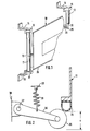
- the movable closing part is a protective flap, designated overall by 10, which - e.g. B. on machines for sheet metal working in the automotive industry - to protect the operator from possible injuries.
- Pneumatic cylinders 11, 12 are arranged on both sides of the protective flap 10, inside each of which a compressed air-actuated piston (not shown), which has no piston rod, can be moved up and down.
- Such pneumatic cylinders which are commercially available, can save expensive guides for the protective flap 10. As a result, the overall manufacturing costs for the protective device can be kept low.
- the pistons of the pneumatic cylinders 11, 12 each engage the protective flap 10 through a fastening part 13 or 14.
- angle iron 15 Fig. 1
- a pressure line system provided for this purpose is designated 18, 19. It is - as indicated by an arrow 20 - (not shown) of a g eeig- Neten source of compressed air supplied.
- the line of the pressure line system, numbered 18, leads to the upper ones Ends 16 of the pneumatic cylinders 11, 12 and causes a downward movement of the pistons or the protective flap 10 connected to them.
- the line line 19 leading to the lower ends 17 of the pneumatic cylinders 11, 12 accordingly causes an upward movement of the pistons and thus also the protective flap 10 .
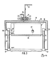
- a compressed air valve schematically indicated in FIGS. 3 and 4 and altogether numbered 21, is connected.
- the compressed air valve 21 In the position shown in FIGS. 3 and 4, the compressed air valve 21 is in the blocking position, i. H. no compressed air can get into the power system 18, 19.
- the compressed air valve 21 also has two possible operating positions, which are symbolized in FIGS. 3 and 4 by boxes 22, 23.
- the other operating position designated 23 on the other hand, compressed air enters the line 19, while the line 18 is now vented. This valve position is required to cause the protective flap to move upwards.
- an electrical control system shown in simplified form in FIG. 4 as a rectangular block and designated overall by 25, is used (cf. also FIG. 5 and explanations below).
- a contact strip 26 is arranged on the lower edge of the protective flap 10 and is designed as a closed air-filled hose.
- a pressure wave switch 27 is included in the self-contained air system of the contact strip 26 (cf. FIG. 4). The connection between the parts 26, 27 is established here by a line 28. The pressure wave switch 27 be sits an air chamber 30 which is closed off by a membrane 29 and into which the line 28 opens. A switching element 31 is attached to the membrane 29 and engages an electrical switch 32. The pressure wave switch 27 is in electrical operative connection with the controller 25 by means of contacts 33 and an electrical line 34.
- an obstacle for example, an operator's hand
- a test roller 35 is arranged as a mechanical test element below the contact strip 26 (based on its upper end position).
- the test roller 35 is mounted on the free end of a lever arm 36, which is articulated at 37 on the machine frame or another suitable fixed part 38.
- Lever arm 36 and test roller 35 are - as can be seen in particular from FIG. 2 - held in their ready position by a tension spring 39.
- test roller 35 is arranged in such a way that the contact strip 25 comes into contact with it during a first section of the downward stroke of the protective flap 10, hereinafter referred to as the “test section”.
- the test section is illustrated in FIG. 2 by a double arrow labeled a and is approximately 50 mm.
- an actuating rail 40 is fastened to the protective flap 10 and cooperates with a limit switch 41.
- the limit switch 41 is operatively connected to the controller 25 by an electrical line 42. It has a rollenförmi g it feeler element 43, which rolls on the balance rail 40, while the damper 10 performs its downward movement.
- the effective length of the actuating rail 40 in turn corresponds to the amount a of the test section (vol. Fig. 2). As long as the roller-shaped sensing element 43 rolls on the actuating rail 40, the limit switch 41 is activated.
- the signal he entered into the control 25 has the effect that the reversal effect (in the sense of a reversal of the closing part drive 16-21) caused when the pressure wave switch 27 is actuated in the control 25 is canceled again by the limit switch 41 in the region of the test section a.
- the signal is accordingly processed by the controller 25 so that the protective flap 10 continues its downward movement.
- the controller 25 is activated by the activated limit switch 41 to reverse the protective flap drive 16 to 21 (item 23 of the compressed air valve 21).
- the protective flap 10 is thereby stopped in its downward movement and moved back up to its starting position (FIGS. 3 and 4).
- test roller 35 and contact strip 26 as well as limit switches 41, 43 and actuating rail 40 come out of engagement at the same time. From this point on, the limit switch 41 is no longer in electrical connection with the control 25.
- the contact strip 26 now encounters a natural obstacle, e.g. B. the hand of the operator, this obstacle on the contact strip 26 working as a sensor generates a pressure pulse again, which is converted by the pressure wave switch 27 in the manner described above into an electrical signal for the controller 25. In the absence of a simultaneous signal from the limit switch 41, this signal is processed by the controller 25 in such a way that the protective flap drive 16 to 21 is reversed in the sense of initiating an upward movement of the protective flap 10 (item 23 of the compressed air valve 21).
- control 25 The mode of operation of the control 25 will be explained in more detail below with reference to the circuit diagram shown in FIG. 5.
- the starting position of the device is characterized by an open protective flap 10 (uppermost protective flap position according to FIGS. 3 and 4) and the actuated limit switch 41.
- a circuit 46 closed in this way pulls in relays 47, 48 and 49.
- a switching contact 50 assigned to relay 47 in the starter circuit 51 this closes.
- the start is now - as described above b 2 - initiated by (automatic) actuation of the start button 44.
- the starter circuit 51 is now closed and causes a relay 52 to be pulled in and a switching contact 53 is subsequently closed.
- a relay 56 is hereby actuated via switching contacts 54 and 55.
- the protective flap 10 begins its downward movement.
- the relay 57 has picked up and the protective flap 10 can complete its closing movement. After completion of the work cycle, the starting conditions specified above are then canceled.
Landscapes
- Engineering & Computer Science (AREA)
- General Engineering & Computer Science (AREA)
- Mechanical Engineering (AREA)
- Physics & Mathematics (AREA)
- Fluid Mechanics (AREA)
- Power-Operated Mechanisms For Wings (AREA)
- Operating, Guiding And Securing Of Roll- Type Closing Members (AREA)
Applications Claiming Priority (2)
| Application Number | Priority Date | Filing Date | Title |
|---|---|---|---|
| DE3213491 | 1982-04-10 | ||
| DE3213491A DE3213491C1 (de) | 1982-04-10 | 1982-04-10 | Sicherheitseinrichtung an beweglichen Schliessteilen,insbesondere an Schutzklappen von Bearbeitungsmaschinen |
Publications (3)
| Publication Number | Publication Date |
|---|---|
| EP0091607A2 true EP0091607A2 (fr) | 1983-10-19 |
| EP0091607A3 EP0091607A3 (en) | 1985-08-21 |
| EP0091607B1 EP0091607B1 (fr) | 1987-06-03 |
Family
ID=6160769
Family Applications (1)
| Application Number | Title | Priority Date | Filing Date |
|---|---|---|---|
| EP83103144A Expired EP0091607B1 (fr) | 1982-04-10 | 1983-03-30 | Dispositif de sécurité pour éléments de fermeture mobiles, en particulier pour volets de protection de machines d'usinage |
Country Status (3)
| Country | Link |
|---|---|
| EP (1) | EP0091607B1 (fr) |
| DE (2) | DE3213491C1 (fr) |
| ES (1) | ES520863A0 (fr) |
Cited By (6)
| Publication number | Priority date | Publication date | Assignee | Title |
|---|---|---|---|---|
| DE3636596A1 (de) * | 1986-10-28 | 1988-05-05 | Huegle Pfullendorf Kipptor | Vorrichtung und verfahren zur absicherung von kraftbetaetigten toren, tueren, fenster insbesondere von garagentoren |
| EP0254038A3 (en) * | 1986-07-23 | 1988-06-08 | Messerschmitt-Bolkow-Blohm Gesellschaft Mit Beschrankter Haftung | Safety device for a door system |
| DE29809087U1 (de) * | 1998-05-21 | 1998-08-27 | Gerhardt, Roland, 35759 Driedorf | Automatische Maschinen- und Anlagen Schutztüren |
| WO2004022895A1 (fr) * | 2002-09-05 | 2004-03-18 | Intier Automotive Closures Inc. | Systeme d'ouverture/fermeture a touche unique pour leve-glaces electriques, cloisons et panneaux de toit |
| CN113275474A (zh) * | 2021-04-16 | 2021-08-20 | 周欣研 | 防护性强的一体化船舶板材制造用传送机构 |
| CN117381438A (zh) * | 2023-10-17 | 2024-01-12 | 嘉兴凯骐智能机械有限公司 | 一种带防护结构的多轴多工位水车加工机 |
Families Citing this family (6)
| Publication number | Priority date | Publication date | Assignee | Title |
|---|---|---|---|---|
| DE3827909C2 (de) * | 1988-08-17 | 1998-04-09 | Peter Heinrichs | Motorangetriebene Schutzscheibe für die Arbeitsplatzsicherung, insbesondere an Fließbandbetriebspunkten oder Press-, Stanz- und Schweißanlagen |
| DE4134559C2 (de) * | 1991-10-19 | 1995-11-02 | Daimler Benz Ag | Rampe für einen Türeinstieg |
| GB9508208D0 (en) * | 1995-04-22 | 1995-06-07 | Yamazaki Machinery Uk Limited | Improvements in and relating to machine tools |
| DE19642204C2 (de) * | 1996-10-12 | 1999-07-22 | Telegaertner Geraetebau Gmbh | Sicherheitseinrichtung an Umformmaschinen |
| DE102017220051B4 (de) * | 2017-11-10 | 2019-07-11 | Schäfer Werkzeug- und Sondermaschinenbau GmbH | Pneumatische Feder mit Spezialventil, Bearbeitungsvorrichtung und Verfahren |
| DE102019102004B3 (de) * | 2019-01-28 | 2020-06-10 | Pilz Gmbh & Co. Kg | Verbessertes Zugangsabsicherungssystem zum Absichern einer Maschine oder Anlage |
Family Cites Families (4)
| Publication number | Priority date | Publication date | Assignee | Title |
|---|---|---|---|---|
| FR1260115A (fr) * | 1960-03-23 | 1961-05-05 | Perfectionnement apporté aux rideaux protecteurs de machines-outils | |
| DE2307375A1 (de) * | 1973-02-15 | 1974-09-05 | Metallwaren U Maschinenfabrik | Schutzvorrichtung fuer pressen, stanzen od. dgl |
| CH596421A5 (fr) * | 1975-08-25 | 1978-03-15 | Landert Motoren Ag | |
| CH625605A5 (fr) * | 1976-10-02 | 1981-09-30 | Sick Optik Elektronik Erwin |
-
1982
- 1982-04-10 DE DE3213491A patent/DE3213491C1/de not_active Expired
-
1983
- 1983-03-23 ES ES83520863A patent/ES520863A0/es active Granted
- 1983-03-30 EP EP83103144A patent/EP0091607B1/fr not_active Expired
- 1983-03-30 DE DE8383103144T patent/DE3371937D1/de not_active Expired
Cited By (6)
| Publication number | Priority date | Publication date | Assignee | Title |
|---|---|---|---|---|
| EP0254038A3 (en) * | 1986-07-23 | 1988-06-08 | Messerschmitt-Bolkow-Blohm Gesellschaft Mit Beschrankter Haftung | Safety device for a door system |
| DE3636596A1 (de) * | 1986-10-28 | 1988-05-05 | Huegle Pfullendorf Kipptor | Vorrichtung und verfahren zur absicherung von kraftbetaetigten toren, tueren, fenster insbesondere von garagentoren |
| DE29809087U1 (de) * | 1998-05-21 | 1998-08-27 | Gerhardt, Roland, 35759 Driedorf | Automatische Maschinen- und Anlagen Schutztüren |
| WO2004022895A1 (fr) * | 2002-09-05 | 2004-03-18 | Intier Automotive Closures Inc. | Systeme d'ouverture/fermeture a touche unique pour leve-glaces electriques, cloisons et panneaux de toit |
| CN113275474A (zh) * | 2021-04-16 | 2021-08-20 | 周欣研 | 防护性强的一体化船舶板材制造用传送机构 |
| CN117381438A (zh) * | 2023-10-17 | 2024-01-12 | 嘉兴凯骐智能机械有限公司 | 一种带防护结构的多轴多工位水车加工机 |
Also Published As
| Publication number | Publication date |
|---|---|
| ES8401597A1 (es) | 1983-12-16 |
| EP0091607A3 (en) | 1985-08-21 |
| DE3213491C1 (de) | 1983-07-21 |
| EP0091607B1 (fr) | 1987-06-03 |
| ES520863A0 (es) | 1983-12-16 |
| DE3371937D1 (en) | 1987-07-09 |
Similar Documents
| Publication | Publication Date | Title |
|---|---|---|
| EP0902158B1 (fr) | Dispositif de sécurité pour dispositifs entraínés par moteur | |
| DE19506994C2 (de) | Verfahren zum Steuern einer Bewegung eines Fensters | |
| DE3618692C2 (fr) | ||
| EP0091607B1 (fr) | Dispositif de sécurité pour éléments de fermeture mobiles, en particulier pour volets de protection de machines d'usinage | |
| DE3514223A1 (de) | Verfahren und vorrichtung zum abschalten oder umsteuern eines motors fuer den antrieb eines bewegbaren oeffnungsverschlusses wie fensterscheibe, schiebedach od.dgl., insbesondere an einem kraftfahrzeug | |
| EP1258667A2 (fr) | Dispositif de protection pour machines telles que presses-plieuses, découpeuses, machines à éstamper ou analogues | |
| DE19739543A1 (de) | Sicherheitseinrichtung für motorisch angetriebene Tore | |
| DE3709592A1 (de) | Schnellauftor | |
| EP3291930B1 (fr) | Machine de traitement de fil métallique présentant un dispositif de protection | |
| CH660507A5 (de) | Vorrichtung zum betaetigen einer schiebetuer. | |
| DE19500844B4 (de) | Türantrieb | |
| DE1411651A1 (de) | Drahtverpackungsmaschine | |
| DE19847080A1 (de) | Einklemmschutzsystem | |
| DE3416546A1 (de) | Sicherheitsvorrichtung zum anhalten motorisch bewegter gegenstaende | |
| EP0191730B1 (fr) | Dispositif actionneur de porte pour l'ouverture et la fermeture automatique d'une porte | |
| DE2649629A1 (de) | Antrieb mit unfallverhuetungseinrichtung fuer tore und dgl. | |
| DE19949329C2 (de) | Schnellauftor | |
| EP2444585A2 (fr) | Procédé de surveillance de mouvements sur un portail roulant et dispositif d'exécution du procédé | |
| DE3444213C2 (de) | Sicherheitssteuerung für ein zwischen zwei Endlagen durch Kraftbetätigung hin- und herbewegliches Tor | |
| EP1048812B1 (fr) | Méthode pour normaliser la position de la vitre d'un lève-vitre de véhicule actionné par une force exterieure | |
| DE3105867C2 (de) | Schaltungsanordnung für druckmittelbetätigte, insbesondere pneumatisch betätigte, Türen in Fahrzeugen, wie Omnibussen, Straßenbahnen o.dgl. | |
| EP3153647A1 (fr) | Dispositif et procede d'actionnement d'une poignee de porte | |
| DE4432955A1 (de) | Verfahren zum Betreiben eines elektromotorischen Fensterhebers für ein Kraftfahrzeug | |
| DE102020213589B4 (de) | Verfahren zum Steuern einer vorzugsweise elektrischen Schiebetür | |
| DE3710253A1 (de) | Seilwinde fuer wahlweisen hub-, senk- und zyklischen freifall-schlagbetrieb |
Legal Events
| Date | Code | Title | Description |
|---|---|---|---|
| PUAI | Public reference made under article 153(3) epc to a published international application that has entered the european phase |
Free format text: ORIGINAL CODE: 0009012 |
|
| AK | Designated contracting states |
Designated state(s): DE FR GB IT NL SE |
|
| 17P | Request for examination filed |
Effective date: 19840224 |
|
| PUAL | Search report despatched |
Free format text: ORIGINAL CODE: 0009013 |
|
| AK | Designated contracting states |
Designated state(s): DE FR GB IT NL SE |
|
| 17Q | First examination report despatched |
Effective date: 19860512 |
|
| ITF | It: translation for a ep patent filed | ||
| GRAA | (expected) grant |
Free format text: ORIGINAL CODE: 0009210 |
|
| AK | Designated contracting states |
Kind code of ref document: B1 Designated state(s): DE FR GB IT NL SE |
|
| REF | Corresponds to: |
Ref document number: 3371937 Country of ref document: DE Date of ref document: 19870709 |
|
| ET | Fr: translation filed | ||
| PLBE | No opposition filed within time limit |
Free format text: ORIGINAL CODE: 0009261 |
|
| STAA | Information on the status of an ep patent application or granted ep patent |
Free format text: STATUS: NO OPPOSITION FILED WITHIN TIME LIMIT |
|
| 26N | No opposition filed | ||
| PG25 | Lapsed in a contracting state [announced via postgrant information from national office to epo] |
Ref country code: DE Effective date: 19881201 |
|
| PG25 | Lapsed in a contracting state [announced via postgrant information from national office to epo] |
Ref country code: GB Effective date: 19890330 |
|
| GBPC | Gb: european patent ceased through non-payment of renewal fee | ||
| PGFP | Annual fee paid to national office [announced via postgrant information from national office to epo] |
Ref country code: SE Payment date: 19900213 Year of fee payment: 8 |
|
| PGFP | Annual fee paid to national office [announced via postgrant information from national office to epo] |
Ref country code: FR Payment date: 19900221 Year of fee payment: 8 |
|
| ITTA | It: last paid annual fee | ||
| PGFP | Annual fee paid to national office [announced via postgrant information from national office to epo] |
Ref country code: NL Payment date: 19900331 Year of fee payment: 8 |
|
| PG25 | Lapsed in a contracting state [announced via postgrant information from national office to epo] |
Ref country code: SE Effective date: 19910331 |
|
| PG25 | Lapsed in a contracting state [announced via postgrant information from national office to epo] |
Ref country code: NL Effective date: 19911001 |
|
| NLV4 | Nl: lapsed or anulled due to non-payment of the annual fee | ||
| PG25 | Lapsed in a contracting state [announced via postgrant information from national office to epo] |
Ref country code: FR Effective date: 19911129 |
|
| REG | Reference to a national code |
Ref country code: FR Ref legal event code: ST |
|
| EUG | Se: european patent has lapsed |
Ref document number: 83103144.8 Effective date: 19911009 |