EP0091812A1 - Tête pour la reproduction d'enregistrements magnétiques perpendiculaires - Google Patents
Tête pour la reproduction d'enregistrements magnétiques perpendiculaires Download PDFInfo
- Publication number
- EP0091812A1 EP0091812A1 EP83302024A EP83302024A EP0091812A1 EP 0091812 A1 EP0091812 A1 EP 0091812A1 EP 83302024 A EP83302024 A EP 83302024A EP 83302024 A EP83302024 A EP 83302024A EP 0091812 A1 EP0091812 A1 EP 0091812A1
- Authority
- EP
- European Patent Office
- Prior art keywords
- magnetic
- thin film
- recording medium
- high permeability
- magneto
- Prior art date
- Legal status (The legal status is an assumption and is not a legal conclusion. Google has not performed a legal analysis and makes no representation as to the accuracy of the status listed.)
- Granted
Links
Images



Classifications
-
- G—PHYSICS
- G11—INFORMATION STORAGE
- G11B—INFORMATION STORAGE BASED ON RELATIVE MOVEMENT BETWEEN RECORD CARRIER AND TRANSDUCER
- G11B5/00—Recording by magnetisation or demagnetisation of a record carrier; Reproducing by magnetic means; Record carriers therefor
- G11B5/127—Structure or manufacture of heads, e.g. inductive
- G11B5/33—Structure or manufacture of flux-sensitive heads, i.e. for reproduction only; Combination of such heads with means for recording or erasing only
- G11B5/39—Structure or manufacture of flux-sensitive heads, i.e. for reproduction only; Combination of such heads with means for recording or erasing only using magneto-resistive devices or effects
- G11B5/3903—Structure or manufacture of flux-sensitive heads, i.e. for reproduction only; Combination of such heads with means for recording or erasing only using magneto-resistive devices or effects using magnetic thin film layers or their effects, the films being part of integrated structures
- G11B5/3906—Details related to the use of magnetic thin film layers or to their effects
- G11B5/3916—Arrangements in which the active read-out elements are coupled to the magnetic flux of the track by at least one magnetic thin film flux guide
- G11B5/3919—Arrangements in which the active read-out elements are coupled to the magnetic flux of the track by at least one magnetic thin film flux guide the guide being interposed in the flux path
-
- G—PHYSICS
- G11—INFORMATION STORAGE
- G11B—INFORMATION STORAGE BASED ON RELATIVE MOVEMENT BETWEEN RECORD CARRIER AND TRANSDUCER
- G11B5/00—Recording by magnetisation or demagnetisation of a record carrier; Reproducing by magnetic means; Record carriers therefor
- G11B5/127—Structure or manufacture of heads, e.g. inductive
- G11B5/1278—Structure or manufacture of heads, e.g. inductive specially adapted for magnetisations perpendicular to the surface of the record carrier
-
- G—PHYSICS
- G11—INFORMATION STORAGE
- G11B—INFORMATION STORAGE BASED ON RELATIVE MOVEMENT BETWEEN RECORD CARRIER AND TRANSDUCER
- G11B5/00—Recording by magnetisation or demagnetisation of a record carrier; Reproducing by magnetic means; Record carriers therefor
- G11B5/127—Structure or manufacture of heads, e.g. inductive
- G11B5/33—Structure or manufacture of flux-sensitive heads, i.e. for reproduction only; Combination of such heads with means for recording or erasing only
- G11B5/39—Structure or manufacture of flux-sensitive heads, i.e. for reproduction only; Combination of such heads with means for recording or erasing only using magneto-resistive devices or effects
- G11B5/3903—Structure or manufacture of flux-sensitive heads, i.e. for reproduction only; Combination of such heads with means for recording or erasing only using magneto-resistive devices or effects using magnetic thin film layers or their effects, the films being part of integrated structures
-
- G—PHYSICS
- G11—INFORMATION STORAGE
- G11B—INFORMATION STORAGE BASED ON RELATIVE MOVEMENT BETWEEN RECORD CARRIER AND TRANSDUCER
- G11B5/00—Recording by magnetisation or demagnetisation of a record carrier; Reproducing by magnetic means; Record carriers therefor
- G11B5/127—Structure or manufacture of heads, e.g. inductive
- G11B5/33—Structure or manufacture of flux-sensitive heads, i.e. for reproduction only; Combination of such heads with means for recording or erasing only
- G11B5/39—Structure or manufacture of flux-sensitive heads, i.e. for reproduction only; Combination of such heads with means for recording or erasing only using magneto-resistive devices or effects
- G11B5/3903—Structure or manufacture of flux-sensitive heads, i.e. for reproduction only; Combination of such heads with means for recording or erasing only using magneto-resistive devices or effects using magnetic thin film layers or their effects, the films being part of integrated structures
- G11B5/399—Structure or manufacture of flux-sensitive heads, i.e. for reproduction only; Combination of such heads with means for recording or erasing only using magneto-resistive devices or effects using magnetic thin film layers or their effects, the films being part of integrated structures with intrinsic biasing, e.g. provided by equipotential strips
-
- G—PHYSICS
- G11—INFORMATION STORAGE
- G11B—INFORMATION STORAGE BASED ON RELATIVE MOVEMENT BETWEEN RECORD CARRIER AND TRANSDUCER
- G11B5/00—Recording by magnetisation or demagnetisation of a record carrier; Reproducing by magnetic means; Record carriers therefor
- G11B5/40—Protective measures on heads, e.g. against excessive temperature
Definitions
- the present invention relates to a playback head of magnetoresistive type suitable for reproducing signals recorded in a perpendicular magnetic recording medium, or more in particular to a perpendicular magnetic recording and reproducing system using the playback head and a magnetic recording and reproducing device using the perpendicular magnetic recording system.
- Fig. 1 (a) shows a perpendicular head.
- Reference numeral 1 designates a main pole made of a ferromagnetic film such as permalloy.
- a recording medium of double-layered film tyne hwich is said to have a large output.
- Numeral 2 designates a perpendicular recording medium such as CoCr film with axis of easy magnetization in the direction perpendicular to the film surface, numeral 3 a lining layer of soft magnetic material such as permalloy, and numeral 4 a base film such as polyethylene tere p hathalate (PET).
- PET polyethylene tere p hathalate
- Numeral 5 designates an auxiliary magnetic pole made of a ferromagnetic material such as ferrite, and numeral 6 a coil wound around the auxiliary magnetic pole 5.
- the auxiliary magnetic pole 5 of the vertical magnetic head of this construction is magnetized, and the resulting magnetic fluxes reach the main pole 1 through the soft magnetic layer thereby to strongly magnetize the forward end of the main pole 1.
- the recording film 2 of CoCr is magnetized in the perpendicular direction.
- Fig. 1 (a) indicate the flow of magnetic fluxes.
- a reproduction voltage is generated across the coil 6 through processes opposite to those mentioned above.
- This system has the advantage that since a very sharp perpendicular magnetic field is capable of being generated at the time of recording, an ideal perpendicular recording is possible.
- the disadvantage of this system is a low reproduction efficiency since the magnetic circuit is open at the time of reproduction.
- Fig. 1 (b) shows another example of the conventional systems, in which a ring head usually used for longitudinal recording is used for perpendicular recording.
- Numeral 7 designates a ring head core.
- the system utilizes vertical components of the magnetic fields generated by the ring head.
- the reproduction process is performed in a manner similar to the conventional longitudinal recording.
- considerable amount of oblique components of the magnetic field strength are generated by the ring head in the recording process, and therefore an ideal perpendicular recording is impossible, although considerably satisfactory recording characteristics are obtained if the anisotropy of the perpendicular recording medium is high.
- the reproduction efficiency is high due to the closed magnetic circuit construction.
- the common disadvantage of these two conventional systems is the thickness loss of the main pole for the perpendicular head and the gap loss for the ring head. These losses are attributable to the thickness of the main pole and to the gap length of the ring head respectively as expressed below, and zero points arise in wavelength response (wavelength versus loss characteristic). This is illustrated in Fig. 2. where ⁇ on is the wqvelength at zero point, A the gap length of thickness of the main pole, n an integral number and X the wavelength. It will be seen from this that if the loss in a short wavelength region is to be reduced, it is necessary to reduce the gap length or, as the case may be, the thickness of the main pole. In either case, the reproduction efficiency is decreased proportionately.
- the self-resonance frequency is reduced by an increase of head inductance.
- the signal frequency is increased, and therefore the reduction in the self-resonance frequency of the magnetic head is very disadvantageous for signal reproduction.
- the reproduction spectrum of such a head takes the form as shown in Fig. 2.
- the use of a region of shorter wavelength requires a special encoding system.
- an encoding system (partial response system) which permits the use of the reproduction head in the short wavelength region below or not longer than the zero-point wavelengths is under study.
- This encoding system has shortcomings that (1) a special encoding process is required, (2) the use of a high-order peak of wavelength response results in an interruption of the wavelength response spectrum, and (3) the output of the high-order peak is much lower than in the long wavelength region.
- MR head a head utilizing magnetic-resistive effect
- magneto-resistive element magneto-resistive element
- the conventional MR heads include an MR-element alone type MR head in which current is supplied longitudinally of an MR element in strip form, the MR element is arranged perpendicular to a recording medium, and a signal magnetic field enters the surface of the element in the direction perpendicular to the longitudinal direction.
- the wavelength response characteristic attributable solely to the head construction is determined by the width w of the magneto-resistive element.
- the element width w is required to be almost equal to the wavelength a. This is very disadvantageous in respect of the working accuracy for manufacture of a head intended for short wavelengths and wear of the magnetic head.
- Another conventional type of MR head is of a shield type, in which magnetic materials of high magnetic permeability are disposed on the sides along the thickness of an magneto-resistive element.
- the MR head of this type exhibits substantially the same wavelength response as the conventional winding head of ring type and is known to be usable with high sensitivity up to a considerably short wavelength.
- the magnetic and electric isolation is required between the magneto-resistive element and the high-permeability magnetic materials on the sides thereof, and the thicknesses g, and g 2 of the insulation layers therebetween correspond to the gap length of the conventional ring- type winding head.
- the gap loss of g 1 is multiplied by the gap loss of g 2 approximately, and therefore, if the gap loss for the short wavelength is to be sufficiently reduced, both the values g l and g 2 are required to be reduced extremely. Under this condition, it is very difficult to form a narrow gap free of magnetic or electric leaks.
- MR width loss loss due to the width of the MR element (hereinbelow abbreviated as MR width loss) of the magneto- resistive head of MR-element alone type and the gap loss of the magneto-resistive element of shield type can be obviated and the reproduction is possible up to a very short wavelength.
- Another object of the pesent invention is to provide a magnetic recording and reproducing system with an improved short-wavelength recording and reproducing characteristic, which substantially obviates the gap loss or MR width loss as-caused in conventional magnetic recording and reproducing systems.
- Still another object of the present invention is to provide a magnetic recording and reproducing apparatus using the above-mentioned magnetic recording and reproducing system superior in the short-wavelength recording and reproducing characteristics.
- the device comprises (a) a recording medium magnetically recorded perpendicularly, and (b) a playback head of magneto- resistive type including (c) a plurality of thin films of high permeability including a thin film with one end facing the recording medium, (d) an MR element included in the thin films of high permeability and exhibiting a magneto-resistance effect by magnetic fluxes generated from signal magnetization of the recording medium, (e) means for supplying an electric current in the longitudinal direction of the MR element, and (f) a material of high permeability for introducing the signal magnetic fluxes passed through the MR element into the recording medium again.
- the magnetic fluxes generated by signal magnetization recorded in a double-layered perpendicular recording medium are introduced to the lower ends of the high permeability thin films, and through the MR element, material of high permeability, and soft magnetic material layer on the back of the recording medium, returns to the lower ends of the thin films of high permeability in a closed loop, so that the MR width loss of the MR element alone type head and the gap loss of the shield-type MR head can be substantially obviated.
- the magnetic recording and reproducing device is capable of recording and reproduction of very short wavelengths, fully taking advantage of the high density recording characteristic of the perpendicular magnetic recording.
- Figs. 3 and 4 show an embodiment of the present invention
- Fig. 4 is a sectional view taken in line A-A' in Fig. 3.
- a recessed groove 9 is formed in the surface of an insulative magnetic base plate or substrate 8 such as ferrite, and the groove 9 is filled with a non-magnetic material 10 to align with the surface of the base plate 8.
- an Ni-Fe 0 alloy is deposited to the thickness of about 500 A by evaporation means.
- Electrodes 12 and 13 are arranged at longitudinal ends of an MR element 11 by photoetching technique, and the MR element 11 is disposed in parallel to the recessed groove 9.
- Upper end of the MR element 11 is magnetically coupled with upper end 15 of the groove 9 formed in the magnetic base plate 8 by coupling portion 17, while lower end of the MR element 11 faces the recording medium 2, that is in contact with the medium 2.
- Numeral 3 designates a soft magnetic material layer provided on the back surface of the recording medium 2.
- the surface 16 of the magnetic base plate 8 approximately at a right angle to the MR element 11 faces the medium 2.
- the arrow 14 indicates the running direction of the recording medium 2.
- a thick protective film such as SiO is deposited by evaporation on the MR element 11 and glass is bonded therewith by a bonding agent thereby to keep the side surfaces of the MR element 11 shielded from surrounding air.
- the magnetic fluxes generated from the signal magnetization recorded in the perpendicular recording medium 2 flow to draw a closed loop starting from the lower end of the MR element 11, through the body of MR element 11, to the end 15 of the groove 9 in the base plate 8 from the upper end of the element 11, further to the surface 16 of the medium 11 through the base plate 8, and returns to the medium 2, further through the soft magnetic material layer 3 on the back of the medium to the lower end of the MR element 11.
- the MR width loss which is a problem inherent to the MR element alone type excited in response to a spatial magnetic field and the gap loss of the shield-type MR element can be substantially obviated.
- a non-magnetic material 18 such as Si0 2 or A1 2 0 3 is deposited to the thickness of about 10 to 100 ⁇ m by sputter means or the like on an insulative magnetic base plate 8 such as ferrite.
- Ni-Fe alloy forming the MR element is deposited by evaporation means to the thickness of about 500 A on the resulting assembly, and electrodes 12, 13 are arranged at longitudinal ends of the MR element 11 by photoetching.
- FIG. 6 The sectional view taken in line A-A' in Fig. 5 is shown in Fig. 6.
- An upper end portion of the MR element 11 is magnetically coupled with the ferrite base plate 8, while the lower end thereof faces the recording medium 2.
- the surface 16 of the magnetic base plate 8 approximately at a right angle to the MR element 11 faces the recording medium 2.
- the arrow 14 indicates the feeding direction of the recording medium.
- the magnetic fluxes genrated by the signal magnetization recorded in the perpendicular recording medium 2 are introduced from the lower end of the MR element 11, and through the body of MR element 11, led to a part thereof where the non-magnetic material 18 is not deposited from the upper end thereof, and further through the base plate 8, through the surface 16 thereof facing the recording medium 2 to return to the medium 2.
- the second embodiment requires a high technique to produce a film of uniform thickness on a stepped portion formed by the base plate 8 and the non-magnetic material 18 in the process of depositing the Ni-Fe alloy material (magneto- resistive element) 11. This inconvenience can be obviated by the third embodient described below.
- Fig. 7 shows a thin film magnetic head according to a third embodiment of the present invention.
- the component elements similar to those contained in Fig. 6 are designated by the same reference numerals as in Fig. 6.
- Numeral 19 designates a material of a certain permeability such as Ni-Fe alloy deposited with substantially the same thickness as the non-magnetic material 18 on the ferrite base plate 8.
- the non-magnetic material 18 and the high permeability material 19 are finished almost in alignment to each other to define a co-planar surface, and insulating material 20 such as Si0 2 is deposited to the thickness of about 0.5 ⁇ m on the resulting assembly.
- the insulating material 20 functions to prevent the bias current in the MR element 11 from flowing into the material 11. Obviously, this function is not required in the case where the material 19 is an insulating material.
- the magnetic fluxes genrated by the signal magnetization of the medium 2 are applied through the upper end thereof, the material 19 and magnetic base plate 8, returns to the medium 2 and pass the soft magnetic material layer 3, as in the first embodiment. Further, the fabrication processes thereof, in which the MR element 11 is deposited on a flat surface, do not require a specially complicated techanique.
- a fourth embodiment will be explained. If a thin film of CoCr alloy having a good surface electric conductivity is used as the recording medium in the aforementioned embodiments, the current flowing in the MR element 11 also flows to the recording medium 2, and what is called an electric leak noise occurs undesirably in signal detection.
- a recessed groove 9 is formed in the surface of an insulative magnetic base plate 8 such as of ferrite, and the groove is filled with a non-magnetic material 10 to finish the new surface flush with the surface of the base plate 8.
- an Ni-Fe alloy or the like is deposited by the 0 thickness of about 500 A by appropriate evaporation means, and electrodes 12, 13 are arranged at longitudinal ends of the MR element 11 by photoetching technique.
- the MR element 11 is disposed in parallel to the longitudinal direction of the groove 9.
- the upper end of the MR element 11 is magnetically coupled with the upper end 15 of the recessed groove 9 formed in the magnetic base plate, while the lower end of the MR element 11 is magnetically coupled with and is electrically insulated from the upper end of the high permeability thin film 21 of substantially the same thickness.
- the high permeability thin film 21 which faces the recording medium 2 is arranged in parallel to the recessed groove 9, and an insulating film 22 is deposited on the resulting assembly 22 and then a magnetic thin film making up the MR element 11 is further deposited, thus constructing a magnetic coupling portion 23 therebetween.
- the surface 16 approximately perpendicular to the MR element 11 faces the recording medium, and the arrow 14 indicates the direction of motion of the recording medium.
- the size of the recessed groove 9 along the direction of feed of the recording medium 2 is sufficiently larger than the wavelength recorded in the recording medium.
- the magnetic fluxes generated by signal magnetization of the perpendicular recording medium 2 having the soft magnetic material layer 3 deposited on the back surface thereof are introduced to the lower end of the high permeability thin film 21, from the upper end thereof to the lower end of the MR element 11, from the upper end thereof to end portion 15 of the recessed groove 9 in the base plate 8, and through the base plate 8, to the surface 16 facing the recording medium, returns to the recording medium and further to the lower end of the high permeability thin film 21 via the soft magnetic material layer 3 on the back of the recording medium in order to complete a magnetic closed loop.
- Reference character L designates the size of overlap area of the MR element 11 and the high permeability thin film 21.
- the thickness of the high permeability thin film 21 is required to be reduced at a predetermined ratio as compared with the recording wavelength to be reproduced.
- g is the gap length (thickness of the main pole)
- X is the recording wavelength.
- the size of the recessed groove 9 along the feeding direction of the recording medium 2 is required to be such as not to act as a gap of the magneto-resistive head of shield type against the recording wavelength to be reproduced by this head.
- the gap length is desirably more than ten times longer than the recording wavelength. This range, as seen from the above formular, corresponds to the region where the reproduction output is reduced by more than 30 dB as compared with when X »g, so that it may be considered that the gap fails to function as that of the reproduction head.
- the gap is as long as this, the magnetic fluxes leaking from the various points of the recessed groove 9 to the recording medium 2 are increased, thus substantially hampering the function as a ring head.
- the thickness of the high permeability thin film 21 lower than 1/3 of the recording wavelength, and making the size of the recessed groove 9 more than ten times larger than the recording wavelength, a flat wavelength characteristic is obtained at or near the working wavelength region.
- the characteristics of the saturation magnetic flux density and thickness of the high permeability thin film 21 and the MR element 11 are improved by satisfying the conditions mentioned below.
- the thickness t 1 of the high permeability thin film 21 is almost the same as the thickness t 2 of the MR element 11, the relation between the maximum magnetic flux density Bm 1 of the high permeability thin film 7 and the maximum magnetic flux density Bm 2 of the MR element 11 is required to be Bm 1 ⁇ 2Bm 2 , for the reason mentioned below.
- Fig. 10 shows the magnetic flux density distribution of the head section when the thickness t l of the high permeability thin film 21 is equal to the thcikness t 2 of the magneto-resistive element 11.
- the ordinate represents the distance in direction y
- the abscissa the magnetic flux density. This is obtained by the analysis by "FEM” (finite element method) (Solid line). Consequently, it is seen that the magnetic flux density in the high permeability thin film 21 in contact with the recording medium 2 is considerably higher than the magnetic flux density in the MR element 11. In the analysis, the non-linearity of the hysteresis curve of the high permeability thin film and the magneto-resistive element is not considered.
- the MR element 11 operates at the highest efficiency. This will be explained more in detail below.
- Fig. 11 shows the magnetic charactersitics of the high permeability thin film 21.
- Hsig designates the signal magnetic field
- B 1 the maximum magnetic flux density in the high permeability thin film 21 with the signal magnetic field applied
- B 2 the maximum magnetic flux density in the MR element 11.
- t 1 may be equal to mt 2 (m > 1) in which case n may take a smaller value.
- n may take a smaller value.
- the values of t 1 and t 2 have limitations as described below.
- the thickness t 2 of the MR element 11 of about 300 to 500 A is known to exhibit the highest magneto-resistance.
- the greater the vlue of t 1 as compared with t 2 the value of Bm 1 may be smaller. Since the thickness loss corresponding to the gap loss occurs in correspondence with the size of t 1 as mentioned above, however, the value t 1 may not be more than 0.2 ⁇ m (t l > 0.2 ⁇ m) if the recording wavelength is 0.6 ⁇ m.
- Permalloy is a common material of the MR element 11.
- the permalloy is also suitable as a material of the high permeability member 21.
- Bm 1 is larger than Bm 2 with the value t 1 ⁇ t2
- an amorphous material with a larger value of Bm is more suitable.
- Some amorphous materials are more excellent in wear resistance than permalloy, and in this respect, are advantageously used for the medium sliding portion.
- the reproduction efficiency depends not solely on the efficiency of a magnetic circuit but also depends on an electrical efficiency dependent upon the fact that since the MR element 11 is magnetically coupled with the high permeability member 8 by being partially overlapped with the latter in a plane, the overlapped region 17 is not expected to have the magneto-resistive effect so that the resistance change of the MR element as a whole is reduced. This electrical efficiency naturally decreases with an increase of the area of the overlapped portion. In that case, however, the magnetic efficiency is increased.
- the reproduction efficiency of the magneto- resistive head which is the product of these two efficiencies, is expected to be maximized by appropriately setting the ratio between the overlapped area and whole area of the MR element 11.
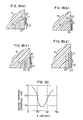
- Fig. 12 shows the reproduction output of heads of different areas of overlapped portions, as plotted against the ratio between the area S 1 of the overlapped portion and the area S 2 of non-overlapped portion. It will be seen that the maximum output is obtained at about 0.3 to 0.4 of S 1 /S 2 .
- the dashed line in the drawing indicates the result of an approximation calculation, which indicates a considerable coincidence. From the viewpoint of system configuration, the output variations of less than -3 dB are desirable, and therefore, a magneto-resistive head of high reproduction efficiency is obtained by constructing the magneto-resistive head in the range 0.1 ⁇ S l /S 2 ⁇ 0.6.
- Fig. 13 shows the reproduction output of the MR head plotted against different ratios between the area S 2 and the area S 3 of the overlapped portion of the MR element 11 and the high permeability thin film 21.
- the maximum output is obtained at or near the value of the ratio S 3 /S 2 equal to 0.3. If the variation less than -3 dB is allowed, the range is 0.1 ⁇ S 3 /S 2 ⁇ 0.5. If this range is satisfied, an MR head with a high output and small variations is obtained.
- the magneto-resistive head described above though suitable for reproduction of the perpendicular magnetization, uses glass of comparatively low melting point suitable as the non-magnetic material to fill in the recessed groove 10 in the general method of fabrication which may be employed for the thin film head.
- a process conceivable for this purpose is to form the protective thin film 24 of Fig. 15 thickly by evaporation of Si0 or the like in close contact with the thin film portion.
- the protective film of SiO projects by about 0.1 to 0.2 ⁇ m from the glass filled portion.
- FIG. 15 Another embodiment improved in this respect is shown in Fig. 15.
- the device shown in the Figure is fabricated in such a way that after the surface of an insulative base plate 8 such as of ferrite is ground, those portion except for the groove which was etched by p hotoetching is covered with a photo-resist so that a groove of a desired depth (about 5 ⁇ m) plus a lapping margin (about 5 um) is formed by use of electrolytic etching technique. After removing the photoresist, the non-magnetic material 10 such as of SiO is formed to the thickness at least more than the depth of the groove.
- the surface of the non-magnetic material 3 of the groove 9 such as SiO is finished by lapping flush with the surface of the ferrite base plate 8 and with the desired depth of the groove.
- Ni-Fe alloy or the 0 like is deposited to the thickness of about 500 A by appropriate evaporation means, and electrodes are arranged at longitudinal ends of the MR element 11 by photoeching process in such a manner that the MR element 11 is provided in parallel to the longitudinal direction of the recessed groove 9.
- the SiO protective film 24 is formed to the thickness of more than 10 ⁇ m by appropriate evaporatoin means.
- the magneto-resistive head fabricated in this way is capable of efficiently reproducing the high- density perpendicular magnetization of submicrons bit length by the operation mentioned above.
- the roughness which otherwise might be caused by such deviated wear near the high-permeability thin films is not cuased due to the fact that the non-magnetic members 10, 24 provided both sides of the high permeability thin film are made of the same material.
- the forward end of the high permeability thin film on the recording medium side is thus kept in constant stable contact with the recording medium, and therefore large shortwavelength- loss does not occur unlike in the prior art, thus producing a reproduction characteristic of very high resolution.
- Fig. 16 shows the wavelength response of this improved magnetic head is compared with that of the conventional magnetic heads.
- the reciprocal of the wavelength X corresponding to the frequency is plotted in abscissa, and the relative output in ordinate.
- the curve a represents the characteristic of the MR element- alone type magneto-resistive head
- the curve b that of the shield-type magneto-resistive head
- the curve c that of the magneto-resistive head earlier proposed in which Vickers hardness of the non-magnetic materials on both sides of the high permeability thin film are considerably different
- the curve d that of the magneto-resistive head according to the above-improved embodiment.
- the recess formed in the surface of an insulative base plate or substrate 8 such as of ferrite is filled with a non-magnetic material 10 such as glass to finish flush with the surface of the substrate 8.
- a conductive material such as Al, Au or Cu is provided to cover the resulting new surface by such means as evaporation thereby to form a biassing conductor layer 25 in parallel to the recess 9 by photoetching.
- An Ni-Fe alloy is deposited on the resulting assembly to the thickness of 0 about 500 A by evaporation means through an insulating layer (not shown).
- Electrodes 12 and 13 are arranged at longitudinal ends of the MR element 11 by photoetching process so that the MR element 11 is arranged along the longitudinal direction of the recessed groove 9.
- An upper end of the MR element 11 is magnetically coupled with the end 15 of the recessed groove 9 in the magnetic substrate, while the lower end of the MR element 11 is magnetically coupled with and electrically insulated from the upper end of the high permeability thin film 21 of substantially the same thickness through an insulating layer (not shown).
- a double-layered perpendicular recording medium including a high-permeability thin film 3 such as of an Ni-Fe alloy and a vertically magnetized medium 2 such as of Co-Cr deposited thereon, which medium is disposed on the base member,4, faces the lower end of the high permeability thin film 21, so that the recording medium is fed along the direction of the arrow 14 thereby to reproduce the verticaly magnetized signals.
- a high-permeability thin film 3 such as of an Ni-Fe alloy
- a vertically magnetized medium 2 such as of Co-Cr deposited thereon
- a sectional view taken in line A-A' at the central part of the MR element 11 is shown in Figs. 18 (a) to (d) to indicate the relative positions of the biassing conductor layer 25 and a conductor 26.
- Fig. 18 (a) shows a sectional view of the biassing conductor layer 25 arranged between the MR element 11 and the magnetic base plate 8 in parallel to the former.
- a current flowing in the conductor layer 25 causes a bias material field to be efficiently applied to the MR element 11 in a closed loop including the MR element 11, high permeability thin film 21, high permeability thin film 3 on the back of the perpendicular magnetized medium and magnetic substrate 8.
- the biassing conductor layer 25 and the MR element 11 are electrically isolated from each other completely by an insulating layer, thus making possible stable impression of the bias magnetic field.
- the bias conductor 25 and the MR element 11 are free of gap loss and electrical leaks, even if the insulating layer (not shown) is made sufficiently large.
- Fig. 18 (c) shows a sectional view of the bias conductor 26 molded in the recess 9 of the base plate by glass or the like.
- the current flowing in the conductor 26 causes a bias magnetic field to be applied to the MR element 11 through the high permeability thin film 21, high permeability thin film 3 in the perpendicular magnetic recording medium and magnetic substrate 8.
- Fig. 18 (d) shows a sectional view of the biassing conductor layer 26 formed in the recessed groove of the substrate, on which a wear-resistant insulating layer 27 of such a material as SiO or Si0 2 is deposited, and further formed thereon are the MR element 11 and the high permeability thin film 21.
- This construction poses no problem of electrical leaks since the conductor layer 26 is completely isolated electrically from the MR element 11.
- a magnetic substrate or base plate use a magnetic substrate or base plate
- the concept of the present invention is not limited to the use of the magnetic substrate or base plate. It is obvious, for example, that a magnetic thin film may be deposited on a non-magnetic substrate and an insulating layer is deposited thereon to an appropriate thickness only at predetermined portion thereby to construct a perpendicular magnetization playback head with an equal effect.
- a recessed groove 9 is formed in the surface of an insulating substrate 8 of such a material as ferrite and is filled with a non-magnetic material 10 such as glass to be finished flush with the surface of the substrate 8.
- a non-magnetic material 10 such as glass to be finished flush with the surface of the substrate 8.
- grating-like portions are formed at predetermined regular intervals with their direction making a certain angle to the direction of electric current flowing through the MR element 11.
- Ni-Fe alloy is further o deposited to the thickness of about 500 A on the assembly by appropriate evaporation means so that electrodes 12 and 13 are arranged at longitudinal ends of the MR element 11, while disposing the MR element 11 in parallel with the recessed groove 9.
- the upper end of the MR element 11 is magnetically coupled with the end of the recessed groove 9 formed in the magnetic substrate, while the lower end of the MR element 11 is electrically isolated from and magnetically coupled with the upper end of the high permeability thin film 21 of substantially the same thickness via an insulating film (not shown).
- the grating-like structure may of course be formed alternatively on the insulating layer.
- the construction of the magnetic head according to the present invention is such that, being a closed loop construction, the demagnetizing factor is reduced, thus making it possible to hold the inclined condition even when the anisotripic magnetic field is comparatively small.
- the operation can be realized with a reduced second high harmonics distortion from the MR element 11 by setting the angle 8 in the range 30° ⁇ 8 ⁇ 60° as shown in Fig. 20.
- reference numeral 28 designates a double-layered perpendicular magnetic recording tape
- numeral 29 a supply reel wound with the tape
- numeral 30 a take-up reel wound with the same tape
- Numeral 31 designates a capstan
- numeral 32 a power source for rotating the capstan.
- Reference character A designates an input signal terminal
- numeral 33 an input signal processing circuit including a recording amplifier
- numeral 34 a recording head
- Numeral 35 designates a magneto- resistive type head
- numeral 36 a reproduction signal processing circuit including a reproduction amplifi.er
- character B an output signal terminal.
- An input signal to be recorded such as an audio signal is applied to the input signal terminal A, converted into a digital signal by an analog-digital converter in the input signal processing circuit 33, encoded by, say, MFM or 3PM, and through a recording head drive circuit, is applied as a signal current to the recording head 34.
- the perpendicular recording tape 28 is fed at a constant speed by the drive source 32 and the capstan 31, and therefore the signal is recorded sequentially in the magnetic tape 28.
- the magneto-resistive playback head 35 is responsive to the signal magnetic field in the tape, and the output thereof is amplified and decoded by the reproduction signal processing circuit 36, followed by digital-analog conversion. The resulting signal is produced as an output signal at terminal B.
- the perpendicular recording head shown in Fig. 1 (a) or the ring recording head shown in Fig.l (b) may be used as desired.
- a head (magneto-resistive head) using a magneto-resistive element is used as a playback head.
- the magneto- resistive head in which the magnitude of the reproduction signal is not dependent on the relative speeds of the head and medium unlike in the head of winding- type shown in Figs. 1 (a) and 1 (b), is advantageously used with a recording and reproducing device of low tape speed.
- the thickness loss and the gap loss mentioned above can be substantially obviated.
- the head described with reference to the second and subsequent embodiments may of course be used as a playback head with the magnetic recording and reproducing device according to the present invention.
Landscapes
- Engineering & Computer Science (AREA)
- Manufacturing & Machinery (AREA)
- Magnetic Heads (AREA)
Applications Claiming Priority (18)
| Application Number | Priority Date | Filing Date | Title |
|---|---|---|---|
| JP62731/82 | 1982-04-14 | ||
| JP57062728A JPS58179927A (ja) | 1982-04-14 | 1982-04-14 | 薄膜磁気ヘツド |
| JP62728/82 | 1982-04-14 | ||
| JP57062731A JPS58179928A (ja) | 1982-04-14 | 1982-04-14 | 薄膜磁気ヘツド |
| JP66699/82 | 1982-04-20 | ||
| JP57066699A JPS58185020A (ja) | 1982-04-20 | 1982-04-20 | 磁気記録再生装置 |
| JP57180730A JPS5971122A (ja) | 1982-10-14 | 1982-10-14 | 薄膜磁気ヘツド |
| JP180724/82 | 1982-10-14 | ||
| JP57180720A JPS5971118A (ja) | 1982-10-14 | 1982-10-14 | 垂直磁化再生ヘツド |
| JP180728/82 | 1982-10-14 | ||
| JP180731/82 | 1982-10-14 | ||
| JP57180731A JPS5971123A (ja) | 1982-10-14 | 1982-10-14 | 薄膜磁気ヘツド |
| JP57180728A JPS5971121A (ja) | 1982-10-14 | 1982-10-14 | 垂直磁化再生ヘツド |
| JP57180721A JPS5971119A (ja) | 1982-10-14 | 1982-10-14 | 磁気抵抗効果形ヘツド |
| JP180720/82 | 1982-10-14 | ||
| JP180721/82 | 1982-10-14 | ||
| JP180730/82 | 1982-10-14 | ||
| JP57180724A JPS5971120A (ja) | 1982-10-14 | 1982-10-14 | 垂直磁化再生方法およびそのための磁気抵抗効果形ヘツド |
Publications (2)
| Publication Number | Publication Date |
|---|---|
| EP0091812A1 true EP0091812A1 (fr) | 1983-10-19 |
| EP0091812B1 EP0091812B1 (fr) | 1987-11-19 |
Family
ID=27577098
Family Applications (1)
| Application Number | Title | Priority Date | Filing Date |
|---|---|---|---|
| EP83302024A Expired EP0091812B1 (fr) | 1982-04-14 | 1983-04-11 | Tête pour la reproduction d'enregistrements magnétiques perpendiculaires |
Country Status (3)
| Country | Link |
|---|---|
| US (1) | US4613918A (fr) |
| EP (1) | EP0091812B1 (fr) |
| DE (1) | DE3374622D1 (fr) |
Cited By (7)
| Publication number | Priority date | Publication date | Assignee | Title |
|---|---|---|---|---|
| EP0122660A1 (fr) * | 1983-04-05 | 1984-10-24 | Koninklijke Philips Electronics N.V. | Tête magnétique à bande mince de matériau magnétorésistif utilisée comme élément de lecture |
| DE3438472A1 (de) * | 1983-10-20 | 1985-05-15 | Matsushita Electric Industrial Co., Ltd., Kadoma, Osaka | Duennfilmmagnetkopf |
| DE3500159A1 (de) * | 1984-01-05 | 1985-07-18 | Matsushita Electric Industrial Co., Ltd., Kadoma, Osaka | Duennfilm-magnetkopf |
| DE3607501A1 (de) * | 1985-03-07 | 1986-09-11 | Victor Company Of Japan, Ltd., Yokohama, Kanagawa | Quermagnetisierungsaufzeichnungs- und wiedergabeanordnung |
| US4803581A (en) * | 1983-09-26 | 1989-02-07 | Sharp Kabushiki Kaisha | Thin film yoke-type magnetoresistive head |
| EP0600549A3 (en) * | 1992-12-01 | 1996-06-26 | Koninkl Philips Electronics Nv | Thin-film magnetic head and method of manufacturing the magnetic head. |
| US6150918A (en) * | 1995-05-03 | 2000-11-21 | Bc Components Holdings B.V. | Degaussing unit comprising one or two thermistors |
Families Citing this family (37)
| Publication number | Priority date | Publication date | Assignee | Title |
|---|---|---|---|---|
| JPS61178713A (ja) * | 1985-02-05 | 1986-08-11 | Victor Co Of Japan Ltd | 薄膜磁気センサ |
| US4754354A (en) * | 1986-05-05 | 1988-06-28 | Eastman Kodak Company | Ferrite film insulating layer in a yoke-type magneto-resistive head |
| US5159511A (en) * | 1987-04-01 | 1992-10-27 | Digital Equipment Corporation | Biasing conductor for MR head |
| US4843505A (en) * | 1988-04-25 | 1989-06-27 | Magnetic Peripherals Inc. | Magnetoresistive sensing element with a projection for enhanced data reading |
| US5085935A (en) * | 1988-08-03 | 1992-02-04 | Digital Equipment Corporation | Flux spreading thin film magnetic devices |
| CA1334447C (fr) * | 1988-08-03 | 1995-02-14 | Digital Equipment Corporation | Anisotropie perpendiculaire dans les dispositifs en couches minces |
| US5089334A (en) * | 1988-08-03 | 1992-02-18 | Digital Equipment Corporation | Flux spreading thin film magnetic devices |
| US5428893A (en) * | 1989-06-02 | 1995-07-04 | Quantum Corporation | Method of making a transducer with improved inductive coupling |
| US5311386A (en) * | 1989-06-02 | 1994-05-10 | Digital Equipment Corporation | Transducer with improved inductive coupling |
| US5184267A (en) * | 1989-06-02 | 1993-02-02 | Digital Equipment Corporation | Transducer with improved inductive coupling |
| US5195005A (en) * | 1989-06-02 | 1993-03-16 | Digital Equipment Corporation | Tranducer with improved inductive coupling |
| US6320725B1 (en) * | 1989-11-27 | 2001-11-20 | Censtor Corporation | Hard disk drive having ring head with predominantly perpendicular media fields |
| JPH04290979A (ja) * | 1991-03-20 | 1992-10-15 | Hitachi Ltd | 磁気センサ、磁気センサを持つ位置検出装置および磁気センサを利用したトルク検出装置、モータ制御装置、あるいはこのトルク検出装置を有する電動パワーステアリング装置 |
| JP3106541B2 (ja) * | 1991-04-15 | 2000-11-06 | 日本電気株式会社 | 磁気ヘッド駆動回路 |
| US5269895A (en) * | 1991-05-21 | 1993-12-14 | North American Philips Corporation | Method of making composite structure with single domain magnetic element |
| US5331496A (en) * | 1992-02-14 | 1994-07-19 | Digital Equipment Corporation | Thin-film magnetic transducer with a multitude of magnetic flux interactions |
| US5384434A (en) * | 1992-03-02 | 1995-01-24 | Murata Manufacturing Co., Ltd. | Multilayer ceramic circuit board |
| US6004654A (en) * | 1995-02-01 | 1999-12-21 | Tdk Corporation | Magnetic multilayer film, magnetoresistance element, and method for preparing magnetoresistance element |
| JP3514863B2 (ja) * | 1995-02-01 | 2004-03-31 | 輝也 新庄 | 磁気抵抗効果多層膜、磁気抵抗効果素子および磁気抵抗効果素子の製造方法 |
| US5867350A (en) * | 1995-03-29 | 1999-02-02 | Sony Corporation | Magneto-resistance effect head with insulated bias conductor embedded in shield groove |
| FR2786909B1 (fr) * | 1998-12-03 | 2001-01-05 | Jean Pierre Lazarri | Tete magnetique de lecture a magnetoresistance geante pour hautes densites d'informations |
| US6876519B1 (en) | 1999-09-20 | 2005-04-05 | Seagate Technology Llc | Magnetic recording head including background magnetic field generator |
| US6898053B1 (en) | 1999-10-26 | 2005-05-24 | Seagate Technology Llc | Perpendicular recording head with trackwidth defined by plating thickness |
| US6531202B1 (en) | 1999-11-29 | 2003-03-11 | Seagate Technology Llc | Perpendicular magnetic recording media with reduced-noise soft magnetic underlayer |
| US6560069B1 (en) | 1999-11-29 | 2003-05-06 | Seagate Technology, Llc | Perpendicular recording head defining the trackwidth by material deposition thickness |
| US6816339B1 (en) | 2000-01-10 | 2004-11-09 | Seagate Technology Llc | Perpendicular magnetic recording head with longitudinal magnetic field generator to facilitate magnetization switching |
| US6667848B1 (en) | 2000-01-10 | 2003-12-23 | Seagate Technology Llc | Perpendicular magnetic recording head with means for suppressing noise from soft magnetic underlayer of recording media |
| US6646827B1 (en) | 2000-01-10 | 2003-11-11 | Seagate Technology Llc | Perpendicular magnetic recording head with write pole which reduces flux antenna effect |
| US6574072B1 (en) | 2000-01-12 | 2003-06-03 | Seagate Technology Llc | Perpendicular magnetic recording head with radial magnetic field generator which reduces noise from soft magnetic underlayer of recording disk |
| US6660357B1 (en) | 2000-02-04 | 2003-12-09 | Seagate Technology Llc | Perpendicular magnetic recording media with laminated soft magnetic underlayer |
| US6693768B1 (en) * | 2000-03-15 | 2004-02-17 | Seagate Technology Llc | Perpendicular magnetic recording head having a flux focusing main pole |
| US6717770B1 (en) | 2000-03-24 | 2004-04-06 | Seagate Technology Llc | Recording head for applying a magnetic field perpendicular to the magnetizations within magnetic storage media |
| US6798615B1 (en) | 2000-03-24 | 2004-09-28 | Seagate Technology Llc | Perpendicular recording head with return poles which reduce flux antenna effect |
| US7139156B1 (en) * | 2002-06-20 | 2006-11-21 | Storage Technology Corporation | Non-penetration of periodic structure to PM |
| US7545602B1 (en) * | 2005-07-26 | 2009-06-09 | Sun Microsystems, Inc. | Use of grating structures to control asymmetry in a magnetic sensor |
| US8963544B2 (en) * | 2008-09-29 | 2015-02-24 | The Research Institute For Electric And Magnetic Materials | Signal transmission device |
| US9134386B2 (en) * | 2011-06-28 | 2015-09-15 | Oracle International Corporation | Giant magnetoresistive sensor having horizontal stabilizer |
Citations (4)
| Publication number | Priority date | Publication date | Assignee | Title |
|---|---|---|---|---|
| DE2650484A1 (de) * | 1975-11-18 | 1977-06-08 | Ibm | Magnetoresistiver duennfilm-abtastkopf |
| AT351795B (de) * | 1975-12-29 | 1979-08-10 | Sony Corp | Magnetfeld-messfuehler zur erzeugung eines aus- gangssignals |
| DE2442566B2 (de) * | 1973-10-04 | 1981-04-16 | International Business Machines Corp., 10504 Armonk, N.Y. | Magnetoresistiver Signalwandler |
| GB2091025A (en) * | 1980-12-26 | 1982-07-21 | Sony Corp | Magnetic transducer heads utilizing magneto-resistance effect |
Family Cites Families (14)
| Publication number | Priority date | Publication date | Assignee | Title |
|---|---|---|---|---|
| NL130450C (fr) * | 1958-11-18 | |||
| US4300177A (en) * | 1975-07-17 | 1981-11-10 | U.S. Philips Corporation | Thin-film magnetic head for reading and writing information |
| JPS52119213A (en) * | 1976-03-30 | 1977-10-06 | Matsushita Electric Ind Co Ltd | Magnetic head and its production |
| JPS54119220A (en) * | 1978-03-08 | 1979-09-17 | Olympus Optical Co Ltd | Magnetic head |
| JPS6031006B2 (ja) * | 1978-04-03 | 1985-07-19 | オリンパス光学工業株式会社 | 磁気ヘツド |
| NL7901578A (nl) * | 1979-02-28 | 1980-09-01 | Philips Nv | Magnetoweerstandkop. |
| US4255772A (en) * | 1979-06-29 | 1981-03-10 | International Business Machines Corporation | Read/write magnetic head assembly with magnetoresistive sensor |
| US4383284A (en) * | 1979-12-14 | 1983-05-10 | Tokyo Shibaura Denki Kabushiki Kaisha | Perpendicular magnetic head and method of manufacturing the same |
| US4317148A (en) * | 1980-01-24 | 1982-02-23 | Sperry Corporation | Transducer for perpendicular magnetic recording |
| JPS56165918A (en) * | 1980-05-23 | 1981-12-19 | Ricoh Co Ltd | Vertical magnetic recorder and reproducer |
| JPS57100606A (en) * | 1980-12-15 | 1982-06-22 | Sharp Corp | Vertical magnetic recording and reproducing system |
| JPS6053369B2 (ja) * | 1980-12-29 | 1985-11-25 | 富士通株式会社 | 薄膜磁気ヘッド及びその製造方法 |
| US4423450A (en) * | 1981-05-06 | 1983-12-27 | Censtor Corporation | Magnetic head and multitrack transducer for perpendicular recording and method for fabricating |
| DE3229774C2 (de) * | 1981-08-10 | 1987-05-07 | Matsushita Electric Industrial Co., Ltd., Kadoma, Osaka | Magnetoresistives Bauelement |
-
1983
- 1983-04-11 DE DE8383302024T patent/DE3374622D1/de not_active Expired
- 1983-04-11 US US06/483,614 patent/US4613918A/en not_active Expired - Lifetime
- 1983-04-11 EP EP83302024A patent/EP0091812B1/fr not_active Expired
Patent Citations (4)
| Publication number | Priority date | Publication date | Assignee | Title |
|---|---|---|---|---|
| DE2442566B2 (de) * | 1973-10-04 | 1981-04-16 | International Business Machines Corp., 10504 Armonk, N.Y. | Magnetoresistiver Signalwandler |
| DE2650484A1 (de) * | 1975-11-18 | 1977-06-08 | Ibm | Magnetoresistiver duennfilm-abtastkopf |
| AT351795B (de) * | 1975-12-29 | 1979-08-10 | Sony Corp | Magnetfeld-messfuehler zur erzeugung eines aus- gangssignals |
| GB2091025A (en) * | 1980-12-26 | 1982-07-21 | Sony Corp | Magnetic transducer heads utilizing magneto-resistance effect |
Cited By (9)
| Publication number | Priority date | Publication date | Assignee | Title |
|---|---|---|---|---|
| EP0122660A1 (fr) * | 1983-04-05 | 1984-10-24 | Koninklijke Philips Electronics N.V. | Tête magnétique à bande mince de matériau magnétorésistif utilisée comme élément de lecture |
| US4803581A (en) * | 1983-09-26 | 1989-02-07 | Sharp Kabushiki Kaisha | Thin film yoke-type magnetoresistive head |
| DE3438472A1 (de) * | 1983-10-20 | 1985-05-15 | Matsushita Electric Industrial Co., Ltd., Kadoma, Osaka | Duennfilmmagnetkopf |
| US4700252A (en) * | 1983-10-20 | 1987-10-13 | Matsushita Electric Industrial Co., Ltd. | Magnetic thin film head |
| DE3500159A1 (de) * | 1984-01-05 | 1985-07-18 | Matsushita Electric Industrial Co., Ltd., Kadoma, Osaka | Duennfilm-magnetkopf |
| DE3607501A1 (de) * | 1985-03-07 | 1986-09-11 | Victor Company Of Japan, Ltd., Yokohama, Kanagawa | Quermagnetisierungsaufzeichnungs- und wiedergabeanordnung |
| US4745510A (en) * | 1985-03-07 | 1988-05-17 | Victor Company Of Japan, Ltd. | Perpendicular magnetic recording and reproducing system |
| EP0600549A3 (en) * | 1992-12-01 | 1996-06-26 | Koninkl Philips Electronics Nv | Thin-film magnetic head and method of manufacturing the magnetic head. |
| US6150918A (en) * | 1995-05-03 | 2000-11-21 | Bc Components Holdings B.V. | Degaussing unit comprising one or two thermistors |
Also Published As
| Publication number | Publication date |
|---|---|
| EP0091812B1 (fr) | 1987-11-19 |
| US4613918A (en) | 1986-09-23 |
| DE3374622D1 (en) | 1987-12-23 |
Similar Documents
| Publication | Publication Date | Title |
|---|---|---|
| US4613918A (en) | Perpendicular magnetic playback head and a perpendicular magnetic recording and reproducing device | |
| US4413297A (en) | Magnetic recording and playback apparatus of perpendicular recording type | |
| GB1453288A (en) | Record-replay magnetic transducers | |
| Hokkyo et al. | A new W-shaped single-pole head and a high density flexible disk perpendicular magnetic recording system | |
| US4700252A (en) | Magnetic thin film head | |
| US4907115A (en) | Super conducting thin-film magnetic head including a magnetoresistive element | |
| CA1179771A (fr) | Tete d'enregistrement magnetique perpendiculaire | |
| US5905610A (en) | Combined read/write magnetic head having MRE positioned between broken flux guide and non-magnetic substrate | |
| JPS62145527A (ja) | 複合型薄膜磁気ヘツド | |
| US4821012A (en) | Magnetoresistive element | |
| JP2814741B2 (ja) | 垂直磁化型磁気抵抗素子とそれを用いた磁気抵抗効果型磁気ヘッド | |
| US4654739A (en) | Thin film magnetic head for reproducing perpendicular magnetization | |
| EP0029550A1 (fr) | Tête magnétique multivoie, appareil utilisant une telle tête, et procédé de fabrication d'une telle tête | |
| JPS6224848B2 (fr) | ||
| JP2786783B2 (ja) | 複合型磁気ヘッド | |
| JP2878738B2 (ja) | 記録再生兼用薄膜磁気ヘッド | |
| Raemaekers | Recording experiments with multi-track thin-film heads | |
| JPS6286521A (ja) | 薄膜磁気ヘツド | |
| JPH0234082B2 (fr) | ||
| JPH06325331A (ja) | 磁気抵抗効果ヘッド | |
| JPS6132215A (ja) | 磁気抵抗効果型ヘツド | |
| JPS58102321A (ja) | 磁気ヘツド | |
| JPH0440773B2 (fr) | ||
| JPH02762B2 (fr) | ||
| JPS58179928A (ja) | 薄膜磁気ヘツド |
Legal Events
| Date | Code | Title | Description |
|---|---|---|---|
| PUAI | Public reference made under article 153(3) epc to a published international application that has entered the european phase |
Free format text: ORIGINAL CODE: 0009012 |
|
| AK | Designated contracting states |
Designated state(s): DE FR GB |
|
| 17P | Request for examination filed |
Effective date: 19840315 |
|
| GRAA | (expected) grant |
Free format text: ORIGINAL CODE: 0009210 |
|
| AK | Designated contracting states |
Kind code of ref document: B1 Designated state(s): DE FR GB |
|
| REF | Corresponds to: |
Ref document number: 3374622 Country of ref document: DE Date of ref document: 19871223 |
|
| ET | Fr: translation filed | ||
| PLBE | No opposition filed within time limit |
Free format text: ORIGINAL CODE: 0009261 |
|
| STAA | Information on the status of an ep patent application or granted ep patent |
Free format text: STATUS: NO OPPOSITION FILED WITHIN TIME LIMIT |
|
| 26N | No opposition filed | ||
| PGFP | Annual fee paid to national office [announced via postgrant information from national office to epo] |
Ref country code: FR Payment date: 19990409 Year of fee payment: 17 |
|
| PGFP | Annual fee paid to national office [announced via postgrant information from national office to epo] |
Ref country code: GB Payment date: 19990415 Year of fee payment: 17 |
|
| PGFP | Annual fee paid to national office [announced via postgrant information from national office to epo] |
Ref country code: DE Payment date: 19990419 Year of fee payment: 17 |
|
| PG25 | Lapsed in a contracting state [announced via postgrant information from national office to epo] |
Ref country code: GB Free format text: LAPSE BECAUSE OF NON-PAYMENT OF DUE FEES Effective date: 20000411 |
|
| PG25 | Lapsed in a contracting state [announced via postgrant information from national office to epo] |
Ref country code: DE Free format text: LAPSE BECAUSE OF NON-PAYMENT OF DUE FEES Effective date: 20000430 |
|
| GBPC | Gb: european patent ceased through non-payment of renewal fee |
Effective date: 20000411 |
|
| PG25 | Lapsed in a contracting state [announced via postgrant information from national office to epo] |
Ref country code: FR Free format text: LAPSE BECAUSE OF NON-PAYMENT OF DUE FEES Effective date: 20001229 |
|
| REG | Reference to a national code |
Ref country code: FR Ref legal event code: ST |