EP0091848A1 - Manche de commande débrayable pour copilote d'aéronef - Google Patents
Manche de commande débrayable pour copilote d'aéronef Download PDFInfo
- Publication number
- EP0091848A1 EP0091848A1 EP83400580A EP83400580A EP0091848A1 EP 0091848 A1 EP0091848 A1 EP 0091848A1 EP 83400580 A EP83400580 A EP 83400580A EP 83400580 A EP83400580 A EP 83400580A EP 0091848 A1 EP0091848 A1 EP 0091848A1
- Authority
- EP
- European Patent Office
- Prior art keywords
- handle
- pilot
- ring
- bolt
- aircraft
- Prior art date
- Legal status (The legal status is an assumption and is not a legal conclusion. Google has not performed a legal analysis and makes no representation as to the accuracy of the status listed.)
- Granted
Links
- 230000008878 coupling Effects 0.000 claims description 5
- 238000010168 coupling process Methods 0.000 claims description 5
- 238000005859 coupling reaction Methods 0.000 claims description 5
- 230000006835 compression Effects 0.000 claims description 3
- 238000007906 compression Methods 0.000 claims description 3
- 238000004873 anchoring Methods 0.000 claims description 2
- 238000002955 isolation Methods 0.000 abstract 1
- 230000000694 effects Effects 0.000 description 3
- 230000021615 conjugation Effects 0.000 description 2
- 230000009977 dual effect Effects 0.000 description 1
- 210000000056 organ Anatomy 0.000 description 1
- 230000002040 relaxant effect Effects 0.000 description 1
Images

Classifications
-
- B—PERFORMING OPERATIONS; TRANSPORTING
- B64—AIRCRAFT; AVIATION; COSMONAUTICS
- B64C—AEROPLANES; HELICOPTERS
- B64C13/00—Control systems or transmitting systems for actuating flying-control surfaces, lift-increasing flaps, air brakes, or spoilers
- B64C13/02—Initiating means
- B64C13/04—Initiating means actuated personally
- B64C13/12—Dual control apparatus
-
- B—PERFORMING OPERATIONS; TRANSPORTING
- B64—AIRCRAFT; AVIATION; COSMONAUTICS
- B64C—AEROPLANES; HELICOPTERS
- B64C13/00—Control systems or transmitting systems for actuating flying-control surfaces, lift-increasing flaps, air brakes, or spoilers
- B64C13/02—Initiating means
- B64C13/04—Initiating means actuated personally
- B64C13/042—Initiating means actuated personally operated by hand
- B64C13/0421—Initiating means actuated personally operated by hand control sticks for primary flight controls
-
- G—PHYSICS
- G05—CONTROLLING; REGULATING
- G05G—CONTROL DEVICES OR SYSTEMS INSOFAR AS CHARACTERISED BY MECHANICAL FEATURES ONLY
- G05G11/00—Manually-actuated control mechanisms provided with two or more controlling members co-operating with one single controlled member
-
- G—PHYSICS
- G05—CONTROLLING; REGULATING
- G05G—CONTROL DEVICES OR SYSTEMS INSOFAR AS CHARACTERISED BY MECHANICAL FEATURES ONLY
- G05G9/00—Manually-actuated control mechanisms provided with one single controlling member co-operating with two or more controlled members, e.g. selectively, simultaneously
- G05G9/02—Manually-actuated control mechanisms provided with one single controlling member co-operating with two or more controlled members, e.g. selectively, simultaneously the controlling member being movable in different independent ways, movement in each individual way actuating one controlled member only
- G05G9/04—Manually-actuated control mechanisms provided with one single controlling member co-operating with two or more controlled members, e.g. selectively, simultaneously the controlling member being movable in different independent ways, movement in each individual way actuating one controlled member only in which movement in two or more ways can occur simultaneously
- G05G9/047—Manually-actuated control mechanisms provided with one single controlling member co-operating with two or more controlled members, e.g. selectively, simultaneously the controlling member being movable in different independent ways, movement in each individual way actuating one controlled member only in which movement in two or more ways can occur simultaneously the controlling member being movable by hand about orthogonal axes, e.g. joysticks
-
- G—PHYSICS
- G05—CONTROLLING; REGULATING
- G05G—CONTROL DEVICES OR SYSTEMS INSOFAR AS CHARACTERISED BY MECHANICAL FEATURES ONLY
- G05G9/00—Manually-actuated control mechanisms provided with one single controlling member co-operating with two or more controlled members, e.g. selectively, simultaneously
- G05G9/02—Manually-actuated control mechanisms provided with one single controlling member co-operating with two or more controlled members, e.g. selectively, simultaneously the controlling member being movable in different independent ways, movement in each individual way actuating one controlled member only
- G05G9/04—Manually-actuated control mechanisms provided with one single controlling member co-operating with two or more controlled members, e.g. selectively, simultaneously the controlling member being movable in different independent ways, movement in each individual way actuating one controlled member only in which movement in two or more ways can occur simultaneously
- G05G9/047—Manually-actuated control mechanisms provided with one single controlling member co-operating with two or more controlled members, e.g. selectively, simultaneously the controlling member being movable in different independent ways, movement in each individual way actuating one controlled member only in which movement in two or more ways can occur simultaneously the controlling member being movable by hand about orthogonal axes, e.g. joysticks
- G05G2009/04703—Mounting of controlling member
- G05G2009/04714—Mounting of controlling member with orthogonal axes
- G05G2009/04718—Mounting of controlling member with orthogonal axes with cardan or gimbal type joint
-
- Y—GENERAL TAGGING OF NEW TECHNOLOGICAL DEVELOPMENTS; GENERAL TAGGING OF CROSS-SECTIONAL TECHNOLOGIES SPANNING OVER SEVERAL SECTIONS OF THE IPC; TECHNICAL SUBJECTS COVERED BY FORMER USPC CROSS-REFERENCE ART COLLECTIONS [XRACs] AND DIGESTS
- Y10—TECHNICAL SUBJECTS COVERED BY FORMER USPC
- Y10T—TECHNICAL SUBJECTS COVERED BY FORMER US CLASSIFICATION
- Y10T74/00—Machine element or mechanism
- Y10T74/20—Control lever and linkage systems
- Y10T74/20207—Multiple controlling elements for single controlled element
- Y10T74/20213—Interconnected
-
- Y—GENERAL TAGGING OF NEW TECHNOLOGICAL DEVELOPMENTS; GENERAL TAGGING OF CROSS-SECTIONAL TECHNOLOGIES SPANNING OVER SEVERAL SECTIONS OF THE IPC; TECHNICAL SUBJECTS COVERED BY FORMER USPC CROSS-REFERENCE ART COLLECTIONS [XRACs] AND DIGESTS
- Y10—TECHNICAL SUBJECTS COVERED BY FORMER USPC
- Y10T—TECHNICAL SUBJECTS COVERED BY FORMER US CLASSIFICATION
- Y10T74/00—Machine element or mechanism
- Y10T74/20—Control lever and linkage systems
- Y10T74/20576—Elements
- Y10T74/20636—Detents
Definitions
- the invention relates to a control stick for an aircraft co-pilot (such as a helicopter) connected to the pilot stick by a coupling linkage which forces the two sticks to remain parallel when they move angularly around a pivot center specific to each of them and which comprises two articulated parallel rods forming with the longitudinal axes of the sleeves a deformable parallelogram, one of these rods, the points of articulation of which coincide with the pivot centers of the sleeves, being a torsionally rigid shaft which can rotate in bearings, the other rod being a connecting rod working in traction or in compression.
- the present invention relates to a co-pilot handle provided with a mechanical clutch and instantaneous clutch device which prevents its inadvertent movement while leaving the possibility of the co-pilot intervening at any time according to the needs of the mission.
- a double gimbal comprising an outer ring and an inner ring whose two axes of articulation intersect at the pivot center of said handle, its outer ring on the one hand being articulated to the aforementioned shaft and on the other hand being integral with a part articulated with the aforementioned connecting rod, while said sleeve is connected to said part by an erasable locking device which allows to attach and detach at will the handle and the outer ring of the double gimbal.
- the co-pilot handle is coupled to the pilot handle and allows normal control of the aircraft.
- the double gimbal completely isolates this handle from the pilot handle, which is thus put out of service, the wheelhouse then being able to operate only under the sole solicitation of the pilot handle.
- the locking device for the copilot's handle comprises a bolt emerging coaxially from the handle at its end and engaging, for locking, in a keeper provided by the bottom of a shaped part bowl belonging to said piece secured to the outer ring, while the handle can slide longitudinally in the double gimbal, unlocking is obtained by pulling on the handle so as to remove the bolt from the strike.
- the co-pilot's handle in the unlocked situation, can be immobilized by means of a device for hooking at a fixed point of the structure of the aircraft.
- a device for hooking may include a hook secured to the handle and a fixed anchoring member with which it is possible to engage the hook.
- the handle according to the invention is provided with a return spring which communicates to it an elastic holding force either in the locked position or in the hooked position after unlocking.
- the bowl belonging to said piece integral with the external ring internally offers a frustoconical shape and that the handle has at its end a tip of conjugate shape which fits exactly into the bottom of this bowl.
- the locking bolt should be movable and can be erased in the handle by pressing against the force of a return spring tending to cause it to emerge from the end of the handle.
- FIG. 1 shows an arrangement for cyclically controlling the rotor of a helicopter, comprising a handle 1 intended for the pilot of the aircraft and a handle 2 intended for the co-pilot.
- a handle 1 intended for the pilot of the aircraft
- a handle 2 intended for the co-pilot.
- This wheelhouse comprises a shaft 6 for conjugation in pitch and a connecting rod 7 for conjugation in roll which form with the axes 8, 9 of the handles 1, 2 a deformable parallelogram.
- the ring 14 is connected to the handle 2 by a cardan ring 17 which is articulated to the ring 14 along an axis BB and to a ring 18 surrounding the handle 2 along an axis CC perpendicular to the axis BB.
- the rings 24, 14, 17 and 18 are concentric and the axes AA, BB and CC all pass through the pivot center 4 of the handle 2.
- the handle 2 is not hinged directly to the shaft 6, but by means of a double gimbal whose external ring is the ring 17 and the internal ring the ring 14, the axes CC and AA being separate.
- these two axes are required to be merged by securing the handle 2 and its ring 18 with the part 13 and its ring 14.
- This situation is obtained thanks to a locking device constituted by a bolt 19 sliding coaxially inside the handle 2 and which can emerge from the end of the latter, under the action of a compression spring 20, to engage in a keeper formed by a hole 21 drilled in the center of the bottom of the bowl 16 of the part 13.
- the handle 2 is slidably mounted in the ring 18, its end, provided with a nozzle 22 whose shape matches that of the bottom of the bowl 16, being applied against the latter by a return spring 23 interposed between the ring 18 and said end piece 22.
- a hooking device comprising a hook 26 fixed to said handle at a certain height from its barrel and a member anchor 27 fixed.
- the co-pilot tilts the handle 2 forwards in order to engage his hook 26 with the member 27.
Landscapes
- Engineering & Computer Science (AREA)
- Automation & Control Theory (AREA)
- Physics & Mathematics (AREA)
- General Physics & Mathematics (AREA)
- Aviation & Aerospace Engineering (AREA)
- Mechanical Control Devices (AREA)
- Mutual Connection Of Rods And Tubes (AREA)
Abstract
Description
- L'invention se rapporte à un manche de commande pour copilote d'aéronef (tel qu'un hélicoptère) relié au manche de pilote par une timonerie d'accouplement qui oblige les deux manches à rester parallèleslorsqu'ils se déplacent angulairement autour d'un centre de pivotement propre à chacun d'eux et qui comprend deux tiges parallèles articulées formant avec les axes longitudinaux des manches un parallélogramme déformable, l'une de ces tiges, dont les points d'articulation sont confondus avec les centres de pivotement des manches, étant un arbre rigide en torsion pouvant tourner dans des paliers, l'autre tige étant une bielle travaillant à la traction ou à la compression.
- Sur les aéronefs à double commande comportant un manche de pilote et un manche de copilote, il peut être gênant, et même dans certains cas dangereux, que, lorsque le copilote n'assure pas la conduite de l'appareil et qu'il est occupé à d'autres tâches, par exemple à la recherche d'objectifs ou à la navigation, le manche de commande placé devant lui ne puisse être totalement débrayé de la timonerie principale, de façon à éviter des à-coups dans la conduite de l'appareil, si cette commande, en général très sensible, est déplacée involontairement par le copilote.
- La présente invention concerne un manche de copilote doté d'un dispositif mécanique de débrayage et d'embrayage instantané qui évite son déplacement intempestif tout en laissant la possibilité au copilote d'intervenir à tout instant suivant les besoins de la mission.
- A cet effet, selon l'invention, entre les tiges de la timonerie d'accouplement précitée et le manche de copilote est interposé un double cardan comprenant un anneau externe et un anneau interne dont les deux axes d'articulation se croisent au centre de pivotement dudit manche, son anneau externe d'une part étant articulé à l'arbre précité et d'autre part étant solidaire d'une pièce articulée à la bielle précitée, tandis que ledit manche est relié à ladite pièce par un dispositif de verrouillage effaçable qui permet de solidariser et de désolidariser à volonté le manche et l'anneau externe du double cardan. Lorsqu'il y a solidarisation, le manche de copilote est couplé au manche de pilote et permet de commander normalement l'appareil. Lorsqu'on désolidarise le manche de copilote dudit anneau externe, le double cardan isole complètement du manche de pilote ce manche, qui est ainsi mis hors service, la timonerie ne pouvant alors fonctionner que sous la seule sollicitation du manche de pilote.
- Dans une forme d'exécution avantageuse, le dispositif de verrouillage du manche de copilote comprend un pêne émergeant coaxialement du manche à son extrémité et s'engageant, pour assurer le verrouillage, dans une gâche qu'offre le fond d'une partie en forme de cuvette appartenant à ladite pièce solidaire de l'anneau externe, tandis que le manche peut coulisser longitudinalement dans le double cardan, le déverrouillage s'obtenant par traction sur le manche de manière à faire sortir le pêne de la gâche.
- Il est préférable de prévoir que le manche de copilote, en situation de déverrouillage, puisse être immobilisé au moyen d'un dispositif d'accrochage à un point fixe de la structure de l'appareil. Un tel dispositif d'accrochage peut comprendre un crochet solidaire du manche et un organe d'ancrage fixe avec lequel il est possible d'amener en prise le crochet. De préférence, le manche selon l'invention est doté d'un ressort de rappel qui lui communique une force élastique de maintien soit en situation de verrouillage, soit en position d'accrochage après déverrouillage. En outre, il est avantageux que la cuvette appartenant à ladite pièce solidaire de l'anneau externe offre intérieurement une forme tronconique et que le manche comporte à son extrémité un embout de forme conjuguée qui s'emboîte exactement dans le fond de cette cuvette. Par ailleurs, il convient que le pêne de verrouillage soit mobile et puisse s'effacer dans le manche par enfoncement à l'encontre de la force d'un ressort de rappel tendant à le faire émerger de l'extrémité du manche.
- La description qui va suivre, en regard des dessins annexés à titre d'exemple non limitatif, permettra de bien comprendre comment la présente invention peut être mise en pratique.
- La figure 1 représente en élévation un agencement de double commande pour aéronef, le manche de copilote étant montré en coupe longitudinale.
- La figure 2 représente une coupe selon la ligne II-II de l'objet de la figure 1.
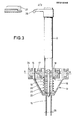
- La figure 3 représente une coupe suivant la ligne III-III de l'objet de la figure 1 montrant le manche de copilote verrouillé en situation d'activité.
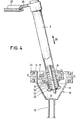
- La figure 4 représente, à la manière de la figure 3, le manche de copilote déverrouillé et immobilisé en situation hors service.
- On voit sur la figure 1 un agencement de commande cyclique du rotor d'un hélicoptère, comprenant un manche 1 destiné au pilote de l'appareil et un manche 2 destiné au copilote. Lors de leur utilisation où ils sont déplacés angulairement, par manoeuvre de leurs poignées 11 respectives, en roulis ou en tangage autour de centres de pivotement 3,4 respectifs, ces manches 1,2 sont astreints à rester en parallélisme grâce à une timonerie d'accouplement 5. Cette timonerie comprend un arbre 6 de conjugaison en tangage et une bielle 7 de conjugaison en roulis qui forment avec les axes 8,9 des manches 1,2 un parallélogramme déformable.
- L'arbre 6, qui est rigide en torsion et peut tourner dans des paliers 10 fixes, est articulé au manche 1 suivant un axe passant par le centre de pivotement 3 de celui-ci, et la bielle 7 est articulée en 12 à l'extrémité inférieure dudit manche.
- A leur autre extrémité, par contre, il y a articulation de l'arbre 6 et de la bielle 7 non pas directement au manche de copilote 2, mais à une pièce intermédiaire 13 comprenant à sa partie supérieure un anneau de cardan 14 auquel est articulé suivant un axe AA (figure 2) l'arbre 6 par un anneau 24 solidaire de ce dernier, et à sa partie inférieure une fourche 15 à laquelle est articulée en 28 la bielle 7, l'anneau 14 et la fourche 15 étant réunis par une partie 16 en forme de cuvette tronconique.
- L'anneau 14 est relié au manche 2 par un anneau de cardan 17 qui est articulé à l'anneau 14 suivant un axe BB et à un anneau 18 ceinturant le manche 2 suivant un axe CC perpendiculaire à l'axe BB. Les anneaux 24, 14, 17 et 18 sont concentriques et les axes AA, BB et CC passent tous par le centre de pivotement 4 du manche 2.
- Ainsi, le manche 2 n'est pas articulé directement à l'arbre 6, mais par l'intermédiaire d'un double cardan dont l'anneau externe est l'anneau 17 et l'anneau interne l'anneau 14, les axes CC et AA étant distincts. Toutefois, en fonctionnement normal, ces deux axes sont astreints à être confondus par solidarisation du manche 2 et de son anneau 18 avec la pièce 13 et son anneau 14. Cette situation est obtenue grâce à un dispositif de verrouillage constitué par un pêne 19 coulissant coaxialement à l'intérieur du manche 2 et pouvant émerger de l'extrémité de celui-ci, sous l'action d'un ressort de compression 20, pour s'engager dans une gâche formée par un trou 21 percé au centre du fond de la cuvette 16 de la pièce 13. Par ailleurs, le manche 2 est monté coulissant dans l'anneau 18, son extrémité, munie d'un embout 22 dont la forme épouse celle du fond de la cuvette 16, étant appliquée contre celui-ci par un ressort de rappel 23 interposé entre l'anneau 18 et ledit embout 22.
- Lorsque le manche 2 et la pièce 13 sont en situation de verrouillage mutuel (figures 1 et 3), les axes AA et CC sont nécessairement confondus, les articulations de l'anneau 17 étant inopérantes. Le manche 2 se trouve alors articulé à l'arbre 6 et à la bielle 7 comme l'est le manche 1. Les deux manches sont couplés et chacun d'eux peut être utilisé indifféremment pour commander l'hélicoptère.
- Lorsque le copilote ne désire pas se servir de son manche 2, il tire celui-ci vers le haut suivant la flèche 25 (figure 4), ce qui a pour effet, par coulissement du manche 2 dans l'anneau 18, de faire sortir le pêne 19 de la gâche 21, l'embout 22 quittant le fond de la cuvette 16. Le manche 2 se trouve ainsi débrayé, c'est-à-dire désaccouplé du manche 1, qui seul permet alors la commande de l'hélicoptère, tandis que l'arbre 6 et la bielle 7 peuvent débattre librement en entraînant la pièce 13, mais non le manche 2 qui en est isolé par le double cardan 14, 17.
- Il convient ensuite d'immobiliser le manche 2 en situation de déverrouillage, ce qui est réalisé dans le présent exemple à l'aide d'un dispositif d'accrochage comprenant un crochet 26 fixé audit manche à une certaine hauteur de son fût et un organe d'ancrage 27 fixe. Le copilote incline le manche 2 vers l'avant pour mettre en prise son crochet 26 avec l'organe 27. Le ressort de rappel 23, ayant été comprimé lors de la traction du manche vers le haut, assure dès lors le maintien du manche accroché à l'organe 27.
- Lorsque le copilote désire reprendre l'usage du manche 2, il lui suffit de le tirer vers lui. Le crochet 26 échappe à l'organe 27 et le ressort 23 se détend en entraînant vers le bas le manche, dont l'embout 22 assure un centrage automatique dans la pièce 13, tandis que le pêne 19, venant en contact avec la paroi de la cuvette 16, se rétracte en comprimant légèrement son ressort 20 jusqu'à ce qu'il vienne en regard de la gâche 21, ledit ressort se détendant alors en le poussant dans celle-ci. Le manche 2 est ainsi de nouveau verrouillé et remis en situation d'activité. Les manches 1 et 2 sont couplés et la timonerie 5 fonctionne lorsque l'un ou l'autre manche est solicité.
Claims (7)
Applications Claiming Priority (2)
| Application Number | Priority Date | Filing Date | Title |
|---|---|---|---|
| FR8206083 | 1982-04-07 | ||
| FR8206083A FR2525000A1 (fr) | 1982-04-07 | 1982-04-07 | Manche de commande debrayable pour copilote d'aeronef |
Publications (2)
| Publication Number | Publication Date |
|---|---|
| EP0091848A1 true EP0091848A1 (fr) | 1983-10-19 |
| EP0091848B1 EP0091848B1 (fr) | 1986-09-17 |
Family
ID=9272862
Family Applications (1)
| Application Number | Title | Priority Date | Filing Date |
|---|---|---|---|
| EP83400580A Expired EP0091848B1 (fr) | 1982-04-07 | 1983-03-21 | Manche de commande débrayable pour copilote d'aéronef |
Country Status (4)
| Country | Link |
|---|---|
| US (1) | US4473203A (fr) |
| EP (1) | EP0091848B1 (fr) |
| DE (1) | DE3366195D1 (fr) |
| FR (1) | FR2525000A1 (fr) |
Families Citing this family (17)
| Publication number | Priority date | Publication date | Assignee | Title |
|---|---|---|---|---|
| US4865277A (en) * | 1987-06-15 | 1989-09-12 | Bell Helicopter Textron Inc. | Copilot quick connect cyclic stick |
| BR8707802A (pt) * | 1987-06-15 | 1989-10-17 | Bell Helicopter Textron Inc | Manche desengatavel para controle de aeronave e manche de copiloto com controle ciclico de rapida conexao |
| US5082213A (en) * | 1990-07-10 | 1992-01-21 | Torres Ramon L | Aircraft lock for radios, power controls, and flight controls and method |
| DE4323783C2 (de) * | 1993-07-15 | 1997-03-06 | Schmidt Lutz R | Kraftfahrzeug |
| US5782436A (en) * | 1996-01-19 | 1998-07-21 | Mcdonnell Douglas Corporation | Torque tube breakout mechanism |
| US6347770B1 (en) * | 1999-07-26 | 2002-02-19 | Groen Brothers Aviation, Inc. | Dual-control stick for aircraft |
| GR1004788B (el) * | 2004-04-08 | 2005-01-25 | �. ������ | Αεροσκαφος με αποχωριζομενη καμπινα επιβατων |
| US9051045B2 (en) | 2010-07-28 | 2015-06-09 | Woodward Mpc, Inc. | Indirect drive active control column |
| US9405312B2 (en) | 2010-07-28 | 2016-08-02 | Woodward Mpc, Inc. | Active control column with manually activated reversion to passive control column |
| US8814103B2 (en) | 2010-07-28 | 2014-08-26 | Woodward Mpc, Inc. | Position control system for cross coupled operation of fly-by-wire control columns |
| US8950699B1 (en) * | 2010-09-09 | 2015-02-10 | Groen Brothers Aviation, Inc. | Heliplane rotor thermal management for maintaining dimensional stability |
| US8469317B2 (en) * | 2010-10-22 | 2013-06-25 | Woodward Mpc, Inc. | Line replaceable, fly-by-wire control columns with push-pull interconnect rods |
| US8729848B2 (en) | 2010-12-22 | 2014-05-20 | Woodward Mpc Inc. | Fail-passive variable gradient control stick drive system |
| US9126676B2 (en) | 2011-10-28 | 2015-09-08 | Woodward Mpc, Inc. | Compact two axis gimbal for control stick |
| US9056668B2 (en) * | 2012-07-12 | 2015-06-16 | Honeywell International Inc. | Aircraft control stick operational in active and passive modes |
| US9352824B2 (en) | 2014-01-23 | 2016-05-31 | Woodward Mpc, Inc. | Line replaceable, fly-by-wire control column and control wheel assemblies with a centrally connected line replaceable disconnect and autopilot assembly |
| US9969484B2 (en) * | 2015-02-26 | 2018-05-15 | Grant Norwitz | Adjustable height cyclic control assembly and method |
Citations (2)
| Publication number | Priority date | Publication date | Assignee | Title |
|---|---|---|---|---|
| FR2159161A1 (fr) * | 1971-11-08 | 1973-06-22 | Marte Egon | |
| FR2449924A1 (fr) * | 1979-02-21 | 1980-09-19 | Jatteau Jean Pierre | Levier de commande, notamment pour engins de travaux publics |
Family Cites Families (10)
| Publication number | Priority date | Publication date | Assignee | Title |
|---|---|---|---|---|
| US1304420A (en) * | 1919-05-20 | verner | ||
| FR443736A (fr) * | 1911-07-20 | 1912-10-01 | Henry Richer | Perfectionnements aux machines volantes |
| FR546276A (fr) * | 1922-01-24 | 1922-11-04 | Manche à balai de commande perfectionné pour avions | |
| US1746762A (en) * | 1927-08-03 | 1930-02-11 | Braun Otto Anton | Dual control for airplanes |
| US1809936A (en) * | 1929-09-09 | 1931-06-16 | Earl D Hilburn | Airplane control |
| US1821581A (en) * | 1930-10-09 | 1931-09-01 | Fiat Spa | Aeroplane control switch |
| FR967552A (fr) * | 1947-10-09 | 1950-11-07 | Dispositif de commande de navigation | |
| US2967681A (en) * | 1957-10-09 | 1961-01-10 | Harvey D Berquist | Control stick lock |
| US3212740A (en) * | 1964-06-09 | 1965-10-19 | Greenberg Max | Outrigger and pole holder |
| US3827313A (en) * | 1973-01-24 | 1974-08-06 | Square D Co | Miniaturized joystick and cam structure with push button switch operating means |
-
1982
- 1982-04-07 FR FR8206083A patent/FR2525000A1/fr active Granted
-
1983
- 1983-03-21 EP EP83400580A patent/EP0091848B1/fr not_active Expired
- 1983-03-21 DE DE8383400580T patent/DE3366195D1/de not_active Expired
- 1983-04-05 US US06/482,172 patent/US4473203A/en not_active Expired - Fee Related
Patent Citations (2)
| Publication number | Priority date | Publication date | Assignee | Title |
|---|---|---|---|---|
| FR2159161A1 (fr) * | 1971-11-08 | 1973-06-22 | Marte Egon | |
| FR2449924A1 (fr) * | 1979-02-21 | 1980-09-19 | Jatteau Jean Pierre | Levier de commande, notamment pour engins de travaux publics |
Also Published As
| Publication number | Publication date |
|---|---|
| EP0091848B1 (fr) | 1986-09-17 |
| FR2525000A1 (fr) | 1983-10-14 |
| US4473203A (en) | 1984-09-25 |
| FR2525000B1 (fr) | 1984-07-13 |
| DE3366195D1 (en) | 1986-10-23 |
Similar Documents
| Publication | Publication Date | Title |
|---|---|---|
| EP0091848B1 (fr) | Manche de commande débrayable pour copilote d'aéronef | |
| CA3031825C (fr) | Atterrisseur a contrefiche a lumiere | |
| EP3263450B1 (fr) | Atterrisseur d'aéronef à actionneur de manoeuvre rotatif | |
| EP3113597B1 (fr) | Dispositif d'attelage d'un outil tel qu'un outil agricole, sur un système de relevage d'un engin tel qu'un tracteur agricole | |
| EP0295174A1 (fr) | Dispositif d'atterrissage à poutre basculante | |
| FR2928621A1 (fr) | Commande de vol d'un aeronef. | |
| WO2010116092A1 (fr) | Pédale de véhicule automobile avec dispositif de mise en sécurité | |
| EP0739286A1 (fr) | Bras perfectionne d'autoguidage d'un vehicule routier le long d'un rail directeur | |
| EP0280590A1 (fr) | Rétroviseur pour véhicules divers, comportant des moyens de frottement particuliers à ses articulations | |
| FR2462321A1 (fr) | Mecanisme rotatif de deverrouillage pour attelage a machoires rigides | |
| EP0476208B1 (fr) | Levier de commande rabattable pour frein à main de véhicule | |
| EP2740519A2 (fr) | Dispositif de freinage pour ski de randonnée | |
| EP0653231B1 (fr) | Elément de fixation de ski alpin | |
| EP0050999A1 (fr) | Colonne de direction réglable en hauteur | |
| FR2660338A1 (fr) | Mecanisme de commande de chasses d'eau. | |
| FR3048954A1 (fr) | Systeme de desengagement verrouillable d’actionneur de roue sur un atterisseur d’aeronef. | |
| EP0040574A1 (fr) | Mécanisme de commande de frein à main | |
| EP0428436A1 (fr) | Couteau d'étrivière pour selle de cheval | |
| FR2771023A1 (fr) | Machine du type batteur-melangeur | |
| EP0697327A1 (fr) | Ensemble d'arrimage d'un panier de roue de secours de véhicule automobile | |
| EP1587991B1 (fr) | Dispositif de reglage d'un outil fixe a l extremite du bras d'une pelle ou analoque | |
| EP2010400B1 (fr) | Dispositif de blocage/liberation d'une chape de roue orientable et chariot brancard equipe d'un tel dispositif | |
| FR2709226A1 (fr) | Dispositif et procédé de commande du relevage hydraulique d'un tracteur agricole. | |
| FR2559444A1 (fr) | Dispositif mecanique a commande manuelle permettant le basculement d'une benne equipant une remorque | |
| FR2920315A1 (fr) | Dispositif de cale de montee et bloqueur pour raquette a neige |
Legal Events
| Date | Code | Title | Description |
|---|---|---|---|
| PUAI | Public reference made under article 153(3) epc to a published international application that has entered the european phase |
Free format text: ORIGINAL CODE: 0009012 |
|
| 17P | Request for examination filed |
Effective date: 19830323 |
|
| AK | Designated contracting states |
Designated state(s): DE GB IT |
|
| RAP1 | Party data changed (applicant data changed or rights of an application transferred) |
Owner name: AEROSPATIALE SOCIETE NATIONALE INDUSTRIELLE |
|
| ITF | It: translation for a ep patent filed | ||
| GRAA | (expected) grant |
Free format text: ORIGINAL CODE: 0009210 |
|
| AK | Designated contracting states |
Kind code of ref document: B1 Designated state(s): DE GB IT |
|
| REF | Corresponds to: |
Ref document number: 3366195 Country of ref document: DE Date of ref document: 19861023 |
|
| PLBE | No opposition filed within time limit |
Free format text: ORIGINAL CODE: 0009261 |
|
| STAA | Information on the status of an ep patent application or granted ep patent |
Free format text: STATUS: NO OPPOSITION FILED WITHIN TIME LIMIT |
|
| 26N | No opposition filed | ||
| ITTA | It: last paid annual fee | ||
| PGFP | Annual fee paid to national office [announced via postgrant information from national office to epo] |
Ref country code: GB Payment date: 19950224 Year of fee payment: 13 |
|
| PGFP | Annual fee paid to national office [announced via postgrant information from national office to epo] |
Ref country code: DE Payment date: 19950227 Year of fee payment: 13 |
|
| PG25 | Lapsed in a contracting state [announced via postgrant information from national office to epo] |
Ref country code: GB Effective date: 19960321 |
|
| GBPC | Gb: european patent ceased through non-payment of renewal fee |
Effective date: 19960321 |
|
| PG25 | Lapsed in a contracting state [announced via postgrant information from national office to epo] |
Ref country code: DE Effective date: 19961203 |