EP0092221A2 - Lampe à décharge à haute pression de bas pouvoir - Google Patents
Lampe à décharge à haute pression de bas pouvoir Download PDFInfo
- Publication number
- EP0092221A2 EP0092221A2 EP83103744A EP83103744A EP0092221A2 EP 0092221 A2 EP0092221 A2 EP 0092221A2 EP 83103744 A EP83103744 A EP 83103744A EP 83103744 A EP83103744 A EP 83103744A EP 0092221 A2 EP0092221 A2 EP 0092221A2
- Authority
- EP
- European Patent Office
- Prior art keywords
- electrode
- discharge lamp
- pressure discharge
- lamp according
- shaft
- Prior art date
- Legal status (The legal status is an assumption and is not a legal conclusion. Google has not performed a legal analysis and makes no representation as to the accuracy of the status listed.)
- Granted
Links
Images
Classifications
-
- H—ELECTRICITY
- H01—ELECTRIC ELEMENTS
- H01J—ELECTRIC DISCHARGE TUBES OR DISCHARGE LAMPS
- H01J61/00—Gas-discharge or vapour-discharge lamps
- H01J61/02—Details
- H01J61/04—Electrodes; Screens; Shields
- H01J61/06—Main electrodes
- H01J61/073—Main electrodes for high-pressure discharge lamps
- H01J61/0732—Main electrodes for high-pressure discharge lamps characterised by the construction of the electrode
Definitions
- the invention relates to a high-pressure discharge lamp with an output of less than 100 W, the discharge vessel, in particular made of quartz glass, in addition to a filling made of mercury and additions of metal halides and noble gas, contains two tightly melted electrodes made of refractory metal.
- the poor sheet acceptance is due in particular to the slow heating-up time of the electrode to operating temperature, with such an electrode usually showing a great heat loss.
- This problem will solved in DE-OS 29 51 967 for a double-sided pinched miniature metal halide discharge lamp by a self-heating electrode.
- the electrode consists of a power supply shaft with a metal cap on which a coil is clamped, the latter still being wrapped with a tungsten wire.
- this electrode has a very complex construction, which is very difficult to miniaturize, as is necessary for a high-pressure discharge lamp of low power.
- GB-PS 1 242 173 describes a 400 W metal halide discharge lamp which is pinched on both sides and in which the electrodes are designed in the form of a tightly wound filament and with it Axis perpendicular to the axis of the discharge vessel. This results in better heating of the discharge vessel ends and condensation of the metal salts in these areas is reduced. Corrosion of the electrodes is thus largely excluded.
- the invention has for its object a high-pressure discharge lamp with metal halide and to achieve a power of less than 100 W, with which the special design of the electrodes ensures rapid ignition - even when warm - and largely prevents corrosion of the electrodes.
- the electrode should have a simple structure and be inexpensive to manufacture.
- each electrode consists of a straight shaft part located near the melting point and a second part designed as a filament facing the discharge, with adjacent turns of the filament part not touching one another.
- a quick ignition of the lamp depends on the arc acceptance of the electrode, which in turn is determined by the heating time of the electrodes up to the glow emission.
- the heating time t is proportional to the square of the radius r of the electrode shaft and inversely proportional to the length 1 of the electrode and the current intensity I of the lamp (t ⁇ ). If one assumes a fixed radius of the electrode and a certain fixed operating current of the lamp, the heating-up time can be shortened by increasing the length of the electrode.
- the inventive design of the electrode achieves an increase in the electrode length for the thermal heat flow without changing the electrode spacing and thus the arc length.
- the dimensions of the discharge vessel can thus be maintained. It is important that the individual turns of the helical part do not touch each other, so that a thermal short circuit is excluded.
- the slope of the In the case of miniature lamps, for example with powers of ⁇ 50 W, the spiral part can assume very low values in accordance with the very small electrode dimensions.
- the electrode composed of the shaft and coil part advantageously consists of a single piece of wire. This results in a very simple manufacturing method that does not require welding. However, an electrode composed of two sections - a shaft section and a spiral section - is also possible.
- Burning voltage tests were carried out on high-pressure discharge lamps according to the invention in a double-pinched version, in which the axis of the filament part forms angles between 0 and 90 with the shaft part of the electrode. It was found that at an angle of 45 ° and larger, the electrode tips are removed very quickly and thus lead to a considerable increase in the lamp lamp voltage and the re-ignition voltage. The best values regarding the least possible removal of the electrode tip were obtained for electrode shapes in which the axis of the helical part essentially forms a straight line with the shaft part. After 3000 hours of operation there was only a rise in operating voltage of a few volts.
- an angle equal to or less than 10 0 between the axis of the helical portion and the stem In a preferred embodiment of the electrodes of the transition from the shank to the helical portion with only one bend, whereby can result, an angle equal to or less than 10 0 between the axis of the helical portion and the stem.
- the manufacture of such an electrode is inexpensive and also simple. It has been found that a small angle of at most 10 0 between the shaft and the axis of the helical part there is no measurable deterioration compared to an angle of 0 0 .
- the temperature of the shaft in the electrode design according to the invention is lower than in the case of a pure pin electrode because of the longer distance from the hot electrode tip to the shaft.
- the temperature-dependent electrode corrosion caused by the metal halides in the lamp, which is generated in particular by tin halides, can thus have an increased effect. Corrosion occurs particularly at the transition to melting and at the first bend when transitioning from the shaft to the helical part.
- Thicker electrodes would resist corrosion for a sufficiently long period of time. Due to the larger wire diameter of the electrode, however, there would be a significantly greater heat dissipation, so that the sheet transfer would deteriorate again.
- the shaft part of the electrode in the lamp according to the invention is therefore surrounded by a sheath made of high-melting metal.
- This sheath preferably extends into the first turn of the coil part of the electrode and is melted into the discharge vessel at the other end. In this way, the transition of the shaft into the helical part and the melting point of the shaft into the discharge vessel are protected in particular.
- a helix in which the individual turns lie close to one another has proven to be particularly favorable for the sheathing.
- the coil offers good protection against electrode corrosion and, at the same time, no greater heat dissipation into the quartz mass is effected, as a result of which the electrode's good arc absorption is retained.
- the coil serving as a protective sheath is slightly conical, the end with the larger coil diameter facing the coil part of the electrode.
- the wide end resulting from the conical shape can be easily pushed over the first bend of the helical part, while the other narrow end of the protective helix finds a firm hold on the shaft part.
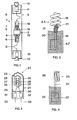
- the 70 W high-pressure discharge lamp 1 shown in FIG. 1 consists of a discharge vessel 2 made of quartz glass, which is squeezed on both sides and is enclosed by an outer bulb 3.
- the electrodes 4, 5 - shown schematically - are melted gas-tight into the discharge vessel 2 by means of foils 6, 7 and via the current leads 8, 9, the sealing foils 10, 11 of the outer bulb 3 and via further short current leads with the electrical connections of the ceramic base (R7s ) 12, 1.3 connected.
- a getter material 14 applied to a metal plate is additionally melted potential-free via a piece of wire.
- the ends 15, 16 of the discharge vessel 2 are provided with a heat-reflecting coating.
- the discharge vessel 2 contains metal iodides and bromides of sodium, tin, thallium, indium and lithium as the filling.
- the lamp 1 - with a power consumption of 70 W - has a luminous efficacy of 70 1m / W at a nominal current of 0.9 A.
- FIG. 2 shows an electrode 4, 5 with an enveloping protective filament 17, as is installed in the high-pressure discharge lamp 1 according to FIG. 1.
- the electrode 4, 5 itself consists of a single piece of wire with a Wire diameter of 0.4 mm. It is composed of a shaft part 18 of 4.9 mm in length and a helical part 19 with 3 1/2 turns of 2.7 mm in height. The clear width between the individual turns of the spiral part 19 - with an inner diameter of 1 mm - is 0.15 to 0.25 mm.
- the electrode 4, 5 consists of tungsten, which is enriched with 0.7% thorium dioxide and contains no emitter.
- the protective helix 17 is made of pure tungsten wire with a wire diameter of 0.1 mm and, with its fourteen closely adjacent turns, has a height of 1.4 mm.
- the protective helix 17 is conically shaped, the opening angle being 2.
- One end 20 of the protective helix with the smaller inside diameter of 0.35 mm (before assembly) adheres firmly to the shaft part 18 and is melted into the discharge vessel 2 with one turn.
- the other end 21 of the protective coil 17 with the larger inner diameter is pulled over the first bend of the coil part 19 of the electrode 4, 5.
- FIG. 3 shows the structure of a discharge vessel 22 made of quartz glass and squeezed on one side of a high-pressure discharge lamp according to the invention with a power consumption of approximately 35 W.
- the electrodes 23, 24 - shown schematically - are melted into the discharge vessel 22 and connected to the power supply lines 27, 28 via sealing foils 25, 26.
- the filling elements of the discharge vessel 22 correspond to those of the 70 W high-pressure discharge lamp 1 listed above.
- FIG. 4 shows an electrode 23 of the discharge vessel 22 squeezed on one side according to FIG. 3.
- the electrode 23 with a height of 8 mm consists of a single one Wire piece with a wire diameter of 0.25 mm. It has a shaft part 29 and a spiral part 30 with 2 1/4 turns, the latter having a height of 0.9 mm.
- the clear width between the individual turns of the spiral part 30 - with an inner diameter of 0.3 mm - is 0.1 mm.
- the helical part 30 is angled by 90 relative to the shaft part 29.
- This electrode 23 also consists of tungsten enriched with 0.7% thorium dioxide and contains no emitter.
Landscapes
- Discharge Lamp (AREA)
- Discharge Lamps And Accessories Thereof (AREA)
Applications Claiming Priority (2)
| Application Number | Priority Date | Filing Date | Title |
|---|---|---|---|
| DE3214642 | 1982-04-20 | ||
| DE3214642 | 1982-04-20 |
Publications (3)
| Publication Number | Publication Date |
|---|---|
| EP0092221A2 true EP0092221A2 (fr) | 1983-10-26 |
| EP0092221A3 EP0092221A3 (en) | 1984-07-04 |
| EP0092221B1 EP0092221B1 (fr) | 1988-07-20 |
Family
ID=6161423
Family Applications (1)
| Application Number | Title | Priority Date | Filing Date |
|---|---|---|---|
| EP83103744A Expired EP0092221B1 (fr) | 1982-04-20 | 1983-04-18 | Lampe à décharge à haute pression de bas pouvoir |
Country Status (2)
| Country | Link |
|---|---|
| US (1) | US4633136A (fr) |
| EP (1) | EP0092221B1 (fr) |
Cited By (2)
| Publication number | Priority date | Publication date | Assignee | Title |
|---|---|---|---|---|
| EP0220673A3 (en) * | 1985-10-24 | 1989-05-10 | Patent-Treuhand-Gesellschaft Fur Elektrische Gluhlampen Mbh | High-pressure discharge lamp |
| CN105505830A (zh) * | 2016-01-20 | 2016-04-20 | 山东科技大学 | 一株产生物表面活性剂的不动杆菌株及其应用 |
Families Citing this family (13)
| Publication number | Priority date | Publication date | Assignee | Title |
|---|---|---|---|---|
| DE3640990A1 (de) * | 1986-12-01 | 1988-06-16 | Patent Treuhand Ges Fuer Elektrische Gluehlampen Mbh | Einseitig gequetschte hochdruckentladungslampe |
| DE3641045A1 (de) * | 1986-12-01 | 1988-06-09 | Patent Treuhand Ges Fuer Elektrische Gluehlampen Mbh | Einseitig gequetschte hochdruckentladungslampe |
| US4998036A (en) * | 1987-12-17 | 1991-03-05 | Kabushiki Kaisha Toshiba | Metal vapor discharge lamp containing an arc tube with particular bulb structure |
| DE8805183U1 (de) * | 1988-04-19 | 1988-07-14 | Patent-Treuhand-Gesellschaft für elektrische Glühlampen mbH, 8000 München | Hochdruckentladungslampe |
| US4950954A (en) * | 1988-12-07 | 1990-08-21 | Gte Products Corporation | Metal halide discharge lamp with electrodes having unequal thoria contents |
| JPH0531801Y2 (fr) * | 1990-01-29 | 1993-08-16 | ||
| US5144201A (en) * | 1990-02-23 | 1992-09-01 | Welch Allyn, Inc. | Low watt metal halide lamp |
| DE4008375A1 (de) * | 1990-03-15 | 1991-09-19 | Patent Treuhand Ges Fuer Elektrische Gluehlampen Mbh | Hochdruckentladungslampe |
| DE4325679A1 (de) * | 1993-07-30 | 1995-02-02 | Patent Treuhand Ges Fuer Elektrische Gluehlampen Mbh | Elektrische Lampe mit Halogenfüllung |
| US6759806B2 (en) * | 2000-03-13 | 2004-07-06 | Nec Microwave Tube, Ltd. | High pressure discharge lamp and method for sealing a bulb thereof |
| JP3596453B2 (ja) * | 2000-09-28 | 2004-12-02 | ウシオ電機株式会社 | ショートアーク放電ランプ |
| US20090296400A1 (en) * | 2004-12-17 | 2009-12-03 | Masaru Ikeda | High-pressure mercury lamp, lamp unit, and image display apparatus |
| WO2008072159A2 (fr) * | 2006-12-13 | 2008-06-19 | Koninklijke Philips Electronics N.V. | Lampe avec fils d'alimentation dépassant de la lampe |
Family Cites Families (13)
| Publication number | Priority date | Publication date | Assignee | Title |
|---|---|---|---|---|
| CA577060A (fr) * | 1959-06-02 | W. L. Cumming Harry | Lampes a decharge electrique | |
| US1680572A (en) * | 1927-05-31 | 1928-08-14 | Roy H Rundle | Luminescent tube |
| GB1005809A (en) * | 1962-07-26 | 1965-09-29 | Ass Elect Ind | Improvements relating to metal vapour electric discharge lamps |
| NL6411355A (fr) * | 1964-09-30 | 1966-03-31 | ||
| NL6703447A (fr) * | 1967-03-03 | 1968-09-04 | ||
| GB1242173A (en) * | 1969-02-17 | 1971-08-11 | Gen Electric Co Ltd | Improvements in or relating to electric discharge lamps |
| DE2363843A1 (de) * | 1973-12-21 | 1975-06-26 | Philips Patentverwaltung | Metalljodiddampf-entladungslampe |
| NL7611135A (nl) * | 1976-10-08 | 1978-04-11 | Philips Nv | Hogedrukontladingslamp. |
| NL7711134A (nl) * | 1976-10-19 | 1978-04-21 | Gen Electric Co Ltd | Elektrische hoge druk ontladingslamp. |
| GB2043331B (en) * | 1978-12-26 | 1982-11-17 | Gen Electric | Electrode for high pressure metal-vapour lamp |
| US4275329A (en) * | 1978-12-29 | 1981-06-23 | General Electric Company | Electrode with overwind for miniature metal vapor lamp |
| US4387319A (en) * | 1981-03-30 | 1983-06-07 | General Electric Company | Metal halide lamp containing ScI3 with added cadmium or zinc |
| US4415829A (en) * | 1981-08-13 | 1983-11-15 | Gte Products Corporation | Direct current operable arc lamp |
-
1983
- 1983-04-13 US US06/484,568 patent/US4633136A/en not_active Expired - Lifetime
- 1983-04-18 EP EP83103744A patent/EP0092221B1/fr not_active Expired
Cited By (2)
| Publication number | Priority date | Publication date | Assignee | Title |
|---|---|---|---|---|
| EP0220673A3 (en) * | 1985-10-24 | 1989-05-10 | Patent-Treuhand-Gesellschaft Fur Elektrische Gluhlampen Mbh | High-pressure discharge lamp |
| CN105505830A (zh) * | 2016-01-20 | 2016-04-20 | 山东科技大学 | 一株产生物表面活性剂的不动杆菌株及其应用 |
Also Published As
| Publication number | Publication date |
|---|---|
| EP0092221A3 (en) | 1984-07-04 |
| EP0092221B1 (fr) | 1988-07-20 |
| US4633136A (en) | 1986-12-30 |
Similar Documents
| Publication | Publication Date | Title |
|---|---|---|
| EP0092221B1 (fr) | Lampe à décharge à haute pression de bas pouvoir | |
| EP0802561B1 (fr) | Lampe halogène | |
| EP0602529B1 (fr) | Lampe de décharge à haute pression ayant un récipient céramique de décharge | |
| EP0335202B1 (fr) | Lampe à décharge à haute pression, en particulier lampe à vapeur de sodium à haute pression | |
| DE2641867A1 (de) | Elektrische entladungslampe | |
| DE2718642C2 (de) | Elektrode für eine Hochdruck-Metallhalogenidlampe | |
| EP0453652B1 (fr) | Lampe à décharge à haute pression | |
| EP0573880B1 (fr) | Lampe à décharge haute pression | |
| EP0269957B1 (fr) | Lampe à décharge à haute pression munie d'un pincement unique | |
| EP0269958B1 (fr) | Lampe à décharge à haute pression munie d'un pincement unique | |
| DE4008375A1 (de) | Hochdruckentladungslampe | |
| EP0825636A2 (fr) | Lampe à décharge haute pression | |
| DE20106002U1 (de) | Metallhalogenidlampe mit keramischem Entladungsgefäß | |
| DE3242840C2 (fr) | ||
| DE2753898A1 (de) | Hochintensive entladungslampe | |
| EP0759633B1 (fr) | Lampe à décharge à haute pression | |
| DE69314509T2 (de) | Hochdruckentladungslampe | |
| DE68920546T2 (de) | Bogenentladungslampe. | |
| DE8211290U1 (de) | Hochdruckentladungslampe mit kleiner leistung | |
| DE60100556T2 (de) | Entladungslampe | |
| DE3741566C2 (de) | Kompakte Niederdruckentladungslampe | |
| EP0184876A2 (fr) | Lampe à décharge à gaz à haute pression à électrode en fer blanc de tungstène | |
| EP1709668B1 (fr) | Lampe a decharge basse pression | |
| EP0555755A1 (fr) | Lampe à décharge haute pression | |
| DE3221439C2 (fr) |
Legal Events
| Date | Code | Title | Description |
|---|---|---|---|
| PUAI | Public reference made under article 153(3) epc to a published international application that has entered the european phase |
Free format text: ORIGINAL CODE: 0009012 |
|
| AK | Designated contracting states |
Designated state(s): DE FR GB IT |
|
| PUAL | Search report despatched |
Free format text: ORIGINAL CODE: 0009013 |
|
| AK | Designated contracting states |
Designated state(s): DE FR GB IT |
|
| 17P | Request for examination filed |
Effective date: 19840718 |
|
| RBV | Designated contracting states (corrected) |
Designated state(s): FR GB IT |
|
| GRAA | (expected) grant |
Free format text: ORIGINAL CODE: 0009210 |
|
| AK | Designated contracting states |
Kind code of ref document: B1 Designated state(s): FR GB IT |
|
| GBT | Gb: translation of ep patent filed (gb section 77(6)(a)/1977) | ||
| ET | Fr: translation filed | ||
| ITF | It: translation for a ep patent filed | ||
| PLBE | No opposition filed within time limit |
Free format text: ORIGINAL CODE: 0009261 |
|
| STAA | Information on the status of an ep patent application or granted ep patent |
Free format text: STATUS: NO OPPOSITION FILED WITHIN TIME LIMIT |
|
| 26N | No opposition filed | ||
| ITTA | It: last paid annual fee | ||
| REG | Reference to a national code |
Ref country code: GB Ref legal event code: IF02 |
|
| PGFP | Annual fee paid to national office [announced via postgrant information from national office to epo] |
Ref country code: GB Payment date: 20020409 Year of fee payment: 20 |
|
| PGFP | Annual fee paid to national office [announced via postgrant information from national office to epo] |
Ref country code: FR Payment date: 20020430 Year of fee payment: 20 |
|
| PG25 | Lapsed in a contracting state [announced via postgrant information from national office to epo] |
Ref country code: GB Free format text: LAPSE BECAUSE OF EXPIRATION OF PROTECTION Effective date: 20030417 |
|
| REG | Reference to a national code |
Ref country code: GB Ref legal event code: PE20 |