EP0335202B1 - Lampe à décharge à haute pression, en particulier lampe à vapeur de sodium à haute pression - Google Patents
Lampe à décharge à haute pression, en particulier lampe à vapeur de sodium à haute pression Download PDFInfo
- Publication number
- EP0335202B1 EP0335202B1 EP89104825A EP89104825A EP0335202B1 EP 0335202 B1 EP0335202 B1 EP 0335202B1 EP 89104825 A EP89104825 A EP 89104825A EP 89104825 A EP89104825 A EP 89104825A EP 0335202 B1 EP0335202 B1 EP 0335202B1
- Authority
- EP
- European Patent Office
- Prior art keywords
- closure element
- electrode
- ceramic
- discharge vessel
- discharge
- Prior art date
- Legal status (The legal status is an assumption and is not a legal conclusion. Google has not performed a legal analysis and makes no representation as to the accuracy of the status listed.)
- Expired - Lifetime
Links
- DGAQECJNVWCQMB-PUAWFVPOSA-M Ilexoside XXIX Chemical compound C[C@@H]1CC[C@@]2(CC[C@@]3(C(=CC[C@H]4[C@]3(CC[C@@H]5[C@@]4(CC[C@@H](C5(C)C)OS(=O)(=O)[O-])C)C)[C@@H]2[C@]1(C)O)C)C(=O)O[C@H]6[C@@H]([C@H]([C@@H]([C@H](O6)CO)O)O)O.[Na+] DGAQECJNVWCQMB-PUAWFVPOSA-M 0.000 title claims description 18
- 229910052708 sodium Inorganic materials 0.000 title claims description 18
- 239000011734 sodium Substances 0.000 title claims description 18
- 239000000919 ceramic Substances 0.000 claims description 43
- 239000000654 additive Substances 0.000 claims description 31
- 230000000996 additive effect Effects 0.000 claims description 31
- MJGFBOZCAJSGQW-UHFFFAOYSA-N mercury sodium Chemical compound [Na].[Hg] MJGFBOZCAJSGQW-UHFFFAOYSA-N 0.000 claims description 13
- 229910001023 sodium amalgam Inorganic materials 0.000 claims description 13
- 238000003860 storage Methods 0.000 claims description 7
- 229910010293 ceramic material Inorganic materials 0.000 claims description 2
- 229910052756 noble gas Inorganic materials 0.000 claims description 2
- 239000004020 conductor Substances 0.000 claims 1
- 229910052751 metal Inorganic materials 0.000 description 27
- 239000002184 metal Substances 0.000 description 27
- 229910000497 Amalgam Inorganic materials 0.000 description 13
- 229910052758 niobium Inorganic materials 0.000 description 7
- 239000010955 niobium Substances 0.000 description 7
- GUCVJGMIXFAOAE-UHFFFAOYSA-N niobium atom Chemical compound [Nb] GUCVJGMIXFAOAE-UHFFFAOYSA-N 0.000 description 7
- 238000010276 construction Methods 0.000 description 5
- 230000000694 effects Effects 0.000 description 4
- 230000007704 transition Effects 0.000 description 4
- 230000015572 biosynthetic process Effects 0.000 description 3
- 210000003298 dental enamel Anatomy 0.000 description 3
- 239000011521 glass Substances 0.000 description 3
- 238000009413 insulation Methods 0.000 description 3
- 238000000034 method Methods 0.000 description 3
- 230000002035 prolonged effect Effects 0.000 description 3
- 238000007789 sealing Methods 0.000 description 3
- 239000003795 chemical substances by application Substances 0.000 description 1
- 238000003197 gene knockdown Methods 0.000 description 1
- 239000004922 lacquer Substances 0.000 description 1
- 238000004519 manufacturing process Methods 0.000 description 1
- 229910001092 metal group alloy Inorganic materials 0.000 description 1
- 238000009877 rendering Methods 0.000 description 1
- 230000000717 retained effect Effects 0.000 description 1
- 238000000926 separation method Methods 0.000 description 1
- 238000004904 shortening Methods 0.000 description 1
- 238000005476 soldering Methods 0.000 description 1
- GUVRBAGPIYLISA-UHFFFAOYSA-N tantalum atom Chemical group [Ta] GUVRBAGPIYLISA-UHFFFAOYSA-N 0.000 description 1
Images
Classifications
-
- H—ELECTRICITY
- H01—ELECTRIC ELEMENTS
- H01J—ELECTRIC DISCHARGE TUBES OR DISCHARGE LAMPS
- H01J61/00—Gas-discharge or vapour-discharge lamps
- H01J61/02—Details
- H01J61/36—Seals between parts of vessels; Seals for leading-in conductors; Leading-in conductors
- H01J61/361—Seals between parts of vessel
- H01J61/363—End-disc seals or plug seals
Definitions
- the invention relates to a high-pressure discharge lamp, in particular high-pressure sodium vapor lamp, which has a tubular ceramic discharge vessel, in the interior of which electrodes and a filling containing an ionizable noble gas and a metal additive are arranged, and the ends of the ceramic discharge vessel, optionally in an integrated manner, closing on both sides Has end elements, a cold chamber for receiving the metal additive, in particular sodium amalgam, is formed in the end element or between the end element and the wall of the ceramic discharge vessel and the end face of the end element delimiting the interior of the discharge vessel has radial sections of different height levels.
- Discharge lamps are also known in which an ignition electrode is installed in the vicinity of the main electrode.
- the metallic additional components which are deposited between the two electrodes hinder the ignition-promoting function of the ignition electrode. (To promote the ignition process on the part of the ignition electrode, it is necessary for the main electrode to be electrically insulated from the adjacent ignition electrode)
- the glass enamel used for the soldering and the surface of the ceramic terminating element can become electrically conductive.
- the focal spot of the discharge arc that arises does not form on the tip of the electrode, but on the sealing lacquer that has become conductive or on the surface of the ceramic terminating element. After a short time, this effect leads to the ceramic material of the discharge vessel becoming damaged.
- Discharge lamps are also known in which the contact between the electrically conductive metallic additional components, e.g. the sodium amalgam, and the electrodes are prevented by a special sealing element.
- the electrically conductive metallic additional components e.g. the sodium amalgam
- GB-A 1 465 212 Another example of such a high-pressure discharge lamp is known from GB-A 1 465 212, according to which an annular gap is formed in the closing element of the discharge tube as a storage space for the amalgam.
- the dimensions of the gap are not determined in the description, and since the power supply, which is designed as a niobium tube, is surrounded by a gap and the temperature of which is low enough due to the thermal conductivity of the niobium tube, the metallic additional components can also be deposited there. With this construction, it cannot be avoided with desired reliability that the amalgam comes into contact with the electrode or with the feed line forming a unit.
- a ceramic closure element is known from HU-B-181 782 (US-A-4459509), which has a bag-shaped storage space for receiving the metallic additional component.
- the aim was that the coldest point of the discharge lamp is in the closure element (and not between the closure element and the wall of the discharge vessel) and that the metal additive is largely shielded from the discharge space.
- Such a high-pressure discharge lamp more precisely a high-pressure sodium vapor lamp
- DE-A1 -24 05 335 in which the conductive metal additive, the sodium amalgam, is shielded from the electrode by an additional ceramic separating element in order to operate to prevent any flickering.
- the structure of the end element very complicated. It has been shown that the complete shielding of the electrode against the metallic additional components is superfluous, as can be found in EP-B-74 188.
- the formation of a ceramic shoulder around the niobium tube recommended. The height of the shoulder is determined by the fact that it should not shield the amalgam from the electrode, but the smallest possible width ensures that the electrode body has sufficient heat capacity so that the amalgam does not deposit on it.
- the closing element of the discharge tube is formed such that an annular channel for receiving the amalgam is formed between the element and the wall of the discharge tube.
- the greatest depth of the channel can be equal to the inside diameter of the discharge tube.
- the electrically conductive termination element has an insulating layer on its end face delimiting the interior of the discharge vessel.
- the insulating layer is provided with radial sections of different height levels in such a way that it is suitable on the one hand for preventing discharge between the electrode and the conductive end element and on the other hand determines a cold chamber for receiving the metal additive.
- no measures have been taken to prevent the formation of a short-circuit current path between the electrode and the metal additive located in the cold chamber during lamp operation.
- the aim of the present invention is to avoid the above-mentioned problems also with high-pressure discharge lamps of low power or high end temperature, e.g. in high-pressure discharge lamps improved color rendering, in particular in the case of sodium vapor lamps, and to achieve that not only when the lamps are operated for a short time, but also after a long period of operation, there is no electrical connection between the electrode and the conductive additional element.
- the delimiting, i.e. the surface of the closure element that closes the interior of the discharge vessel is divided into surface elements of different height levels.
- This structure is determined by the fact that the distance between the surface of the conductive metal additive and the electrode or the power supply that forms a unit with it, measured on the surface of the terminating element, ensures insulation even during prolonged operation. In other words, the distance must be long enough to prevent electrical contact between the conductive metal additive and the electrode throughout the life of the lamp. It could be determined by means of tests that for this purpose the length of the route must be greater than 4 mm.
- the role of the length of the route was not recognized.
- the solutions that dealt with dimensions indicated the depth, perhaps also the width of hollows or the width of a shoulder.
- the surface of the ceramic terminating element was designed in such a way that the length of the path traveled from the metal additive, in particular sodium amalgam, to the power supply or electrode did not reach the size of 4 mm. It was feared that the electrode tip and the metal additive would differ too much remove. As an important parameter, the latter distance was already determined in GB-A 502 321 so that it advantageously makes up about 2 mm.
- the additional metal from the discharge space is not deposited near the power supply and there is no electrical connection between the conductive metal additive and the electrode or even after prolonged operation.
- the power supply unit forming a unit with the electrode. Apart from extreme cases, the corresponding concentration of the metal additive is maintained without additional means for heat reflection in the discharge space.
- the essence of the proposed solution is therefore in particular that the between the surface of the conductive metal additive and the electrode, or the current supply line which forms a unit with the latter and which is measured along the surface of the ceramic terminating element, is greater than 4 mm. In other words, the distance is more than 4 mm.
- An advantageous embodiment of the ceramic closure element consists in the use of two troughs and a protruding rib arranged between the troughs, the rib determining the so-called cold chamber with the wall of the discharge vessel.
- a further advantageous further development exists if the base areas of the troughs have different levels on both sides of the rib and in such a way that the base area of the trough lying closer to the wall of the discharge vessel is lower, as seen from the discharge space.
- the storage space in the ceramic end element, which forms the cold chamber is narrower than 2 mm, and if, in the case of discharge lamps of low power, the distance between the end of the electrode directed to discharge and the storage space of the metal additive, in particular the sodium amalgam, is less than three times the distance between the electrode and the wall of the discharge vessel, in particular less than 5 mm.
- the outer trough advantageously forms the cold chamber.
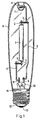
- the invention is used to improve high-pressure discharge lamps, in particular high-pressure sodium vapor lamps, a tubular ceramic discharge vessel 1 being arranged in a translucent outer bulb 8 (FIG. 1) and being connected to current leads 2 made of niobium.
- the power supply lines 2 of the ceramic discharge vessel 1 of the sodium vapor lamp shown in FIG. 1, which can be switched to a power source by a threaded base 11 or in another known manner, are coupled by supporting wires 3 to support elements 4, 5, which fix the ceramic discharge vessel in the outer bulb 8, whereby the discharge vessel 1 is fastened to an inner recess 7 of the outer bulb 8 with the aid of an elastic clip 6.
- the electric current flows to the discharge vessel 1 through the current leads 2 made of niobium, which, with the threaded part of the threaded base 11 and one located in the lower part of the threaded base 11, by means of the latter an insulation 12 electrically separated electrical contact 13 via a frame 10, power supply lines 9, the support elements 4, 5 and the support wires 3 are connected.
- the base structure is known per se and the lamp construction also requires no further detailed explanation.
- the innovation in the lamp construction according to the invention consists in a new design of the end part of the tubular ceramic discharge vessel 1, various advantageous embodiments of this end part being applicable, some of which can be seen as an example from FIGS. 2 to 6.
- the tubular discharge vessel 1 is provided with a ceramic end element 15 on at least one side, e.g. closed with a ceramic stopper, the broken surface delimiting the interior of the discharge vessel 1.
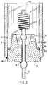
- This division is carried out, for example, according to FIG. 2, with a projecting rib 14 dividing the inner surface of the closure element 15 into an inner and an outer space. Therefore, the separation of a metal additive 16, in the given case the sodium amalgam from the power supply 2 is ensured.
- An inner trough 21 is advantageously formed in the central region of the closure element 15 and an outer trough 22 in the wall of the discharge vessel 1, i.e. 14 depressions are formed on both sides of the rib, one of which is provided for receiving the metal additive, for determining the cold chamber.
- an at least 4 mm long path 17, marked with a dash-dotted line, is determined as a path covered on the surface.
- the path 17 leads from the surface of the metal additive 16, which is located next to the wall of the ceramic discharge vessel 1 in the outer trough 22, over the metal additive-free one (Amalgam-free) surface of the rib 14 and the lower surface of the inner trough 21 up to the power supply 2.
- the power supply 2 is connected to an electrode 19 projecting into the interior of the discharge vessel.
- the wall of the discharge vessel 1 and the ceramic closure element 15 can be formed as an integrated component or the sealing of the discharge vessel is to be ensured by means of a glass enamel 18.
- the bottom of the outer trough 22 is, seen from the interior of the discharge vessel 1, advantageously lower than the bottom of the inner trough 21.
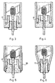
- the outstanding central rib 14, which plays an important role in determining the distance, can be designed with a cross section according to the given conditions. Some options can be seen in Figures 2 to 6.
- the embodiment of the solution according to the invention in which the distance between the tip of the electrode 19 and the surface of the metal additive 16 present in the ceramic terminating element 15 connected to the electrode 19 in the cold chamber is at most three times greater of the distance between the electrode 19 and the ceramic wall of the discharge vessel 1.
- the first distance is advantageously not greater than 5 mm.
- the cold chamber which advantageously has a width of less than 2 mm, can be determined by the ceramic wall of the discharge vessel 1 and the protruding rib 14.
- the rib 14 and the wall of the ceramic discharge vessel 1 can be made from one sintered ceramic body are formed, wherein the outer recess 22 receiving the metal additive is present in the body.
- the length of route 17 was also drawn here. In this case, the electrically conductive metal additive does not come into contact with the glass enamel (18).
- FIG. 4 shows a ceramic tube with a fully integrated termination, the electrode being inserted from the interior of the discharge vessel 1.
- a closure element 15 can be seen, which is designed to accommodate larger amounts of amalgam.
- the required amalgam temperature is determined by an external means 20 for heat shielding, e.g. ensured by a niobium plate.
Landscapes
- Vessels And Coating Films For Discharge Lamps (AREA)
- Discharge Lamps And Accessories Thereof (AREA)
- Discharge Lamp (AREA)
Claims (6)
- Lampe à décharge à haute pression, en particulier lampe à vapeur de sodium à haute pression, qui comprend un récipient à décharge de forme tubulaire en céramique dans le volume intérieur duquel sont disposés des électrodes (19) et un remplissage comprenant un gaz rare ionisable et un supplément de métal (16), et des éléments terminaux (15) obturant, le cas échéant de façon intégrée, les deux extrémités du récipient à décharge (1), une chambre froide recevant le supplément de métal (16), en particulier de l'amalgame de sodium, étant formée dans l'élément terminal (15) ou entre l'élément terminal (15) et la paroi du récipient à décharge (1) et la surface frontale de l'élément terminal délimitant le volume intérieur du récipient à décharge (1) présentant des parties radiales de différentes hauteurs, caractérisée en ce que l'élément terminal est composé d'un matériau céramique isolant électrique, en ce qu'au moins un alésage destiné à recevoir une alimentation électrique (2) de l'électrode (19) est réalisé dans l'élément terminal (15) et en ce que les parties radiales de la surface frontale de l'élément terminal (15) présentant des hauteurs différentes sont conformées de telle sorte que la distance (17) mesurée le long de la surface de l'élément terminal entre la surface du supplément de métal (16) se trouvant dans la chambre froide et l'électrode (19), respectivement l'alimentation électrique (2) formant un ensemble avec cette dernière, soit supérieure à 4 mm.
- Lampe à décharge à haute pression selon la revendication 1, caractérisée en ce que l'élément terminal (15) en céramique présente une nervure (14) dirigée vers le volume intérieur du récipient à décharge (1) qui divise la surface frontale de l'élément terminal (15) en une cuvette intérieure tournée vers l'électrode (19) et une cuvette extérieure opposée à l'électrode (19) et recevant le supplément de métal.
- Lampe à décharge à haute pression selon la revendication 2, caractérisée en ce que le fond de la cuvette extérieure (22) est situé plus bas que le fond de la cuvette intérieure (21).
- Lampe à décharge à haute pression selon l'une quelconque des revendications 1 à 3, caractérisée en ce que la chambre froide recevant le supplément de métal a la forme d'un volume de retenue d'une largeur allant jusqu'à 2 mm.
- Lampe à décharge à haute pression selon l'une quelconque des revendications 1 à 4, caractérisée en ce que l'écartement entre l'extrémité de l'électrode (19) sortant de l'élément terminal (15) et pénétrant dans le volume de décharge et le supplément de métal (16) présent dans la chambre froide, en particulier dans la cuvette extérieure (22), est au plus trois fois la longueur de l'écartement entre l'électrode (19) et la paroi du récipient à décharge (1).
- Lampe à décharge à haute pression selon la revendication 5, caractérisée en ce que l'écartement entre l'extrémité de l'électrode (19) sortant de l'élément terminal (15) et pénétrant dans le volume de décharge et le supplément de métal présent dans la chambre froide, en particulier dans la cuvette extérieure (22), est inférieur à 5 mm.
Applications Claiming Priority (2)
| Application Number | Priority Date | Filing Date | Title |
|---|---|---|---|
| HU881533A HU200031B (en) | 1988-03-28 | 1988-03-28 | High-pressure discharge lamp |
| HU153388 | 1988-03-28 |
Publications (3)
| Publication Number | Publication Date |
|---|---|
| EP0335202A2 EP0335202A2 (fr) | 1989-10-04 |
| EP0335202A3 EP0335202A3 (fr) | 1991-05-08 |
| EP0335202B1 true EP0335202B1 (fr) | 1995-07-12 |
Family
ID=10954910
Family Applications (1)
| Application Number | Title | Priority Date | Filing Date |
|---|---|---|---|
| EP89104825A Expired - Lifetime EP0335202B1 (fr) | 1988-03-28 | 1989-03-17 | Lampe à décharge à haute pression, en particulier lampe à vapeur de sodium à haute pression |
Country Status (5)
| Country | Link |
|---|---|
| US (1) | US4959588A (fr) |
| EP (1) | EP0335202B1 (fr) |
| JP (1) | JP2858777B2 (fr) |
| DE (1) | DE58909335D1 (fr) |
| HU (1) | HU200031B (fr) |
Families Citing this family (19)
| Publication number | Priority date | Publication date | Assignee | Title |
|---|---|---|---|---|
| EP0523249B1 (fr) * | 1991-02-04 | 1997-11-05 | Nkk Corporation | Procede d'inspection magnetique et dispositif prevu a cet effet |
| DE9112690U1 (de) * | 1991-10-11 | 1991-12-05 | Patent-Treuhand-Gesellschaft für elektrische Glühlampen mbH, 8000 München | Hochdruckentladungslampe |
| DE9206727U1 (de) * | 1992-05-18 | 1992-07-16 | Patent-Treuhand-Gesellschaft für elektrische Glühlampen mbH, 8000 München | Hochdruckentladungslampe |
| EP0609477B1 (fr) * | 1993-02-05 | 1999-05-06 | Patent-Treuhand-Gesellschaft für elektrische Glühlampen mbH | Enceinte céramique à décharge pour lampe à décharge à haute pression et sa méthode de fabrication et matériau d'étanchéité associé |
| JP3507179B2 (ja) * | 1995-01-13 | 2004-03-15 | 日本碍子株式会社 | 高圧放電灯 |
| US5729089A (en) * | 1996-05-17 | 1998-03-17 | Osram Sylvania Inc. | Electrode assembly for high pressure sodium lamp and method of making same |
| JP3419275B2 (ja) * | 1997-09-30 | 2003-06-23 | ウシオ電機株式会社 | 放電ランプのシール方法 |
| US6126889A (en) * | 1998-02-11 | 2000-10-03 | General Electric Company | Process of preparing monolithic seal for sapphire CMH lamp |
| US6731067B1 (en) * | 1999-09-10 | 2004-05-04 | General Electric Company | Elimination of weld in ceramic metal halide electrode-leadwire |
| DE60140883D1 (de) * | 2000-11-06 | 2010-02-04 | Koninkl Philips Electronics Nv | Hochdruckentladungslampe |
| US6759797B2 (en) * | 2001-06-15 | 2004-07-06 | General Electric Company | Compact fluorescent lamp |
| EP1701371A1 (fr) * | 2001-07-04 | 2006-09-13 | Fuji Photo Film Co., Ltd. | Procédé de fabrication d'électrodes |
| CA2422433A1 (fr) * | 2002-05-16 | 2003-11-16 | Walter P. Lapatovich | Lampe electrique avec reservoir a condensat et methode d'utilisation connexe |
| US20040056600A1 (en) * | 2002-09-19 | 2004-03-25 | Lapatovich Walter P. | Electric lamp with condensate reservoir and method of operation thereof |
| US7362041B2 (en) * | 2004-12-29 | 2008-04-22 | Osram Sylvania Inc. | Method of operating an arc discharge lamp and a lamp in which a salt reservoir site is locally cooled to provide a condensation site for iodine remote from the lamp's electrodes |
| JP4609479B2 (ja) * | 2007-10-23 | 2011-01-12 | ウシオ電機株式会社 | 光源装置 |
| DE102007061515A1 (de) * | 2007-12-20 | 2009-06-25 | Osram Gesellschaft mit beschränkter Haftung | Entladungsgefäß für eine Hochdruckentladungslampe |
| DE102009047753A1 (de) | 2009-12-09 | 2011-06-16 | Osram Gesellschaft mit beschränkter Haftung | Entladungsgefäß aus Keramik für eine Hochdruckentladungslampe |
| DE102013102600A1 (de) * | 2013-03-14 | 2014-10-02 | Heraeus Noblelight Gmbh | Quecksilberdampfentladungslampe und Verfahren zu deren Herstellung |
Citations (1)
| Publication number | Priority date | Publication date | Assignee | Title |
|---|---|---|---|---|
| HU181782B (en) * | 1981-01-09 | 1983-11-28 | Egyesuelt Izzolampa | Discharge vessel for high-pressure sodium-vapour discharge lamps |
Family Cites Families (5)
| Publication number | Priority date | Publication date | Assignee | Title |
|---|---|---|---|---|
| NL172194C (nl) * | 1973-02-16 | 1983-07-18 | Philips Nv | Hogedrukontladingslamp. |
| NL7311290A (nl) * | 1973-08-16 | 1975-02-18 | Philips Nv | Werkwijze voor het afsluiten van een ontladings- |
| JPS58140963A (ja) * | 1981-09-04 | 1983-08-20 | ソ−ン・イ−エムアイ・ピ−エルシ− | 高圧放電ランプ |
| US4742269A (en) * | 1984-11-09 | 1988-05-03 | Ngk Insulators, Ltd. | Ceramic envelope device for high-pressure discharge lamp |
| US4868457A (en) * | 1985-01-14 | 1989-09-19 | General Electric Company | Ceramic lamp end closure and inlead structure |
-
1988
- 1988-03-28 HU HU881533A patent/HU200031B/hu not_active IP Right Cessation
-
1989
- 1989-03-17 EP EP89104825A patent/EP0335202B1/fr not_active Expired - Lifetime
- 1989-03-17 DE DE58909335T patent/DE58909335D1/de not_active Expired - Fee Related
- 1989-03-23 US US07/327,892 patent/US4959588A/en not_active Expired - Lifetime
- 1989-03-27 JP JP1074792A patent/JP2858777B2/ja not_active Expired - Lifetime
Patent Citations (1)
| Publication number | Priority date | Publication date | Assignee | Title |
|---|---|---|---|---|
| HU181782B (en) * | 1981-01-09 | 1983-11-28 | Egyesuelt Izzolampa | Discharge vessel for high-pressure sodium-vapour discharge lamps |
Also Published As
| Publication number | Publication date |
|---|---|
| HUT49750A (en) | 1989-10-30 |
| DE58909335D1 (de) | 1995-08-17 |
| US4959588A (en) | 1990-09-25 |
| HU200031B (en) | 1990-03-28 |
| JPH0230051A (ja) | 1990-01-31 |
| JP2858777B2 (ja) | 1999-02-17 |
| EP0335202A2 (fr) | 1989-10-04 |
| EP0335202A3 (fr) | 1991-05-08 |
Similar Documents
| Publication | Publication Date | Title |
|---|---|---|
| EP0335202A2 (fr) | Lampe à décharge à haute pression, en particulier lampe à vapeur de sodium à haute pression | |
| DE3716485C1 (de) | Xenon-Kurzbogen-Entladungslampe | |
| DE69812069T2 (de) | Metallhalogenidlampe | |
| DE2405335C3 (de) | Hochdruckentladungslampe | |
| DE10243867A1 (de) | Quecksilberfreie Bogenentladungsröhre für Entladungslampeneinheit | |
| DE2641867A1 (de) | Elektrische entladungslampe | |
| EP0092221B1 (fr) | Lampe à décharge à haute pression de bas pouvoir | |
| EP1032022B1 (fr) | Lampe à halogénure métallique avec enveloppe céramique | |
| DE3429105C2 (fr) | ||
| EP2564479B1 (fr) | Eclateur | |
| EP0356840B1 (fr) | Lampe à décharge à haute pression | |
| EP0269958B1 (fr) | Lampe à décharge à haute pression munie d'un pincement unique | |
| DE102006007218A1 (de) | Hochdruckentladungslampe | |
| DE4008375A1 (de) | Hochdruckentladungslampe | |
| DE3200699C2 (de) | Entladungsgefäß für Hochdruck-Natriumdampflampen | |
| EP0446462A2 (fr) | Lampe à décharge à haute pression | |
| DE976223C (de) | Elektrische Hochdruck-Gasentladungslampe fuer Gleichstrombetrieb mit festen Gluehelektroden | |
| DE2102112A1 (de) | Hochdruck Gasentladungslampe | |
| DE8805183U1 (de) | Hochdruckentladungslampe | |
| EP1372184A2 (fr) | Système d'électrodes pour une lampe aux halogénures métalliques et lampe équipée d'un tel système | |
| DE3044121A1 (de) | Natriumhochdrucklampe | |
| DE2941114C2 (de) | Hochdruck-Natriumdampf-Entladungslampe | |
| DE1539498B2 (de) | Gasentladungslampe mit positiver Strom-Spannungs-Kennlinie | |
| DE10204925A1 (de) | Quecksilberfreie Hochdruckgasentladungslampe | |
| DE1539473A1 (de) | Hochdruck-Quecksilberdampflampe |
Legal Events
| Date | Code | Title | Description |
|---|---|---|---|
| PUAI | Public reference made under article 153(3) epc to a published international application that has entered the european phase |
Free format text: ORIGINAL CODE: 0009012 |
|
| AK | Designated contracting states |
Kind code of ref document: A2 Designated state(s): DE GB NL |
|
| PUAL | Search report despatched |
Free format text: ORIGINAL CODE: 0009013 |
|
| AK | Designated contracting states |
Kind code of ref document: A3 Designated state(s): DE GB NL |
|
| 17P | Request for examination filed |
Effective date: 19911107 |
|
| 17Q | First examination report despatched |
Effective date: 19930630 |
|
| GRAA | (expected) grant |
Free format text: ORIGINAL CODE: 0009210 |
|
| AK | Designated contracting states |
Kind code of ref document: B1 Designated state(s): DE GB NL |
|
| REF | Corresponds to: |
Ref document number: 58909335 Country of ref document: DE Date of ref document: 19950817 |
|
| GBT | Gb: translation of ep patent filed (gb section 77(6)(a)/1977) |
Effective date: 19950914 |
|
| PLBE | No opposition filed within time limit |
Free format text: ORIGINAL CODE: 0009261 |
|
| STAA | Information on the status of an ep patent application or granted ep patent |
Free format text: STATUS: NO OPPOSITION FILED WITHIN TIME LIMIT |
|
| 26N | No opposition filed | ||
| PGFP | Annual fee paid to national office [announced via postgrant information from national office to epo] |
Ref country code: GB Payment date: 20010212 Year of fee payment: 13 |
|
| PGFP | Annual fee paid to national office [announced via postgrant information from national office to epo] |
Ref country code: NL Payment date: 20010323 Year of fee payment: 13 |
|
| PGFP | Annual fee paid to national office [announced via postgrant information from national office to epo] |
Ref country code: DE Payment date: 20010529 Year of fee payment: 13 |
|
| REG | Reference to a national code |
Ref country code: GB Ref legal event code: IF02 |
|
| PG25 | Lapsed in a contracting state [announced via postgrant information from national office to epo] |
Ref country code: GB Free format text: LAPSE BECAUSE OF NON-PAYMENT OF DUE FEES Effective date: 20020317 |
|
| PG25 | Lapsed in a contracting state [announced via postgrant information from national office to epo] |
Ref country code: NL Free format text: LAPSE BECAUSE OF NON-PAYMENT OF DUE FEES Effective date: 20021001 Ref country code: DE Free format text: LAPSE BECAUSE OF NON-PAYMENT OF DUE FEES Effective date: 20021001 |
|
| GBPC | Gb: european patent ceased through non-payment of renewal fee |
Effective date: 20020317 |
|
| NLV4 | Nl: lapsed or anulled due to non-payment of the annual fee |
Effective date: 20021001 |