EP0092250A2 - Durch Druckflüssigkeit betätigtes Stellglied - Google Patents
Durch Druckflüssigkeit betätigtes Stellglied Download PDFInfo
- Publication number
- EP0092250A2 EP0092250A2 EP83103865A EP83103865A EP0092250A2 EP 0092250 A2 EP0092250 A2 EP 0092250A2 EP 83103865 A EP83103865 A EP 83103865A EP 83103865 A EP83103865 A EP 83103865A EP 0092250 A2 EP0092250 A2 EP 0092250A2
- Authority
- EP
- European Patent Office
- Prior art keywords
- piston
- piston member
- actuator
- fluid pressure
- screw shaft
- Prior art date
- Legal status (The legal status is an assumption and is not a legal conclusion. Google has not performed a legal analysis and makes no representation as to the accuracy of the status listed.)
- Granted
Links
Images

Classifications
-
- F—MECHANICAL ENGINEERING; LIGHTING; HEATING; WEAPONS; BLASTING
- F15—FLUID-PRESSURE ACTUATORS; HYDRAULICS OR PNEUMATICS IN GENERAL
- F15B—SYSTEMS ACTING BY MEANS OF FLUIDS IN GENERAL; FLUID-PRESSURE ACTUATORS, e.g. SERVOMOTORS; DETAILS OF FLUID-PRESSURE SYSTEMS, NOT OTHERWISE PROVIDED FOR
- F15B15/00—Fluid-actuated devices for displacing a member from one position to another; Gearing associated therewith
- F15B15/02—Mechanical layout characterised by the means for converting the movement of the fluid-actuated element into movement of the finally-operated member
- F15B15/06—Mechanical layout characterised by the means for converting the movement of the fluid-actuated element into movement of the finally-operated member for mechanically converting rectilinear movement into non- rectilinear movement
- F15B15/068—Mechanical layout characterised by the means for converting the movement of the fluid-actuated element into movement of the finally-operated member for mechanically converting rectilinear movement into non- rectilinear movement the motor being of the helical type
-
- F—MECHANICAL ENGINEERING; LIGHTING; HEATING; WEAPONS; BLASTING
- F16—ENGINEERING ELEMENTS AND UNITS; GENERAL MEASURES FOR PRODUCING AND MAINTAINING EFFECTIVE FUNCTIONING OF MACHINES OR INSTALLATIONS; THERMAL INSULATION IN GENERAL
- F16H—GEARING
- F16H25/00—Gearings comprising primarily only cams, cam-followers and screw-and-nut mechanisms
- F16H25/18—Gearings comprising primarily only cams, cam-followers and screw-and-nut mechanisms for conveying or interconverting oscillating or reciprocating motions
- F16H25/20—Screw mechanisms
- F16H25/22—Screw mechanisms with balls, rollers, or similar members between the co-operating parts; Elements essential to the use of such members
- F16H25/2204—Screw mechanisms with balls, rollers, or similar members between the co-operating parts; Elements essential to the use of such members with balls
Definitions
- This invention relates to a fluid pressure actuator and more particularly to a fluid pressure actuator comprising a cylinder containing a shaft rotatable by a fluid pressure, the cylinder per se preferably being adapted to expand and contract.
- the fluid pressure actuator according to this invention is operable by hydraulic pressure or pneumatic pressure, and drive for a piston member thereof may be the single-acting type or the double-acting type.
- Hydraulic rotary motors are broadly classified into vane system motors and piston system motors.
- the piston system motors include the rack and pinion type, the helical spline piston type, the piston chain type and the piston link type.
- helical spline type which has such a construction that, when a hydraulic pressure is applied to slide a piston mounted in a cylinder body, a helical spline slidable in unison with the piston imparts a rotational force on a helical spline in engagement therewith and rigidly attached to a rotary drive shaft.
- This helical spline piston type allows length of the helical splines to be determined freely and therefore the angle of rotation to be selected as desired. On the other hand, it has problems of requiring a great driving energy, of involving considerable energy losses and of its operation tending to be heavy.
- a known actuator providing a rotational movement, and expansion and contraction or linear movements generally utilizes a cylinder to carry out the expansion and contraction.
- the cylinder and a rotary part are in a very poor degree of organic combination. Therefore, its entire construction very much tends to be large, heavy and complicated.
- Such a known actuator also has a problem from a point of view of balance, and often loses smoothness of operation.
- This invention has been made in order to solve the above noted problems.
- an object of this invention is to provide a fluid pressure actuator comprising a cylinder body, a piston member mounted in the cylinder body to be axially movable and unrotatable relative thereto, a ball nut fixed to the piston member and axially aligned to a direction of movement of the piston member, the ball nut retaining a plurality of balls, and a screw shaft having a helical groove in engagement with the plurality of balls and mounted to be rotatable and axially immovable relative to the cylinder body, the screw shaft acting as a rotary drive shaft.
- a fluid pressure rotary motor comprises a tube body, a piston member mounted in the tube body to be axially movable and unrotatable relative thereto, a ball nut fixed to the piston member and axially aligned to a direction of movement of the piston member, the ball nut retaining a plurality of balls, and a screw shaft having a helical groove in engagement with the plurality of balls and mounted to be rotatable and axially immovable relative to the tube body, the fluid pressure rotary motor per se acting as a piston member mounted in a fluid pressure cylinder to be axially slidable relative thereto.
- the fluid pressure actuator according to this invention is operable under high precision control.
- This actuator is controlled with high precision with respect to both axial movements and angle of rotation particularly since a very slight axial movement can be converted at a greatly multiplied ratio into an angular movement.
- a ball nut is fixed to a piston member mounted in a cylinder body to be axially aligned to a direction of movement of the piston member, and a screw shaft in engagement with a plurality of balls retained by the ball nut is mounted to be rotatable and axially immovable relative to the cylinder body, the screw shaft acting as a rotary drive shaft.
- the ball screw instead of helical splines acts as converter of movement from linear movement to rotation.
- the angle of rotation ⁇ of the screw shaft is derived from an equation, wherein P is a pitch of the helical groove of the screw shaft, and L is an amount of movement of the piston member.
- P is a pitch of the helical groove of the screw shaft
- L is an amount of movement of the piston member.
- pitch P varies with the shaft diameter but, provided that the shaft diameter is the same, pitch P1 of a conventional helical spline is far greater than pitch P2 of the screw shaft according to this invention. Therefore, angle of rotation 02 is far greater than angle of rotation ⁇ 1 as derived from the above equation (1) when the amount of movement L is the same.
- X2 is far smaller than X1 as derived from the equation (2). It is to be noted that 81 and X1 represent those which pertains to the prior art and ⁇ 2 and X2 to the present invention.
- this invention facilitates precise control for the angle of rotation, and the shaft length may be shorter than in the prior art to obtain the same angle of rotation.
- the ball screw is capable of a very smooth movement with a far smaller frictional resistance.
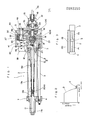
- a cylinder body 1 comprises a cylinder tube 2, a head cover 3, and a rod cover 4.
- Number 5 denotes a tie rod
- numbers 6 and 7 denote inlet and outlet ports of a pressure fluid, i.e. oil or air.
- a piston member 8 comprises a combination of a piston 9 and a telescopic rod 10. The piston member 8 is locked against rotation relative to the cylinder body 1 by suitable means to be described later.
- the telescopic rod 10 is the three-stage type and is supported at an extreme end thereof by a core element 11.
- the core element 11 is supported by an end cover 11a attached to the rod cover 4.
- Number 12 denotes a piston packing
- number 13 denotes a piston gasket
- number 13a denotes seal rings.
- a screw shaft 14 has one end thereof supported by the head cover 3 and the other end supported by the telescopic rod 10 and the core element 11.
- the screw shaft 14 comprises a helically grooved portion 15, a support portion 16 and an output portion 17.
- Number 18 denotes a press cover
- number 19 denotes a screw tube
- number 20 denotes bearings
- number 21 denotes packings.
- the support portion 16 includes a flange 22 held between the bearings 20, whereby the screw shaft 14 is locked against sliding movements relative to the cylinder body 1.
- a ball nut 23 is screwed to the piston 9 to be coaxial therewith, and retains a plurality of balls 24 in engagement with a helical groove of the screw shaft 14.
- the balls 24 circulate within the ball nut 23.
- the components so far described constitute a principal portion of the actuator.
- the actuator may be used with a rotation output member attached directly to the output shaft portion 17.
- the illustrated construction includes other components which are described hereinafter.
- a base plate 30 and a forward cover 31 are connected to each other at two sides through flanges, to form a gear box.
- a retainer 32 is secured to the forward plate 31 across an intermediate plate 33.
- the base plate 30 is secured to the press cover 18.
- An intermediate shaft 34 is splined to the output portion 17 of the screw shaft 14.'
- the intermediate shaft 34 is operatively connected to a final output shaft 36 through a reduction mechanism 35.
- the final output shaft 36 supports the intermediate shaft 34 to be coaxial and rotatable relative to each other.
- the reduction mechanism 35 shown is what is called harmonic drive which is compact and yet provides a great reduction ratio and includes no backlash.
- the harmonic drive itself is known and is therefore not described in detail.
- Number 37 denotes an electromagnetic brake
- number 38 denotes a pulse encoder.
- the electromagnetic brake 37 has a main body 39 secured to the base plate 30.
- the pulse encoder 38 is secured to a plate 40 which is secured to the base plate 30 through a plurality of tie rods 41.
- the electromagnetic brake 37 and the pulse encoder 38 have the following input arrangements.
- the intermediate shaft 34 carries a gear 42 fixed thereto which is in mesh with a gear 44 fixed to a driven shaft 43.
- the driven shaft 43 carries a magnetic disc 45 to be slidable and unrotatable relative thereto.
- the main body 39 contains an electromagnetic coil to draw the disc 45.
- the driven shaft 43 is connected through a flexible coupler 47 to an input shaft 46 of the pulse encoder 38.
- Numbers 48 and 49 denote bearings.
- This actuator operates as follows:
- the degree of precision is 0.0125 0 . It will be seen that the control is provided with a very high degree of precision.
- a microcomputer should preferably be used as the controller to which the pulse encoder 38 is connected.
- the electromagnetic brake 37 may be used for reduction D and inching E as shown in Fig. 2.
- an adjustment may preferably be effected by reversing a fluid pressure input direction by cooperation of the electromagnetic valve in the fluid circuit.
- the actuator may be provided with a pressure equalizing mechanism as shown in Fig. 3.
- This mechanism comprises a bypass 100 and a differential valve 101 which is operated on and off to make a pressure P1 and a pressure P2 substantially equal.
- the piston 9 is connected with the telescopic rod 10 instead of a piston rod, which has the following advantages.
- a piston rod would require a sealing structure at a perforation in the rod cover 4.
- a space must be provided to offer allowance when the piston rod is in an extreme protruding position.
- the telescopic rod does not involve such inconveniences but provides for compactness of the construction.
- the harmonic drive type reduction mechanism is used, a great reduction ratio, a great torque and an ultra-slow rotation are provided, and a backlash is not required.
- This actuator has a composite construction. More particularly, the fluid pressure actuator A according to the first embodiment already described acts as a piston member 55 in this embodiment which is mounted in a cylinder B to be axially movable relative thereto. Therefore, the actuator A has already been described, and the cylinder B will be described hereinafter.
- Number 50 denotes a cylinder tube
- number 51 denotes a head cover
- number 52 denotes a rod cover
- numbers 53 and 54 denote inlet and outlet ports of pressure fluid, i.e. oil or air.
- the actuator A constitutes the piston member 55 of the cylinder B as mentioned above.
- the principal portion of this piston member comprises the end cover 4 acting as a piston and the tube 2 acting as a piston rod.
- the tubes 50 and 2 are coaxial with each other.
- Number 56 denotes a piston packing.
- Number 57 denotes a pressure fluid feed pipe extending between the end covers 3 and 4 and through the piston 9.
- the piston 9 is slidable relative to the pipe 57.
- Number 58 denotes a seal ring.
- the piston 9 is held unrotatable by the pipe 57. Therefore the ball nut 23 also is held unrotatable thereby ensuring rotation of the screw shaft 14.
- the pipe 57 communicates with an inlet and outlet port 59.
- Number 60 denotes an electromagnetic brake
- number 61 denotes a pulse encoder.
- the brake 60 has a magnetic disc 62 and the pulse encoder 61 has an input shaft, both connected to a screw shaft 63.
- the screw shaft 63 is in engagement by means of a plurality of balls 64 with a ball nut 65 which is secured to an end of a tube 66.
- the tube 66 is slidably supported by a projecting portion 67 of the rod cover 52 and is secured to the base plate 30.
- the brake 60 and the pulse encoder 61 are attached to a base plate 68 which is attached to the head cover 51.
- the brake 60 and the pulse encoder 61 have the same constructions as the brake 37 and the pulse encoder 38 described earlier, and their description is omitted.
- the cylinder B merely expands and contracts and therefore its operation need not particularly be described.
- a slight axial movement of the fluid pressure actuator A which constitutes the piston member 55 of the cylinder B is converted at a greatly multiplied rate into an angle of rotation of the screw shaft 63 and that high precision signals are provided by the pulse encoder 61. Therefore, the slight axial movement is accurately controlled.
- a combined operation of the actuator A and the cylinder B comprises the following four different modes:
- Fig. 6 shows the composite actuator capable of expansion, contraction and swivelling as applied to a robotic arm 70 which is one example of application.
- this invention provides actuators whose rotations are controlled with high precision and which operate smoothly, whereby driving energy therefor may be saved.
- the invention achieves compactness of construction also.
Landscapes
- Engineering & Computer Science (AREA)
- General Engineering & Computer Science (AREA)
- Mechanical Engineering (AREA)
- Physics & Mathematics (AREA)
- Fluid Mechanics (AREA)
- Actuator (AREA)
- Fluid-Driven Valves (AREA)
- Transmission Devices (AREA)
Priority Applications (1)
| Application Number | Priority Date | Filing Date | Title |
|---|---|---|---|
| AT83103865T ATE24580T1 (de) | 1982-04-20 | 1983-04-20 | Durch druckfluessigkeit betaetigtes stellglied. |
Applications Claiming Priority (2)
| Application Number | Priority Date | Filing Date | Title |
|---|---|---|---|
| JP66527/82 | 1982-04-20 | ||
| JP57066527A JPS58184302A (ja) | 1982-04-20 | 1982-04-20 | 伸縮旋回装置 |
Publications (3)
| Publication Number | Publication Date |
|---|---|
| EP0092250A2 true EP0092250A2 (de) | 1983-10-26 |
| EP0092250A3 EP0092250A3 (en) | 1984-04-25 |
| EP0092250B1 EP0092250B1 (de) | 1986-12-30 |
Family
ID=13318429
Family Applications (1)
| Application Number | Title | Priority Date | Filing Date |
|---|---|---|---|
| EP83103865A Expired EP0092250B1 (de) | 1982-04-20 | 1983-04-20 | Durch Druckflüssigkeit betätigtes Stellglied |
Country Status (5)
| Country | Link |
|---|---|
| US (1) | US4509408A (de) |
| EP (1) | EP0092250B1 (de) |
| JP (1) | JPS58184302A (de) |
| AT (1) | ATE24580T1 (de) |
| DE (1) | DE3368728D1 (de) |
Cited By (2)
| Publication number | Priority date | Publication date | Assignee | Title |
|---|---|---|---|---|
| EP0697061A4 (de) * | 1993-04-27 | 1996-04-03 | ||
| CN107165885A (zh) * | 2017-06-23 | 2017-09-15 | 杭州加包装技术有限责任公司 | 一种调节气缸轴向位置的机构 |
Families Citing this family (18)
| Publication number | Priority date | Publication date | Assignee | Title |
|---|---|---|---|---|
| GB2159599B (en) * | 1984-03-22 | 1987-02-18 | Smiths Industries Plc | Actuators |
| US4776230A (en) * | 1986-04-18 | 1988-10-11 | Susnjara Kenneth J | Actuator assembly for industrial robots |
| US4876906A (en) * | 1986-11-20 | 1989-10-31 | Sundstrand Corporation | Non-jamming actuator system |
| DE4222097A1 (de) * | 1992-07-07 | 1994-01-13 | Ivan Tarabaric | Schrittantrieb, druckmediumbetätigbar |
| US5570769A (en) * | 1992-12-14 | 1996-11-05 | Turn Act, Inc. | Linear and rotary actuator combination |
| US5404983A (en) * | 1992-12-14 | 1995-04-11 | Eicher; Fred C. | Turn-act multiaction device |
| JPH06300106A (ja) * | 1993-04-10 | 1994-10-28 | T H K Kk | 電動アクチュエータ |
| DE10108156A1 (de) * | 2001-02-20 | 2002-08-29 | Basf Ag | Rylenderivate |
| US6578897B2 (en) * | 2001-03-01 | 2003-06-17 | Aero Industries, Inc. | Deployment mechanism for tarping system |
| DE102004055306B4 (de) * | 2003-11-21 | 2007-06-14 | Smc K.K. | Stellglied |
| US8413572B1 (en) | 2006-11-22 | 2013-04-09 | Westendorf Manufacturing, Co. | Auto attachment coupler with abductor valve |
| JP5235729B2 (ja) * | 2009-03-10 | 2013-07-10 | 株式会社神戸製鋼所 | 樹脂造粒装置 |
| CN101701594B (zh) * | 2009-10-27 | 2011-09-28 | 淮海工学院 | 独立可控大转角电液伺服摆动液压缸 |
| DE102015221712B4 (de) * | 2015-11-05 | 2025-04-17 | Robert Bosch Gmbh | Aktuator mit Kühlkanälen, in die von der Mutter Fluid förderbar ist |
| CN106194882A (zh) * | 2016-07-08 | 2016-12-07 | 彭东林 | 一种数字液压缸 |
| CN106678324A (zh) * | 2016-12-08 | 2017-05-17 | 中船重工中南装备有限责任公司 | 输出扭矩的液压装置 |
| US10935053B2 (en) * | 2018-10-26 | 2021-03-02 | Ellrich Engineering, Llc | Space-constrained hybrid linear actuator |
| CN110541864B (zh) * | 2019-08-29 | 2024-05-28 | 上海布拓传动系统设备有限公司 | 一种带制动器集成编码器的液压马达 |
Family Cites Families (12)
| Publication number | Priority date | Publication date | Assignee | Title |
|---|---|---|---|---|
| US2197155A (en) * | 1938-09-10 | 1940-04-16 | Bendix Aviat Corp | Screw mechanism |
| GB890440A (en) * | 1959-05-01 | 1962-02-28 | John Cecil Ridley | Fluid-pressure-operated actuator |
| US2955579A (en) * | 1959-09-04 | 1960-10-11 | Bachan Mfg Company | Fluid actuator for linear and rotary movements |
| US3920084A (en) * | 1973-11-21 | 1975-11-18 | Jr Wayne B Russell | Extendable and retractible material delivery devices |
| ATA387978A (de) * | 1978-05-29 | 1982-08-15 | Ife Gmbh | Drehantrieb fuer tueren od.dgl. |
| JPS5520970A (en) * | 1978-08-01 | 1980-02-14 | Tsuda Tekkosho:Kk | Stroke variable cylinder |
| SU920280A1 (ru) * | 1978-09-05 | 1982-04-15 | за витель В. X. Подойницын | Гидроцилиндр |
| JPS5676705A (en) * | 1979-11-29 | 1981-06-24 | Miyoutoku:Kk | Control system for air cylinder |
| US4325535A (en) * | 1980-03-26 | 1982-04-20 | Baker Cac, Inc. | Actuator mechanism for a rotary valve or the like |
| GB2076469A (en) * | 1980-04-29 | 1981-12-02 | Secretary Industry Brit | Fluid actuated ram with position measuring device |
| US4409888A (en) * | 1980-05-02 | 1983-10-18 | Weyer Paul P | Combined linear and rotary actuator and floating ring gear |
| WO1982004293A1 (en) * | 1981-05-28 | 1982-12-09 | Archer John Richard | Hydraulic linear actuator |
-
1982
- 1982-04-20 JP JP57066527A patent/JPS58184302A/ja active Pending
-
1983
- 1983-04-20 AT AT83103865T patent/ATE24580T1/de active
- 1983-04-20 EP EP83103865A patent/EP0092250B1/de not_active Expired
- 1983-04-20 DE DE8383103865T patent/DE3368728D1/de not_active Expired
- 1983-04-20 US US06/486,772 patent/US4509408A/en not_active Expired - Lifetime
Cited By (3)
| Publication number | Priority date | Publication date | Assignee | Title |
|---|---|---|---|---|
| EP0697061A4 (de) * | 1993-04-27 | 1996-04-03 | ||
| CN107165885A (zh) * | 2017-06-23 | 2017-09-15 | 杭州加包装技术有限责任公司 | 一种调节气缸轴向位置的机构 |
| CN107165885B (zh) * | 2017-06-23 | 2018-11-06 | 杭州加一包装技术有限责任公司 | 一种调节气缸轴向位置的机构 |
Also Published As
| Publication number | Publication date |
|---|---|
| US4509408A (en) | 1985-04-09 |
| EP0092250B1 (de) | 1986-12-30 |
| ATE24580T1 (de) | 1987-01-15 |
| DE3368728D1 (en) | 1987-02-05 |
| EP0092250A3 (en) | 1984-04-25 |
| JPS58184302A (ja) | 1983-10-27 |
Similar Documents
| Publication | Publication Date | Title |
|---|---|---|
| US4509408A (en) | Fluid pressure actuator | |
| JP3574820B2 (ja) | 差動式リニヤ・アクチュエータ | |
| EP2079944B1 (de) | Vorrichtung zum betätigen eines als losrad ausgeführten zahnrades einer getriebeeinrichtung | |
| US4409888A (en) | Combined linear and rotary actuator and floating ring gear | |
| EP0706631A1 (de) | Sonnennachführung | |
| EP0177876B1 (de) | Linearantrieb | |
| US4748866A (en) | Linear helical actuator | |
| US4939983A (en) | Fluid pressure operated positioning apparatus | |
| EP1187967B1 (de) | Stellantrieb | |
| US3722371A (en) | High ratio linkage mechanism | |
| KR20210094542A (ko) | 각 전동 장치 | |
| US3899956A (en) | Linear electrohydraulic pulse drive actuator | |
| DE69422982T2 (de) | Rotationsschalter mit externen lagern | |
| HU177203B (en) | Working roll | |
| US4901627A (en) | Hydraulic idling-regulating valve | |
| JPH0348054A (ja) | アクチュエータ | |
| GB2112967A (en) | Hydraulic valve control and feedback utilizing a harmonic drive differential | |
| EP3835201B1 (de) | Hydraulisches betätigungssystem zur verminderung der rotation | |
| WO1987000590A1 (en) | Rotary actuator | |
| US3174351A (en) | Drive mechanism | |
| DE4419244A1 (de) | Sonnennachführung | |
| US4582183A (en) | Sliding displacement detecting apparatus | |
| EP4058705B1 (de) | Betätigungsvorrichtung für ein absperrventil | |
| JPH0159401B2 (de) | ||
| GB2038672A (en) | Feed drive system |
Legal Events
| Date | Code | Title | Description |
|---|---|---|---|
| PUAI | Public reference made under article 153(3) epc to a published international application that has entered the european phase |
Free format text: ORIGINAL CODE: 0009012 |
|
| AK | Designated contracting states |
Designated state(s): AT BE CH DE FR GB IT LI LU NL SE |
|
| PUAL | Search report despatched |
Free format text: ORIGINAL CODE: 0009013 |
|
| AK | Designated contracting states |
Designated state(s): AT BE CH DE FR GB IT LI LU NL SE |
|
| 17P | Request for examination filed |
Effective date: 19840228 |
|
| GRAA | (expected) grant |
Free format text: ORIGINAL CODE: 0009210 |
|
| AK | Designated contracting states |
Kind code of ref document: B1 Designated state(s): AT BE CH DE FR GB IT LI LU NL SE |
|
| REF | Corresponds to: |
Ref document number: 24580 Country of ref document: AT Date of ref document: 19870115 Kind code of ref document: T |
|
| REF | Corresponds to: |
Ref document number: 3368728 Country of ref document: DE Date of ref document: 19870205 |
|
| ITF | It: translation for a ep patent filed | ||
| ET | Fr: translation filed | ||
| PG25 | Lapsed in a contracting state [announced via postgrant information from national office to epo] |
Ref country code: LU Free format text: LAPSE BECAUSE OF NON-PAYMENT OF DUE FEES Effective date: 19870430 |
|
| PGFP | Annual fee paid to national office [announced via postgrant information from national office to epo] |
Ref country code: NL Payment date: 19870430 Year of fee payment: 5 |
|
| PLBE | No opposition filed within time limit |
Free format text: ORIGINAL CODE: 0009261 |
|
| STAA | Information on the status of an ep patent application or granted ep patent |
Free format text: STATUS: NO OPPOSITION FILED WITHIN TIME LIMIT |
|
| 26N | No opposition filed | ||
| PG25 | Lapsed in a contracting state [announced via postgrant information from national office to epo] |
Ref country code: AT Effective date: 19880420 |
|
| PG25 | Lapsed in a contracting state [announced via postgrant information from national office to epo] |
Ref country code: LI Effective date: 19880430 Ref country code: CH Effective date: 19880430 |
|
| PG25 | Lapsed in a contracting state [announced via postgrant information from national office to epo] |
Ref country code: NL Effective date: 19881101 |
|
| NLV4 | Nl: lapsed or anulled due to non-payment of the annual fee | ||
| REG | Reference to a national code |
Ref country code: CH Ref legal event code: PL |
|
| ITTA | It: last paid annual fee | ||
| PGFP | Annual fee paid to national office [announced via postgrant information from national office to epo] |
Ref country code: FR Payment date: 19920312 Year of fee payment: 10 |
|
| PGFP | Annual fee paid to national office [announced via postgrant information from national office to epo] |
Ref country code: GB Payment date: 19920414 Year of fee payment: 10 |
|
| PGFP | Annual fee paid to national office [announced via postgrant information from national office to epo] |
Ref country code: SE Payment date: 19920416 Year of fee payment: 10 Ref country code: BE Payment date: 19920416 Year of fee payment: 10 |
|
| PGFP | Annual fee paid to national office [announced via postgrant information from national office to epo] |
Ref country code: DE Payment date: 19920610 Year of fee payment: 10 |
|
| PG25 | Lapsed in a contracting state [announced via postgrant information from national office to epo] |
Ref country code: GB Effective date: 19930420 |
|
| PG25 | Lapsed in a contracting state [announced via postgrant information from national office to epo] |
Ref country code: SE Effective date: 19930421 |
|
| PG25 | Lapsed in a contracting state [announced via postgrant information from national office to epo] |
Ref country code: BE Effective date: 19930430 |
|
| BERE | Be: lapsed |
Owner name: KOWA SHOJI LTD. Effective date: 19930430 |
|
| GBPC | Gb: european patent ceased through non-payment of renewal fee |
Effective date: 19930420 |
|
| PG25 | Lapsed in a contracting state [announced via postgrant information from national office to epo] |
Ref country code: FR Effective date: 19931229 |
|
| PG25 | Lapsed in a contracting state [announced via postgrant information from national office to epo] |
Ref country code: DE Effective date: 19940101 |
|
| REG | Reference to a national code |
Ref country code: FR Ref legal event code: ST |
|
| EUG | Se: european patent has lapsed |
Ref document number: 83103865.8 Effective date: 19931110 |