EP0092473A1 - Vorrichtung zur Abgabe in regulierbaren Proportionen zweier dickflüssiger Substanzen - Google Patents
Vorrichtung zur Abgabe in regulierbaren Proportionen zweier dickflüssiger Substanzen Download PDFInfo
- Publication number
- EP0092473A1 EP0092473A1 EP83400740A EP83400740A EP0092473A1 EP 0092473 A1 EP0092473 A1 EP 0092473A1 EP 83400740 A EP83400740 A EP 83400740A EP 83400740 A EP83400740 A EP 83400740A EP 0092473 A1 EP0092473 A1 EP 0092473A1
- Authority
- EP
- European Patent Office
- Prior art keywords
- distributor
- cage
- outlets
- outlet
- orifice
- Prior art date
- Legal status (The legal status is an assumption and is not a legal conclusion. Google has not performed a legal analysis and makes no representation as to the accuracy of the status listed.)
- Granted
Links
- 235000011837 pasties Nutrition 0.000 title claims abstract description 21
- 239000000463 material Substances 0.000 title description 2
- 238000001125 extrusion Methods 0.000 claims abstract description 28
- 239000000126 substance Substances 0.000 claims abstract description 17
- 239000007787 solid Substances 0.000 claims description 9
- 239000000546 pharmaceutical excipient Substances 0.000 abstract description 3
- 239000000203 mixture Substances 0.000 description 2
- 238000007789 sealing Methods 0.000 description 2
- 239000013543 active substance Substances 0.000 description 1
- 239000011324 bead Substances 0.000 description 1
- 239000006071 cream Substances 0.000 description 1
- 238000004519 manufacturing process Methods 0.000 description 1
- 239000007769 metal material Substances 0.000 description 1
- 238000005192 partition Methods 0.000 description 1
- 230000002093 peripheral effect Effects 0.000 description 1
Images


Classifications
-
- B—PERFORMING OPERATIONS; TRANSPORTING
- B65—CONVEYING; PACKING; STORING; HANDLING THIN OR FILAMENTARY MATERIAL
- B65D—CONTAINERS FOR STORAGE OR TRANSPORT OF ARTICLES OR MATERIALS, e.g. BAGS, BARRELS, BOTTLES, BOXES, CANS, CARTONS, CRATES, DRUMS, JARS, TANKS, HOPPERS, FORWARDING CONTAINERS; ACCESSORIES, CLOSURES, OR FITTINGS THEREFOR; PACKAGING ELEMENTS; PACKAGES
- B65D47/00—Closures with filling and discharging, or with discharging, devices
- B65D47/04—Closures with discharging devices other than pumps
- B65D47/20—Closures with discharging devices other than pumps comprising hand-operated members for controlling discharge
- B65D47/30—Closures with discharging devices other than pumps comprising hand-operated members for controlling discharge with plug valves, i.e. valves that open and close a passageway by turning a cylindrical or conical plug without axial passageways
-
- B—PERFORMING OPERATIONS; TRANSPORTING
- B65—CONVEYING; PACKING; STORING; HANDLING THIN OR FILAMENTARY MATERIAL
- B65D—CONTAINERS FOR STORAGE OR TRANSPORT OF ARTICLES OR MATERIALS, e.g. BAGS, BARRELS, BOTTLES, BOXES, CANS, CARTONS, CRATES, DRUMS, JARS, TANKS, HOPPERS, FORWARDING CONTAINERS; ACCESSORIES, CLOSURES, OR FITTINGS THEREFOR; PACKAGING ELEMENTS; PACKAGES
- B65D35/00—Pliable tubular containers adapted to be permanently or temporarily deformed to expel contents, e.g. collapsible tubes for toothpaste or other plastic or semi-liquid material; Holders therefor
- B65D35/24—Pliable tubular containers adapted to be permanently or temporarily deformed to expel contents, e.g. collapsible tubes for toothpaste or other plastic or semi-liquid material; Holders therefor with auxiliary devices
- B65D35/242—Pliable tubular containers adapted to be permanently or temporarily deformed to expel contents, e.g. collapsible tubes for toothpaste or other plastic or semi-liquid material; Holders therefor with auxiliary devices for mixing or discharging of two or more components
Definitions
- the present invention relates to a device for dispensing pasty substances.
- European patent 0 004 821 a device for the distribution in adjustable proportion of two pasty substances contained separately inside a deformable tube provided with an outlet orifice, comprising a nozzle adaptable on the orifice.
- outlet of the tube to define two chambers inside the tubes capable of containing the two pasty substances and two corresponding outlets opening onto an outlet surface of the nozzle; a distributor mounted pivoting on the nozzle around an axis perpendicular to the axis of the outlet of the tube between two extreme positions between which a cylindrical surface of the distributor sweeps the outlet surface of the nozzle, the distributor having one or two passages opening out through an inlet section into the cylindrical surface of the dispenser and ending in a common extrusion outlet, the inlet section or sections more or less releasing the two outlets from the outlet surface of the tip according to the pivoting position of the distributor.
- the common extrusion outlet is done by a common cannula secured to the dispenser and the angle of rotation of the latter is limited.
- the present invention aims to improve the operation of the device of the aforementioned French patent by notably increasing the angle of rotation of the distributor and by making it possible to obtain a more marked difference between the different positions of the distributor.
- the present invention also aims to improve the sealing of the dispenser and to improve its manufacture.
- the distributor is pivotally mounted inside a cylindrical cage integral with the end piece.
- the distributor passages are formed by two grooves formed in the cylindrical surface of the distributor and capable of communicating on the one hand with the two outputs of the nozzle and on the other hand with the cage extrusion hole.
- the passage of the distributor consists of a hollow formed through the distributor and limited on one side by a straight flank perpendicular to the axis of rotation of the distributor and on the other side by a flank of helical shape, the hollow communicating on the one hand with the two outlets of the nozzle and on the other hand with the extrusion orifice of the cage.
- the digging is interrupted by a solid part of the cylindrical surface of the distributor, intended to close the extrusion orifice of the cage when the distributor is in the closed position.
- the digging is interrupted by two opposite solid parts of the cylindrical surface of the distributor, intended to close the two outlets of the nozzle respectively, and the cage extrusion orifice when the dispenser is in the closed position.
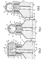
- the device shown in Figures 1 and 2 comprises a deformable tube 10, made for example of a metallic material or a plastic material and provided with an outlet orifice 12 externally threaded.
- a nozzle 14 which comprises a tube 16 plunging inside the tube, the lower end 18 of which reaches a height determined relative to the bottom of the tube (not shown) and the upper end of which leads to a part 20 of an outlet surface of the end piece 14 which has a cylindrical profile with an XY axis (cf. FIG. 1), this XY axis being in the plane of FIG. 1 and perpendicular to the plane of FIG. 2 .
- the tube 10 contains a first pasty substance 24 filling the tube 10 from the bottom to level 26 of the lower end 18 of the tubing 16. and a second pasty substance 28 filling the peripheral chamber delimited inside the tube 10 around tubing 16 and above level 26.
- the first pasty substance 24 tends to be extruded from the tube by the tube 16 while the second pasty substance 28 tends to be extruded simultaneously from the tube by the outlet 22.
- the proportion of the mixture of pasty substances 24 and 28 is obtained by a distributor 30 pivotally mounted inside a cage 32 secured to the end piece 14, around the aforementioned axis XY, and the cylindrical inner wall of which comprises the tip outlet surface.
- the cage 32 comprises a cylindrical surface which comprises on the one hand the aforementioned outlets 20 and 22 and on the other hand an extrusion orifice 34 intended to allow the extrusion of the mixture of the two pasty substances the proportion of which is adjusted by the distributor 30.
- the extrusion orifice 34 is situated substantially at 90 ° relative to the two outlets 20 and 22.
- the cage 32 has at one of its ends a bottom wall 36, while its opposite end is open to allow the introduction of the distributor 30.
- the latter has a generally cylindrical shape with an annular bead 38 cooperating with an annular groove 40 of cage 36, so that the distributor can rotate in the cage without being able move axially.
- the distributor 30 is rotated manually by an operating tab 42 which is arranged along a diameter of the distributor and which also serves as an indicator for the position of the distributor.
- the dispenser 30 has two passages allowing the distribution of the two pasty substances originating respectively from the two outlets 20 and 22 and their extrusion by the common outlet 34. These passages consist of two parallel grooves 44 and 46 formed in the cylindrical surface of the dispenser and separated by a partition 48.
- the groove 44 has a constant depth, while the groove 46 is made in a spiral so as to have a variable depth.
- the two grooves 44 and 46 are interrupted by a solid part 50 which extends over at least a quarter of the periphery of the distributor 30 (cf. FIG. 2). Thus, when the dispenser is in the closed position, the solid part 50 closes both the extrusion orifice 34 and the outlets 20 and 22 of the nozzle.
- the depth of the groove 46 of the level of the outlet 22 varies, which makes it possible to vary the relative proportion of the two pasty substances.
- the device of FIGS. 1 and 2 further comprises a shutter 52 in the form of a movable visor which pivots outside the cage 32 and which makes it possible to close the extrusion orifice 34 and to complete the sealing of the device when the dispenser is in the closed position.
- the shutter 52 is integral in rotation with the distributor 30 to which it is secured by means of the operating tab 42.
- the orifice 34 is disposed substantially at 90 ° relative to at outputs 20 and 22, which allows the distributor to rotate about 3/4 of a turn and thus ensure maximum travel of the distributor.
- the device shown in Figures 3 and 4 shows the main features of the device of Figures 1 and 2 and only the means of passage of the dispenser 30 are different.
- the distributor comprises a single passage constituted by a hollow 54 formed through the distributor 30. This digging is limited on one side by a rectilinear flank 56 perpendicular to the axis of rotation XY of the distributor and on the other side by a flank 58 of helical shape.
- the hollow 54 communicates with the two outlets 20 and 22 and with the extrusion orifice 34.
- the sides 56 and 58 are placed in such a way that the outlet 20 is always released and that the outlet 22 is more or less released, when the distributor 30 is not in the closed position.
- the digging 54 is interrupted by a solid part 60 of the cylindrical surface of the distributor which is intended to close the extrusion orifice 34 when the distributor is in closed function.
- the orifice 34 is substantially at right angles to the outlets 20 and 22 which allows to close a maximum clearance of the distributor.
- the device according to the variant shown in FIG. 5 differs from that of FIGS. 3 and 4 only in the position of the extrusion orifice 34 which is at 180 ° relative to the outlets 20 and 22, which limits the travel of the distributor 30 but allows more convenient use since the extrusion is then carried out at the top of the tube 10.
- FIGS. 6 and 7 The device represented in FIGS. 6 and 7 is practically identical to that of FIG. 5.
- the digging 54 is interrupted by two solid diametrically opposite parts 60 and 62 of the cylindrical surface of the distributor 30. This makes it possible to perfect the seal by simultaneously obstructing the outlets 20 and 22 and the orifice d extrusion 34 when the distri - striker is in the closed position.
- FIGS. 3 to 7 can also be provided with the shutter 52 of the device of FIGS. 1 and 2.
- the device of the invention makes it possible to distribute, in adjustable proportion, two pasty substances contained inside a deformable tube.
- One of the preferred applications is the distribution of a solar product containing a pasty excipient, such as a cream, and a pasty active substance playing the role of solar filter, the proportion of which should be modified relative to the excipient according to the conditions d use of the product.
Landscapes
- Engineering & Computer Science (AREA)
- Mechanical Engineering (AREA)
- Coating Apparatus (AREA)
- Containers And Packaging Bodies Having A Special Means To Remove Contents (AREA)
- Jellies, Jams, And Syrups (AREA)
- Confectionery (AREA)
- Feeding, Discharge, Calcimining, Fusing, And Gas-Generation Devices (AREA)
- Basic Packing Technique (AREA)
- Closures For Containers (AREA)
- Control And Other Processes For Unpacking Of Materials (AREA)
- Medicines Containing Plant Substances (AREA)
- Breeding Of Plants And Reproduction By Means Of Culturing (AREA)
- Supply Of Fluid Materials To The Packaging Location (AREA)
- Cosmetics (AREA)
Priority Applications (1)
| Application Number | Priority Date | Filing Date | Title |
|---|---|---|---|
| AT83400740T ATE17107T1 (de) | 1982-04-19 | 1983-04-14 | Vorrichtung zur abgabe in regulierbaren proportionen zweier dickfluessiger substanzen. |
Applications Claiming Priority (2)
| Application Number | Priority Date | Filing Date | Title |
|---|---|---|---|
| FR8206660 | 1982-04-19 | ||
| FR8206660A FR2525183A2 (fr) | 1982-04-19 | 1982-04-19 | Dispositif de distribution en proportion reglable de deux substances pateuses |
Publications (2)
| Publication Number | Publication Date |
|---|---|
| EP0092473A1 true EP0092473A1 (de) | 1983-10-26 |
| EP0092473B1 EP0092473B1 (de) | 1985-12-27 |
Family
ID=9273126
Family Applications (1)
| Application Number | Title | Priority Date | Filing Date |
|---|---|---|---|
| EP83400740A Expired EP0092473B1 (de) | 1982-04-19 | 1983-04-14 | Vorrichtung zur Abgabe in regulierbaren Proportionen zweier dickflüssiger Substanzen |
Country Status (9)
| Country | Link |
|---|---|
| US (1) | US4460109A (de) |
| EP (1) | EP0092473B1 (de) |
| AT (1) | ATE17107T1 (de) |
| AU (1) | AU563195B2 (de) |
| CA (1) | CA1199616A (de) |
| DE (1) | DE3361611D1 (de) |
| ES (1) | ES8406052A2 (de) |
| FR (1) | FR2525183A2 (de) |
| ZA (1) | ZA832690B (de) |
Cited By (2)
| Publication number | Priority date | Publication date | Assignee | Title |
|---|---|---|---|---|
| WO1997011680A3 (en) * | 1995-09-28 | 1997-04-24 | Schering Ag | Hormone replacement therapy method and hormone dispenser |
| US6551611B2 (en) | 1995-09-28 | 2003-04-22 | Schering Aktiengesellschaft | Hormone replacement therapy method |
Families Citing this family (5)
| Publication number | Priority date | Publication date | Assignee | Title |
|---|---|---|---|---|
| US5020694A (en) * | 1989-03-16 | 1991-06-04 | Chesebrough-Pond's, Inc. | Multi-cavity dispensing container |
| US5289949A (en) * | 1992-06-22 | 1994-03-01 | Chesebrough-Pond's Usa Co., Division Of Conopco, Inc. | Multi-cavity dispensing refill cartridge |
| US5339990A (en) * | 1992-11-10 | 1994-08-23 | Wilder Robert E | Adjustable pump dispenser |
| US5332124A (en) * | 1993-05-17 | 1994-07-26 | Chesebrough-Pond's, Usa Co., A Division Of Conopco, Inc. | Multi-cavity dispensing refill cartridge |
| US5335827A (en) * | 1992-12-22 | 1994-08-09 | Chesebrough-Pond's Usa Co., A Division Of Conopco, Inc. | Multi-cavity dispensing refill cartridge |
Citations (3)
| Publication number | Priority date | Publication date | Assignee | Title |
|---|---|---|---|---|
| FR1286548A (fr) * | 1961-04-21 | 1962-03-02 | Bouchages pour tubes et bouteilles | |
| FR2054783A5 (de) * | 1969-07-25 | 1971-05-07 | Erasme | |
| FR2137882A1 (de) * | 1971-05-17 | 1972-12-29 | Beganie Flechsenhar Gmbh & Co |
Family Cites Families (1)
| Publication number | Priority date | Publication date | Assignee | Title |
|---|---|---|---|---|
| FR2421811A1 (fr) * | 1978-04-06 | 1979-11-02 | Fabre Sa Pierre | Dispositif de distribution en proportion reglable de deux substances pateuses |
-
1982
- 1982-04-19 FR FR8206660A patent/FR2525183A2/fr active Granted
-
1983
- 1983-04-14 AT AT83400740T patent/ATE17107T1/de not_active IP Right Cessation
- 1983-04-14 EP EP83400740A patent/EP0092473B1/de not_active Expired
- 1983-04-14 DE DE8383400740T patent/DE3361611D1/de not_active Expired
- 1983-04-15 ES ES521495A patent/ES8406052A2/es not_active Expired
- 1983-04-18 CA CA000426081A patent/CA1199616A/en not_active Expired
- 1983-04-18 US US06/485,799 patent/US4460109A/en not_active Expired - Fee Related
- 1983-04-18 AU AU13600/83A patent/AU563195B2/en not_active Ceased
- 1983-04-18 ZA ZA832690A patent/ZA832690B/xx unknown
Patent Citations (3)
| Publication number | Priority date | Publication date | Assignee | Title |
|---|---|---|---|---|
| FR1286548A (fr) * | 1961-04-21 | 1962-03-02 | Bouchages pour tubes et bouteilles | |
| FR2054783A5 (de) * | 1969-07-25 | 1971-05-07 | Erasme | |
| FR2137882A1 (de) * | 1971-05-17 | 1972-12-29 | Beganie Flechsenhar Gmbh & Co |
Cited By (4)
| Publication number | Priority date | Publication date | Assignee | Title |
|---|---|---|---|---|
| WO1997011680A3 (en) * | 1995-09-28 | 1997-04-24 | Schering Ag | Hormone replacement therapy method and hormone dispenser |
| US5897539A (en) * | 1995-09-28 | 1999-04-27 | Schering Aktiengesellschaft | Hormone replacement therapy method and hormone dispenser |
| US5922349A (en) * | 1995-09-28 | 1999-07-13 | Schering Aktiengesellschaft | Hormone replacement therapy method and hormone dispenser |
| US6551611B2 (en) | 1995-09-28 | 2003-04-22 | Schering Aktiengesellschaft | Hormone replacement therapy method |
Also Published As
| Publication number | Publication date |
|---|---|
| ATE17107T1 (de) | 1986-01-15 |
| EP0092473B1 (de) | 1985-12-27 |
| DE3361611D1 (en) | 1986-02-06 |
| CA1199616A (en) | 1986-01-21 |
| AU1360083A (en) | 1983-10-27 |
| AU563195B2 (en) | 1987-07-02 |
| ZA832690B (en) | 1984-01-25 |
| FR2525183A2 (fr) | 1983-10-21 |
| ES521495A0 (es) | 1984-01-16 |
| US4460109A (en) | 1984-07-17 |
| FR2525183B2 (de) | 1984-06-29 |
| ES8406052A2 (es) | 1984-07-16 |
Similar Documents
| Publication | Publication Date | Title |
|---|---|---|
| EP0004821B1 (de) | Vorrichtung zur Abgabe in regulierbaren Proportionen zweier dickflüssiger Substanzen | |
| CA2163357C (fr) | Dispositif doseur destine a delivrer des doses unitaires constantes | |
| EP0549050B1 (de) | Abgabevorrichtung für wenigstens ein flüssiges Produkt, insbesondere kosmetischer oder pharmazeutischer Art | |
| EP0757592B1 (de) | Pumpe mit vordruckaufbau | |
| CA2243321C (fr) | Pompe doseuse | |
| FR2829475A1 (fr) | Valve a debit variable et recipient equipe d'une telle valve | |
| CH645176A5 (fr) | Dispositif melangeur automatique. | |
| EP0888823A1 (de) | Pumpanordnung enthaltender Spender für pastöses oder flüssiges Material | |
| CA2404470C (fr) | Dispositif de conditionnement et de distribution d'un produit liquide | |
| CH658638A5 (fr) | Recipient pour fluide sous forme de creme. | |
| EP0397578A1 (de) | Vorrichtung zum Abgeben abgemessener Mengen von mindestens einem pastösen und/oder flüssigen Stoff | |
| FR2649074A1 (fr) | Recipient avec flacon a section elastique | |
| EP0092473B1 (de) | Vorrichtung zur Abgabe in regulierbaren Proportionen zweier dickflüssiger Substanzen | |
| WO2001077642A1 (fr) | Dispositif de prelevement d'echantillons | |
| EP0000313A1 (de) | Zerstäuberpumpe mit Druckstauwirkung und Sprühkopf | |
| EP1651539B1 (de) | Fluidproduktabgabekopf | |
| FR2644993A1 (fr) | Perfectionnements apportes a un reservoir de dispensateur d'un produit ou fluide visqueux solidifie sous forme de batonnet, notamment pour produits cosmetiques | |
| EP1412093A1 (de) | Einen dosierstab bildender spender für flüssige oder gelartige produkte | |
| EP0605275B1 (de) | Anordnung zur Zerstäubung einer Flüssigkeit mit einer Vordruckpumpe | |
| FR2671330A1 (fr) | Distributeur manuel portatif a pompe pour creme et cosmetique. | |
| FR2585439A1 (fr) | Tete de distribution de produits cremeux ou pateux | |
| FR2800360A1 (fr) | Distributeur de melange de produit extemporane | |
| FR2529102A1 (fr) | Gicleur, en particulier pour phares de vehicules | |
| EP1050480B1 (de) | Membranpumpe mit einer zumindest in einem Teilbereich der Peripherie befindlichen, bevorzugten Verformungszone, und damit ausgerüsteter Behälter | |
| CA2338169A1 (fr) | Dispositif de distribution, notamment pour doseur de machine de remplissage, et doseur equipe d'un tel dispositif |
Legal Events
| Date | Code | Title | Description |
|---|---|---|---|
| PUAI | Public reference made under article 153(3) epc to a published international application that has entered the european phase |
Free format text: ORIGINAL CODE: 0009012 |
|
| AK | Designated contracting states |
Designated state(s): AT BE CH DE FR GB IT LI LU NL SE |
|
| 17P | Request for examination filed |
Effective date: 19831129 |
|
| ITF | It: translation for a ep patent filed | ||
| GRAA | (expected) grant |
Free format text: ORIGINAL CODE: 0009210 |
|
| AK | Designated contracting states |
Designated state(s): AT BE CH DE FR GB IT LI LU NL SE |
|
| REF | Corresponds to: |
Ref document number: 17107 Country of ref document: AT Date of ref document: 19860115 Kind code of ref document: T |
|
| REF | Corresponds to: |
Ref document number: 3361611 Country of ref document: DE Date of ref document: 19860206 |
|
| PLBE | No opposition filed within time limit |
Free format text: ORIGINAL CODE: 0009261 |
|
| STAA | Information on the status of an ep patent application or granted ep patent |
Free format text: STATUS: NO OPPOSITION FILED WITHIN TIME LIMIT |
|
| 26N | No opposition filed | ||
| PGFP | Annual fee paid to national office [announced via postgrant information from national office to epo] |
Ref country code: AT Payment date: 19920320 Year of fee payment: 10 |
|
| PGFP | Annual fee paid to national office [announced via postgrant information from national office to epo] |
Ref country code: GB Payment date: 19920407 Year of fee payment: 10 |
|
| PGFP | Annual fee paid to national office [announced via postgrant information from national office to epo] |
Ref country code: CH Payment date: 19920409 Year of fee payment: 10 |
|
| PGFP | Annual fee paid to national office [announced via postgrant information from national office to epo] |
Ref country code: LU Payment date: 19920413 Year of fee payment: 10 |
|
| PGFP | Annual fee paid to national office [announced via postgrant information from national office to epo] |
Ref country code: DE Payment date: 19920421 Year of fee payment: 10 |
|
| PGFP | Annual fee paid to national office [announced via postgrant information from national office to epo] |
Ref country code: FR Payment date: 19920428 Year of fee payment: 10 Ref country code: BE Payment date: 19920428 Year of fee payment: 10 |
|
| PGFP | Annual fee paid to national office [announced via postgrant information from national office to epo] |
Ref country code: SE Payment date: 19920429 Year of fee payment: 10 |
|
| ITTA | It: last paid annual fee | ||
| PGFP | Annual fee paid to national office [announced via postgrant information from national office to epo] |
Ref country code: NL Payment date: 19920430 Year of fee payment: 10 |
|
| EPTA | Lu: last paid annual fee | ||
| PG25 | Lapsed in a contracting state [announced via postgrant information from national office to epo] |
Ref country code: LU Free format text: LAPSE BECAUSE OF NON-PAYMENT OF DUE FEES Effective date: 19930414 Ref country code: GB Effective date: 19930414 Ref country code: AT Effective date: 19930414 |
|
| PG25 | Lapsed in a contracting state [announced via postgrant information from national office to epo] |
Ref country code: SE Effective date: 19930415 |
|
| PG25 | Lapsed in a contracting state [announced via postgrant information from national office to epo] |
Ref country code: LI Effective date: 19930430 Ref country code: CH Effective date: 19930430 Ref country code: BE Effective date: 19930430 |
|
| BERE | Be: lapsed |
Owner name: PIERRE FABRE S.A. Effective date: 19930430 |
|
| PG25 | Lapsed in a contracting state [announced via postgrant information from national office to epo] |
Ref country code: NL Effective date: 19931101 |
|
| GBPC | Gb: european patent ceased through non-payment of renewal fee |
Effective date: 19930414 |
|
| NLV4 | Nl: lapsed or anulled due to non-payment of the annual fee | ||
| PG25 | Lapsed in a contracting state [announced via postgrant information from national office to epo] |
Ref country code: FR Effective date: 19931229 |
|
| REG | Reference to a national code |
Ref country code: CH Ref legal event code: PL |
|
| PG25 | Lapsed in a contracting state [announced via postgrant information from national office to epo] |
Ref country code: DE Effective date: 19940101 |
|
| REG | Reference to a national code |
Ref country code: FR Ref legal event code: ST |
|
| EUG | Se: european patent has lapsed |
Ref document number: 83400740.3 Effective date: 19931110 |