EP0092616B1 - Dispositif de fixation pour connecteur électrique haute tension - Google Patents
Dispositif de fixation pour connecteur électrique haute tension Download PDFInfo
- Publication number
- EP0092616B1 EP0092616B1 EP19820302064 EP82302064A EP0092616B1 EP 0092616 B1 EP0092616 B1 EP 0092616B1 EP 19820302064 EP19820302064 EP 19820302064 EP 82302064 A EP82302064 A EP 82302064A EP 0092616 B1 EP0092616 B1 EP 0092616B1
- Authority
- EP
- European Patent Office
- Prior art keywords
- coupling member
- bushing assembly
- bolt
- lug
- tubular member
- Prior art date
- Legal status (The legal status is an assumption and is not a legal conclusion. Google has not performed a legal analysis and makes no representation as to the accuracy of the status listed.)
- Expired
Links
- 230000008878 coupling Effects 0.000 claims description 40
- 238000010168 coupling process Methods 0.000 claims description 40
- 238000005859 coupling reaction Methods 0.000 claims description 40
- 230000000295 complement effect Effects 0.000 claims description 10
- 239000012634 fragment Substances 0.000 claims description 5
- 239000000463 material Substances 0.000 claims description 4
- 229920003002 synthetic resin Polymers 0.000 claims description 3
- 239000000057 synthetic resin Substances 0.000 claims description 3
- 238000010008 shearing Methods 0.000 claims description 2
- 239000004020 conductor Substances 0.000 description 7
- 239000008188 pellet Substances 0.000 description 5
- RYGMFSIKBFXOCR-UHFFFAOYSA-N Copper Chemical compound [Cu] RYGMFSIKBFXOCR-UHFFFAOYSA-N 0.000 description 3
- XAGFODPZIPBFFR-UHFFFAOYSA-N aluminium Chemical compound [Al] XAGFODPZIPBFFR-UHFFFAOYSA-N 0.000 description 3
- 229910052782 aluminium Inorganic materials 0.000 description 3
- 229910052802 copper Inorganic materials 0.000 description 3
- 239000010949 copper Substances 0.000 description 3
- 238000009434 installation Methods 0.000 description 3
- 230000004323 axial length Effects 0.000 description 2
- ORQBXQOJMQIAOY-UHFFFAOYSA-N nobelium Chemical compound [No] ORQBXQOJMQIAOY-UHFFFAOYSA-N 0.000 description 2
- 239000004677 Nylon Substances 0.000 description 1
- 239000002131 composite material Substances 0.000 description 1
- 238000010276 construction Methods 0.000 description 1
- 239000003989 dielectric material Substances 0.000 description 1
- 230000000694 effects Effects 0.000 description 1
- 229920001971 elastomer Polymers 0.000 description 1
- 239000000806 elastomer Substances 0.000 description 1
- 230000002452 interceptive effect Effects 0.000 description 1
- 229920001778 nylon Polymers 0.000 description 1
- 230000000717 retained effect Effects 0.000 description 1
Images


Classifications
-
- H—ELECTRICITY
- H01—ELECTRIC ELEMENTS
- H01R—ELECTRICALLY-CONDUCTIVE CONNECTIONS; STRUCTURAL ASSOCIATIONS OF A PLURALITY OF MUTUALLY-INSULATED ELECTRICAL CONNECTING ELEMENTS; COUPLING DEVICES; CURRENT COLLECTORS
- H01R13/00—Details of coupling devices of the kinds covered by groups H01R12/70 or H01R24/00 - H01R33/00
- H01R13/46—Bases; Cases
- H01R13/53—Bases or cases for heavy duty; Bases or cases for high voltage with means for preventing corona or arcing
Definitions
- the present invention relates generally to the connection and disconnection of high voltage electrical connector elements in the field and pertains, more specifically, to an attachment arrangement which assures the appropriate attachment and securing of a bushing assembly within an electrical connector, and the subsequent attachment and securing of the electrical connector to a terminal of a high voltage electrical apparatus.
- US-A-4202591 describes a high voltage electrical connector of a type employed to connect a high voltage cable to a terminal of electrical apparatus such as a transformer, in a power distribution circuit.
- the terminal which is in the form of a lug having a threaded aperture, is received in a recess in the connector so that it may be bolted to a bushing assembly which enables a ground connection to be made for grounding the terminal without disconnecting the electrical connector.
- the bushing assembly has a tapered body portion complementary to a tapered - portion of the recess in the connector in order to provide an interface fit.
- a tubular member, with an internal thread, is received in the bushing assembly and an externally threaded coupling member engages the threaded lug and the tubular member.
- the coupling member has a bore in which is received a threaded bolt for engaging another terminal.
- the invention is characterised in that minimum torque responsive means are provided for precluding relative movement between the tubular member and the coupling member below a predetermined torque exerted by the tubular member upon the coupling member, such that the coupling member initially rotates with the bushing assembly to enable sufficient threaded engagement between the coupling member and the lug before the predetermined torque is exceeded. Stop means are also provided to limit entry of the coupling member into the threaded aperture of the lug.
- the stop means is preferably a shoulder located on the coupling member.
- the coupling member has a bore in which is received a threaded bolt for threadably engaging a terminal received in the connector, and in which wrenching means are provided in the bolt, further minimum torque responsive means are provided to couple the bolt to the tubular member for initially precluding relative rotation between the bolt and the tubular member until a given torque is exceeded.
- the latter given torque is large enough to ensure that the tapered body portion of the bushing assembly is properly seated within the tapered portion of the axially extending recess and that an excessive torque is not exceeded when the stop shoulder engages with the lug.
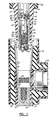
- the component parts depicted are similar to corresponding component parts illustrated and described in the aforementioned patent no. 4,202,591, in that the component parts include an electrical connector in the form of a T-shaped receptacle 10, and a terminal 12 of an electrical apparatus (not shown).
- the receptacle 10 is affixed to the terminus of a high voltage cable, in the manner illustrated in the aforesaid patent, and an electrical terminal contact 20 having an integral lug 22 is attached to the conductor of the cable. Lug 22 is to be connected to the terminal 12 to complete a distribution circuit.
- a composite body 24 surrounds the contact 20 and provides an axially extending receptacle recess 26 within which terminal 12 is to be received.
- a second axially extending recess 28, opposite to first recess 26, is to receive interface bushing assembly 30 which is constructed to enable direct connection between the terminal 12 and a commonly available electrical connector, such as an elbow receptacle (not shown).
- Bushing assembly 30 includes a generally tubular housing 34 having a body member 36 of dielectric material, such as an insulating elastomer, and a central tubular member 38 of conductive material, such as copper or aluminum.
- the upper end of the bushing assembly 30 is not illustrated, but is essentially the same as that shown in the aforesaid patent. Suffice it to say that a female contact assembly is located adjacent the upper end of the tubular member 38 and includes a female contact element which can receive a complementary male contact element for completing an electrical circuit to tubular member 38.
- tubular member 38 is provided with an extension in the form of an axially extending tubular extension member 40 of conductive material, such as copper or aluminum, affixed to tubular member 38 by means of a threaded connection 42 at the upper end 44 of tubular extension member 40.
- the lower end 46 of tubular extension member 40 includes a land 48 for the purposes which will be described in greater detail below.
- a coupling member 50 also constructed of conductive material such as copper or aluminum, is received within extension member 40, adjacent lower end 46, and is coupled to extension member 40 by means of an external thread 52 which extends axially to upper end 54 of coupling member 50 and engages a complementary internal thread 56 in extension member 40.
- a further external thread 58 extends along the coupling member 50 adjacent the lower end 60 thereof, and stop means in the form of a collar 62 is located axially between the external threads 52 and 58.
- coupling member 50 projects beyond the lower end 46 .of extension member 40, and the lower end 64 of body member 36 of bushing assembly 30, with collar 62 spaced axially from lower ends 46 and 64, as illustrated in Fig. 1.
- external thread 58 is spaced far enough downwardly from the tapered portion 66 of the body member 36 of bushing assembly 30 to enable external thread 58 to be engaged with a complementary threaded aperture 68 in lug 22 of contact 20, as seen in Fig. 2, without resistance which might otherwise occur if the tapered portion 66 of the body member 36 were to contact the corresponding tapered portion 70 of recess 28.
- external thread 58 of coupling member 50 may be threaded into threaded aperture 68 merely by turning bushing assembly 30 manually to advance external thread 58 into threaded aperture 68. Such advancement is continued until a sufficient axial length of external thread 58 is engaged within threaded aperture 68 to provide the holding strength necessary to complete the installation of the bushing assembly 30 within the receptacle 10, as described below, and preferably until a stop shoulder 72 on collar 62 is seated against lug 22, as seen in Fig. 3.
- bushing assembly 30 will advance the coupling member 50 into threaded aperture 68 until stop shoulder 72 is seated properly against lug 22.
- a locking means is provided between the external thread 52 and the internal thread 56 to lock the coupling member 50 and the tubular extension member 40 against movement relative to one another during threading of the coupling member 50 into the lug 22, at least until the aforesaid sufficient axial length of thread 58 is engaged within threaded aperture 68.
- the locking means is in the form of a pellet 74 of synthetic resin material, such as nylon, placed within a recess 76 in the wall 78 of coupling member 50 and compressed against internal thread 56 of tubular extension member 40 to establish a prevailing torque great enough to preclude the unwanted relative movement, preferably until stop shoulder 72 is seated against lug 22.
- the prevailing torque provided by pellet 74 is overcome so that downward movement of the tapered body portion 66 into complementary tapered portion 70 of recess 28 can be continued.
- the pellet 74 provides a locking means which is responsive to a minimum torque, the minimum torque being of a predetermined value which will assure that the coupling member 50 is sufficiently engaged with lug 22, and preferably is engaged up to the position where stop shoulder 72 is seated against the lug 22, before tubular extension member 40 will move relative to coupling member 50.
- Pellet 74 assures that the minimum torque necessary to engage coupling member 50 sufficiently in lug 22 and preferably to seat coupling member 50 properly against lug 22 will be reached before extension member 40 moves relative to coupling member 50.
- the attachment arrangement of the present invention further provides an internal wrenching means for facilitating the continued rotation of the bushing assembly 30, as follows.
- coupling member 50 has a central bore 80 passing through the coupling member 50 from end 54 to end 60.
- a threaded fastener in the form of a bolt 82 extends axially within the bore 80 and has a head 84 and a thread 86.
- a pin 90 extends radially through an aperture 92 in the wall of tubular member 38 and into a corresponding hole 94 in the head 84 of bolt 82, the pin 90 having a flanged end 96 which serves to locate the pin 90 radially within aperture 92.
- Tubular extension member 40 overlaps the aperture 92 thereby capturing flanged end 96 of pin 90 within aperture 92.
- Bolt 82 thus is fixed in the retracted position illustrated in Figs. 3 and 4.
- a socket 98 in head 84 of bolt 82 provides a hexagonal wrenching configuration located along the central axis A of the bushing assembly 30.
- a tool 100 having a complementary hexagonal driving element 102 is lowered through the tubular member 38, along axis A, as seen in Fig. 3, and is inserted into socket 98, as seen in Fig. 4.
- the details of tool 100 are more fully disclosed in EP-A-0092615.
- rotation of tool 100 about axis A once the tool 100 is coupled with the head 84 of bolt 82, will impart concomitant rotation to bushing assembly 30 by virtue of the fact that head 84 is secured to tubular member 38 by pin 90.
- the bushing assembly 30 It is important that the bushing assembly 30 not be overtightened; that is, the land 48 must not foul the lug 22 and excessive forces should not be developed along the interface between the complementary tapered portions 66 and 70. At the same time, it is important that at least a minimum torque is applied sufficient to assure proper seating of bushing assembly 30 within receptacle 10. In order to preclude the application of excessive wrenching forces upon the bushing assembly 30, while assuring that the necessary minimum wrenching forces are applied, the shear strength of pin 90 is chosen so that pin 90 will shear in response to the application by tool 100 of a torque in excess of a given value determined by the minimum torque required for the appropriate seating of bushing assembly 30 within receptacle 10 and the maximum torque which can be tolerated.
- pin 90 serves as a further minimum torque responsive means which includes securing means for securing the head 84 of bolt 82 to tubular member 38 for applying wrenching torque, and the securing means releases in response to exceeding a given torque to preclude the application of an excessive torque to the connection between the bushing assembly 30 and the lug 22 while assuring that the necessary minimum torque is applied.
- bolt 82 is free to move axially downwardly within tubular extension member 40 and coupling member 50, until the head 84 of bolt 82 rests upon washers 105 located at the upper end 54 of coupling member 50. It is noted that axially upward movement of bolt 82 is restricted by a lip 106 which projects radially inwardly to preclude movement of bolt 82 upwardly into tubular member 38 beyond lip 106.
- the bolt 82 may be advanced and threaded into the terminal 12, by rotation of tool 100, to complete the connection to the terminal 12, as shown in Fig. 5.
- bolt 82 clamps lug 22 in place upon the terminal 12 and secures receptacle 10 upon terminal 12 with the appropriate interference fit at the interface between the recess 26 of the receptacle 10 and the corresponding outer surface 110 of the terminal 12 and the proper electrical contact between the lug 22 and the conductor 111 of terminal 12.
- stop shoulder 72 of collar 62 is seated against lug 22 to preclude the projection of end 60 of coupling member 50 downwardly beyond lug 22 so as to assure proper contact between lug 22 and conductor 111 of terminal 12.
- Fragment 112 of sheared pin 90 is retained within aperture 92 in the wall of tubular member 38 by virtue of flanged end 96 so as to prevent the fragment from dropping freely into the bushing assembly 30 and possibly causing problems, such as falling into socket 98 and interfering with the appropriate engagement of hexagonal element 102 of tool 100.
- fragment 114 of sheared pin 90 is confined within hole 94 of bolt head 84, by the wall of tubular extension member 40. Thus, the location of fragments 112 and 114 is controlled. Tool 100 then is withdrawn, as shown.
- the attachment arrangement of the present invention facilitates the appropriate installation of the bushing assembly 30 within the receptacle 10 and then enables connection of the receptacle 10 to the terminal 12 in simplified operations performed readily in the field without complex tools.
Landscapes
- Connector Housings Or Holding Contact Members (AREA)
- Details Of Connecting Devices For Male And Female Coupling (AREA)
Claims (8)
Priority Applications (5)
| Application Number | Priority Date | Filing Date | Title |
|---|---|---|---|
| EP19820302064 EP0092616B1 (fr) | 1982-04-22 | 1982-04-22 | Dispositif de fixation pour connecteur électrique haute tension |
| DE8282302064T DE3272107D1 (en) | 1982-04-22 | 1982-04-22 | Attachment arrangement for high voltage electrical connector |
| DE1982302064 DE92616T1 (de) | 1982-04-22 | 1982-04-22 | Befestigungsanordnung fuer elektrischen hochspannungsverbinder. |
| SG83886A SG83886G (en) | 1982-04-22 | 1986-10-18 | Attachment arrangement for high voltage electrical connector |
| HK15587A HK15587A (en) | 1982-04-22 | 1987-02-19 | Attachment arrangement for high voltage electrical connector |
Applications Claiming Priority (1)
| Application Number | Priority Date | Filing Date | Title |
|---|---|---|---|
| EP19820302064 EP0092616B1 (fr) | 1982-04-22 | 1982-04-22 | Dispositif de fixation pour connecteur électrique haute tension |
Publications (2)
| Publication Number | Publication Date |
|---|---|
| EP0092616A1 EP0092616A1 (fr) | 1983-11-02 |
| EP0092616B1 true EP0092616B1 (fr) | 1986-07-23 |
Family
ID=8189646
Family Applications (1)
| Application Number | Title | Priority Date | Filing Date |
|---|---|---|---|
| EP19820302064 Expired EP0092616B1 (fr) | 1982-04-22 | 1982-04-22 | Dispositif de fixation pour connecteur électrique haute tension |
Country Status (4)
| Country | Link |
|---|---|
| EP (1) | EP0092616B1 (fr) |
| DE (2) | DE92616T1 (fr) |
| HK (1) | HK15587A (fr) |
| SG (1) | SG83886G (fr) |
Families Citing this family (3)
| Publication number | Priority date | Publication date | Assignee | Title |
|---|---|---|---|---|
| EP0147979B1 (fr) * | 1983-12-14 | 1990-05-23 | Raychem Limited | Connecteur haute tension |
| GB8906886D0 (en) * | 1989-03-28 | 1989-05-10 | Raychem Ltd | Electrical connector |
| DE102007027223A1 (de) * | 2007-06-13 | 2008-12-24 | Mahle International Gmbh | Kolbenring für den Kolben eines Verbrennungsmotors |
Family Cites Families (3)
| Publication number | Priority date | Publication date | Assignee | Title |
|---|---|---|---|---|
| US3191486A (en) * | 1962-10-29 | 1965-06-29 | Martin Marietta Corp | Automatic torque indicating and applying devices |
| US3959869A (en) * | 1974-03-29 | 1976-06-01 | Amerace Corporation | Apparatus for the remote grounding, connection and disconnection of high voltage electrical circuits |
| US4202591A (en) * | 1978-10-10 | 1980-05-13 | Amerace Corporation | Apparatus for the remote grounding, connection and disconnection of high voltage electrical circuits |
-
1982
- 1982-04-22 DE DE1982302064 patent/DE92616T1/de active Pending
- 1982-04-22 DE DE8282302064T patent/DE3272107D1/de not_active Expired
- 1982-04-22 EP EP19820302064 patent/EP0092616B1/fr not_active Expired
-
1986
- 1986-10-18 SG SG83886A patent/SG83886G/en unknown
-
1987
- 1987-02-19 HK HK15587A patent/HK15587A/xx unknown
Also Published As
| Publication number | Publication date |
|---|---|
| EP0092616A1 (fr) | 1983-11-02 |
| DE92616T1 (de) | 1984-05-10 |
| SG83886G (en) | 1987-07-03 |
| HK15587A (en) | 1987-02-27 |
| DE3272107D1 (en) | 1986-08-28 |
Similar Documents
| Publication | Publication Date | Title |
|---|---|---|
| US4354721A (en) | Attachment arrangement for high voltage electrical connector | |
| US4360967A (en) | Assembly tool for electrical connectors | |
| EP0649189B1 (fr) | Assemblage de connecteur électrique et son procédé de connexion | |
| CA2056226C (fr) | Connecteur a haute tension coude | |
| US4202591A (en) | Apparatus for the remote grounding, connection and disconnection of high voltage electrical circuits | |
| US6802738B1 (en) | Connector for coaxial cable with multiple start threads | |
| EP3021424B1 (fr) | Ensemble de connecteur électrique comprenant une liaison de mise à la terre et procédé correspondant de connexion | |
| US3798586A (en) | Union for connecting electrical conductors | |
| US5421750A (en) | 200 AMP bolted elbow with a loadbreak tap | |
| US4382651A (en) | Transformer bar connector | |
| US4545633A (en) | Weatherproof positive lock connector | |
| US4779341A (en) | Method of using a tap plug installation tool | |
| EP2688153A2 (fr) | Connecteur électrique comportant un mécanisme de mise à la terre | |
| US4715104A (en) | Installation tool | |
| JPS63148576A (ja) | 高圧電気コネクタ | |
| CN102388505A (zh) | 具有双夹紧螺母的同轴连接器 | |
| US3959869A (en) | Apparatus for the remote grounding, connection and disconnection of high voltage electrical circuits | |
| US4776089A (en) | Method of assembling tap plug to cable connector | |
| EP0092616B1 (fr) | Dispositif de fixation pour connecteur électrique haute tension | |
| CA1177129A (fr) | Fixation pour connecteur haute tension | |
| JPS6355752B2 (fr) | ||
| EP0092615B1 (fr) | Outil d'assemblage pour connecteurs électriques | |
| CA1179488A (fr) | Outil pour assembler des connecteurs electriques | |
| JPH0145718B2 (fr) | ||
| US12347966B2 (en) | Deadbreak connector |
Legal Events
| Date | Code | Title | Description |
|---|---|---|---|
| PUAI | Public reference made under article 153(3) epc to a published international application that has entered the european phase |
Free format text: ORIGINAL CODE: 0009012 |
|
| AK | Designated contracting states |
Designated state(s): BE DE FR GB IT NL SE |
|
| ITCL | It: translation for ep claims filed |
Representative=s name: SOCIETA' ITALIANA BREVETTI S.P.A. |
|
| TCNL | Nl: translation of patent claims filed | ||
| EL | Fr: translation of claims filed | ||
| DET | De: translation of patent claims | ||
| 17P | Request for examination filed |
Effective date: 19840409 |
|
| GRAA | (expected) grant |
Free format text: ORIGINAL CODE: 0009210 |
|
| ITF | It: translation for a ep patent filed | ||
| AK | Designated contracting states |
Kind code of ref document: B1 Designated state(s): BE DE FR GB IT NL SE |
|
| REF | Corresponds to: |
Ref document number: 3272107 Country of ref document: DE Date of ref document: 19860828 |
|
| ET | Fr: translation filed | ||
| PGFP | Annual fee paid to national office [announced via postgrant information from national office to epo] |
Ref country code: NL Payment date: 19870430 Year of fee payment: 6 |
|
| PLBE | No opposition filed within time limit |
Free format text: ORIGINAL CODE: 0009261 |
|
| STAA | Information on the status of an ep patent application or granted ep patent |
Free format text: STATUS: NO OPPOSITION FILED WITHIN TIME LIMIT |
|
| 26N | No opposition filed | ||
| PG25 | Lapsed in a contracting state [announced via postgrant information from national office to epo] |
Ref country code: SE Effective date: 19890423 |
|
| PG25 | Lapsed in a contracting state [announced via postgrant information from national office to epo] |
Ref country code: BE Effective date: 19890430 |
|
| PGFP | Annual fee paid to national office [announced via postgrant information from national office to epo] |
Ref country code: GB Payment date: 19890430 Year of fee payment: 8 |
|
| BERE | Be: lapsed |
Owner name: AMERACE CORP. Effective date: 19890430 |
|
| PG25 | Lapsed in a contracting state [announced via postgrant information from national office to epo] |
Ref country code: NL Effective date: 19891101 |
|
| NLV4 | Nl: lapsed or anulled due to non-payment of the annual fee | ||
| PG25 | Lapsed in a contracting state [announced via postgrant information from national office to epo] |
Ref country code: FR Free format text: LAPSE BECAUSE OF NON-PAYMENT OF DUE FEES Effective date: 19891228 |
|
| PG25 | Lapsed in a contracting state [announced via postgrant information from national office to epo] |
Ref country code: DE Effective date: 19900103 |
|
| REG | Reference to a national code |
Ref country code: FR Ref legal event code: ST |
|
| PG25 | Lapsed in a contracting state [announced via postgrant information from national office to epo] |
Ref country code: GB Effective date: 19900422 |
|
| GBPC | Gb: european patent ceased through non-payment of renewal fee | ||
| EUG | Se: european patent has lapsed |
Ref document number: 82302064.9 Effective date: 19900412 |