EP0092691A2 - Vorrichtung zur Ermittlung eines Sicherheitsfadens eingebettet in einem papierähnlichen Material - Google Patents
Vorrichtung zur Ermittlung eines Sicherheitsfadens eingebettet in einem papierähnlichen Material Download PDFInfo
- Publication number
- EP0092691A2 EP0092691A2 EP83103206A EP83103206A EP0092691A2 EP 0092691 A2 EP0092691 A2 EP 0092691A2 EP 83103206 A EP83103206 A EP 83103206A EP 83103206 A EP83103206 A EP 83103206A EP 0092691 A2 EP0092691 A2 EP 0092691A2
- Authority
- EP
- European Patent Office
- Prior art keywords
- security thread
- paper
- signal
- detection
- reference voltage
- Prior art date
- Legal status (The legal status is an assumption and is not a legal conclusion. Google has not performed a legal analysis and makes no representation as to the accuracy of the status listed.)
- Granted
Links
Images
Classifications
-
- G—PHYSICS
- G07—CHECKING-DEVICES
- G07D—HANDLING OF COINS OR VALUABLE PAPERS, e.g. TESTING, SORTING BY DENOMINATIONS, COUNTING, DISPENSING, CHANGING OR DEPOSITING
- G07D7/00—Testing specially adapted to determine the identity or genuineness of valuable papers or for segregating those which are unacceptable, e.g. banknotes that are alien to a currency
- G07D7/06—Testing specially adapted to determine the identity or genuineness of valuable papers or for segregating those which are unacceptable, e.g. banknotes that are alien to a currency using wave or particle radiation
- G07D7/12—Visible light, infrared or ultraviolet radiation
Definitions
- This invention relates to an apparatus for detecting a security thread which is embedded in paper-like materials such as paper currencies, checks or securities for the purpose of preventing forgerise.
- a security thread which may be an elongaged nonmetal piece (e.g., a plastic piece) or an elongated metal piece (e.g., an aluminum piece), is embedded in a paper currency.
- the security thread is effective in preventing forgery since the paper currency can be identified by the presence and quality of the security thread.
- accurate detection of the security thread is hard to achieve. Since a sensor must be kept in close contact with the paper currency to detect the thread by a change in the thickness of the paper money, some creases or folds will inevitably be detected as a security thread. Nor has any apparatus been proposed to distinguish a plastic security thread from an aluminum security thread, and vice versa.
- an apparatus for optically detecting a security thread embedded in a paper-like material which comprises a radiation source for radiating infrared rays to the paper-like material; first detection means having a first filter adapted to receive the infrared rays passing through the paper-like material and to generate a first electrical signal corresponding to the amount of infrared radiation incident on the first filter; second detection means having a second filter with infrared radiation transmission characteristics different from the first filter, adapted to receive the infrared rays passing through the paper-like material and to generate a second electrical signal corresponding to the amount of infrared radiation incident on the second filter; and discrimination means connected to the first and second detection means for detecting variations of the first and second electrical signals to thereby de.termine whether a security thread is present in the paper-like material and what the security thread is made of.
- a paper-like material e.g., a paper currency (money) with a security thread embedded therein is placed between an infrared radiation source on one hand and two infrared radiation detectors on the other.
- Two optical filters are mounted on these detectors. They have different infrared ray transmission characteristics. More precisely, one detector is sensitive only to the infrared rays whose wavelengths fall within a specific range, which is determined by one optical filter, and another detector is sensitive only to the infrared rays whose wavelengths fall with a different range from the former, which is determined by another optical filter.
- the infrared radiation source projects infrared rays to the paper-like material.
- Both detectors receive via the respective optical filter the infrared radiation which has passed through the paper-like material and whose wavelengths fall within the specific ranges and produce electrical signals whose levels correspond to the amounts of the received infrared rays.
- the paper-like material is moved in the direction perpendicular to the infrared radiations direction.
- the detected signal levels become lower than that in no security thread. The security thread is thus detected.
- the signal levels of the two detectors are compared with each other so as to discriminate whether the detected security thread is made of metallic or nonmetallic material.
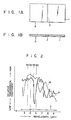
- Figs. 1A and lB show a paper money P consisting of a sheet of paper 1 and a security thread 2 embedded in the sheet 1.
- the security thread 2 is made of plastic, e.g., polyethylene terephthalate, or aluminum. It is about 20 microns thick, about 0.5 to 1.0 mm and as long as the sheet 1 is wide.
- the thread 2 extends in the widthwise direction of the paper money P, which is carried along its longitudinal direction.
- Fig. 2 illustrates the infrared ray transmission characteristics of the sheet 1, a plastic security thread and an aluminum security thread. More specifically, curve A indicates the transmission characteristic coefficient of the typical plastic security thread relative to the warelength of infrared rays, curve B represents that of the paper currency relative to the wavelength of infrared rays, and line C shows that of the aluminum security thread relative to the wavelength of infrared rays.
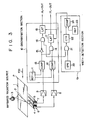
- Fig. 3 shows an apparatus according to the invention.
- the paper money P is carried by a conveyor belt (not shown) in the direction of an arrow 100 (longitudinal direction of the paper money), while being held tautly by a pair of members (not shown) which clamp the both ends of the paper money P.
- a security thread 2 which is embedded in the paper currency P and extends widthwise within the paper currency P is therefore at right angles to the carrying direction.
- An infrared radiation source 3 e.g., an SiC light emitting element
- Two infrared band-pass filters 4 and 5 are positioned below the conveyor belt and arranged side by side along the conveyor belt, to thereby receive infrared rays transmitting from the infrared radiation source 3 through the paper currency P.
- One filter 4 passes only infrared rays which have wavelengths of 5.5 to 6.0 microns and which are well absorbed by plastics.
- the other filter 5 passes only infrared rays which have wavelengths of 4.5 to 5.0 microns and which are scarcely absorbed by paper as well as plastics.
- the filters 4 and 5 are designed to have very different filtering characteristics. Both filters 4 and 5 are elongated rectangular shapes.
- Two infrared radiation detecting elements 6 and 7 (e.g., InSb elements), which are also rectangular plates, are attached to the lower faces of the filters 4 and 5, respectively.
- the elements 6 and 7 detect infrared rays passing through the filters 4 and 5 and convert these rays into electrical signals.
- the filters 4 and 5 and the elements 6 and 7 extend at right angles to the conveyor belt (not shown) and are as long as the security thread 2. If they are too long, the detection signals from the elements 6 and 7 may have a poor S/N ratio.
- the electrical signal from the first detector element 6 is amplified by a amplifier 8 and then supplied to a discrimination section 10.
- the signal from the second detector element 7 is also amplified by a amplifier 9 and then supplied to the discrimination section 10.
- the discrimination section 10 is designed to determine whether or not a security thread 2 is embedded in the paper currency P and whether the security thread 2 is made of metallic or nonmetallic material.
- the section 10 comprises a reference voltage generator 11 (e.g., a DC power source) for delivering a first and second reference voltages, a first analog comparator 12 for comparing the signal from the amplifier 8 with the first reference voltage from the generator 11, a second analog comparator 13 for comparing the signal from the amplifier 9 with the second reference voltage from the generator 11, an AND circuit 14 for obtaining the logical product of output signals from the two comparators 12 and 13, an inverter circuit 15 for inverting the output signal from the second comparator 13, an AND circuit 16 for obtaining the logical product of output signals from the first comparator 12 and inverter circuit 15, and a first and second latch circuits 17 and 18 for latching output signals from the AND circuits 14 and 15, respectively.
- the latch circuits 17 and 18 deliver their contents in response to a truth signal supplied from a width detection section 19 which will be described later.
- the first reference voltage is usually different from the second reference voltage, but the former is equal to the latter in the specific case.
- the section 19 is designed to detect the width of a security thread. When the width of the security thread is determined to be equal to the standard one, the width detection section 19 produces and supplies a truth signal simultaneously to the latch circuits 17 and 18.
- the section 19 comprises a sampling pulse generator 20, an AND circuit 21 for obtaining the logical product of a sampling pulse from the generator 20 and the output signal from the first comparator 12, a counter 22 for counting output signals from the AND circuit 21, a reference value generator 23 for delivering the digital reference value corresponding to the standard one, and a digital comparator 24 for comparing counts of the counter 22 with the reference value originated from the reference value generator 23.
- any portion of the paper currency P in which no security thread is embedded lies in the projection area defined by the infrared radiation source 3 on one hand and the infrared radiation detectors 6 and 7 on the other. Since the paper currency P has a relatively high transmission coefficient for infrared rays having wavelengths of 4.5 to 5.0 microns and 5.5 to 6.0 microns, as indicated by curve B in Fig. 2, both detectors 6 and 7 may derive high-level electrical signals respectively. These detected signals are supplied to the first and second comparators 12 and 13 after amplified in the amplifiers 8 and 9, respectively. The first comparator 12 compares the detected signal from the ditector 6 with the first reference voltage from the reference voltage generator 11.
- the second comparator 13 compares the detected signal from the detector 7 with the second reference voltage.
- the first comparator 12 outputs a logic "0" signal when the detected signal has a level higher than the first reference voltage and a logic "1" signal when the detected signal has a level lower than the first reference voltage.
- the second comparator 13 outputs a logic "1” signal when the detected signal has a level higher than the second reference voltage and a logic "0" signal when the signal has a level lower than the second reference voltage.
- the first and second comparators 12 and 13 are designed in such a manner that the comparison outputs have different logic levels each other with respect to the same input signal level to the comparators.
- the comparators 12 and 13 Since the output signals from both detectors 6 and 7 have a high level in the above-mentioned case, the comparators 12 and 13 outputs a logic "1" signal and a logic "0" signal, respectively. Hence, neither the AND circuit 14 nor the AND circuit 16 produces an output signal.
- the latch circuits 17 and 18 have no latching signal and thus output logic "0" signals. In this case, the discrimination section 10 determines that no security thread is embedded in that portion of the paper currency P which lies between the infrared radiation source 3 on the one hand and the detectors 6 and 7 on the other hand.
- both detectors 6 and 7 produce low-level electrical signals since the infrared rays from the infrared radiation source 3 can hardly pass through the aluminum security thread 2 as indicated by line C in Fig. 2.
- the comparators 12 and 13 output a logic "1" signal and a logic "0" signal, respectively. Therefore, only the AND circuit 16 produces a logic "1” signal. Then the second latch circuit 18 latches this logic "1" signal and delivers this signal as an indication of the aluminum thread signal AL-OUT when the width detection section 19 produces the truth signal.
- the discrimination section 10 compares the output signals from the infrared radiation detectors 6 and 7 with a predetermined reference value, i.e., a DC reference voltage. Depending on whether the levels of these signals are higher or lower than the relevant DC reference voltage, the discrimination section 10 determines whether or not a security thread lies in the projection (detection) region, and moreover whether a security thread, if detected, is made of plastic or aluminum.
- a predetermined reference value i.e., a DC reference voltage
- the security thread 2 is a long, thin strip which is embedded in the paper currency P and extends in the widthwise direction of the paper currency P.
- the width detection section 19 may detect the width - of the thread 2 to determine whether or not the paper currency P is genuine, thus more effectively preventing forgery.
- the width detection section 19 The operation of the width detection section 19 will now be described.
- the portion of a paper currency P in which a security thread 2 made of plastic or aluminum is embedded lies in the detection region defined by the infrared radiation source 3 on the one hand and the detectors 6 and 7 on the other.
- the output signal from the first amplifier 8 therefore has a low level.
- the first comparator 12 then outputs a logic "1" signal.
- the AND circuit 21 obtains the logical product of the logic "1" signal from the comparator 12 and the sampling pulse from the sampling pulse generator 20 and therefore produces an output . signal.
- the output signal from the AND circuit 21 is supplied to the counter 22.
- the AND circuit 21 samples the comparison signal from the first comparator 12 with the sampling pulse when the comparison signal becomes logic "1" level and supplies a sampling output signal to the counter 22.
- the counter 22 counts output signals from the AND circuit 21, i.e., sampling output signal pulses, and supplies a signal representing the count to a third digital comparator 24.
- the third comparator 24 compares the count of the counter 22 with the reference value supplied from the reference value generator 23 and having the digital value corresponding to the standard width of the security thread 2. If the count of the counter 22 is equal to the reference value, the digital comparator 24 produces a logic "1" signal, i.e., a truth signal.
- the comparison output in the period during which the level of the output signal from the amplifier 8 is low i.e., the period during which the detector 6 detects the security thread 2
- the number of sampling pulses from the AND circuit 21 is proportional to the width of the security thread 2.
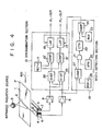
- the apparatus of Fig. 4 comprises mainly a discrimination section 10 as well as a width detection section 19.
- the discrimination section 10 comprises a difference detection circuit 25 for detecting the difference between the output signals from amplifiers 8 and 9, and a summation detection circuit 26 for detecting the sum of the output signals from the amplifiers 8 and 9.
- This section 10 further comprises first and second analog comparators 12' and 13' and the first and second latch circuits 17 and 18.
- the first analog comparator 12' is designed to compare the level of the output signal from the difference detection circuit 25 with a first reference voltage from a first reference voltage generator 11 and to produce a logic "1" signal when the output signal from the circuit 25 has a level higher than the first reference voltage, and a logic "0" signal when the signal has a level lower than the first reference voltage.
- the second analog comparator 13' is designed to compare the level of the output signal from the summation detection circuit 26 with a second reference voltage from a reference voltage generator 11 and to produce a logic "1” signal when the signal has a level lower than the second reference voltage, and a logic "0” signal when the signal has a level higher than the second reference voltage. It should be noted that the first reference voltage is usually different from the second reference voltage, but.
- the first latch circuit 17 is designed to latch an output signal from the first comparator 12', and the second latch circuit 18 to latch an output signal from the second comparator 13'.
- the width detection section 19 comprises a third analog comparator 27, a second reference voltage generator 28, a sampling pulse generator 20, an A!!D circuit 21, a counter 22, a reference value generator 23 and a digital comparator 24.
- the third analog comparator 27 is designed to compare a level of an output signal from the amplifier 8 with a third reference voltage from the second reference voltage generator 28 and to produce a logic "1" signal when the signal has a level lower than the third reference voltage, and a logic "0" signal when the signal has a level equal to or higher than the third reference voltage.
- the AND circuit 21 is designed to obtain the logical product of an output signal from the third comparator 27 and a sampling pulse from the sampling pulse generator 20.
- any portion of a paper currency P in which no security thread is embedded lies in the detection region defined by an infrared radiation source 3 and infrared radiation detectors 6 and 7. Both detectors 6 and 7 output high-level electrical signals.
- the difference detection circuit 25 therefore outputs a low-level signal, whereas the summation detection circuit 26 outputs a high-level signal as a result of the calculation.
- Both analog comparators 12' and 13' then produce logic "0" signals.
- Neither the first latch circuit 17 nor the second latch circuit 18 latches any output signal from the comparators 12' and 13'.
- both the difference between the output signals from the detectors 6 and 7, and the sum of these output signals are calculated, and the difference and sum thus calculated are compared with predetermined relative reference values, thereby easily detecting the presence of a security thread 2 in a paper currency P and easily discriminating whether the thread 2 is made of plastic or aluminum.
- the comparators 12' and 13' are completely identical to the comparators 12 and 13, but only difference is how to operate them in each embodiment, and in both embodiments described above the reference voltage generator 11 can be comprised of, for example, a series circuit of a resistor and a Zener diode connected to a DC source and a variable resistor connected in parallel to the Zener diode.
- the reference voltage is supplied from the sliding terminal of the variable resistor.
- the apparatus according to the invention is advantageous in the following respects. First, it can reliably detect a security thread in a paper currency even if the paper currency has wrinkles and/or folds, since the detectors are spaced apart from the paper currency. Second, it can discriminate whether or not a security thread, when detected, is made of metallic or nonmetallic material.
- the infrared band-pass-filters and infrared radiation detectors are not limited to rectangular ones, they may also be square. Further, more than two filters and more than two detectors may be arranged side by side in the widthwise direction of a security thread embedded in a paper currency and the electrical signals from the three or more detectors may be processed to achieve the same effects as in the embodiments described above.
- the apparatus according to the invention can detect not only security threads embedded in paper currencies but also those embedded in checks or securities.
Landscapes
- Health & Medical Sciences (AREA)
- General Health & Medical Sciences (AREA)
- Toxicology (AREA)
- Physics & Mathematics (AREA)
- General Physics & Mathematics (AREA)
- Inspection Of Paper Currency And Valuable Securities (AREA)
- Yarns And Mechanical Finishing Of Yarns Or Ropes (AREA)
- Paper (AREA)
- Credit Cards Or The Like (AREA)
- Image Processing (AREA)
- Image Analysis (AREA)
Priority Applications (1)
| Application Number | Priority Date | Filing Date | Title |
|---|---|---|---|
| AT83103206T ATE49074T1 (de) | 1982-04-06 | 1983-03-30 | Vorrichtung zur ermittlung eines sicherheitsfadens eingebettet in einem papieraehnlichen material. |
Applications Claiming Priority (2)
| Application Number | Priority Date | Filing Date | Title |
|---|---|---|---|
| JP57055993A JPS58175091A (ja) | 1982-04-06 | 1982-04-06 | セキユリテイ・ストレツド検出装置 |
| JP55993/82 | 1982-04-06 |
Publications (4)
| Publication Number | Publication Date |
|---|---|
| EP0092691A2 true EP0092691A2 (de) | 1983-11-02 |
| EP0092691A3 EP0092691A3 (en) | 1986-10-08 |
| EP0092691B1 EP0092691B1 (de) | 1989-12-27 |
| EP0092691B2 EP0092691B2 (de) | 1994-04-27 |
Family
ID=13014601
Family Applications (1)
| Application Number | Title | Priority Date | Filing Date |
|---|---|---|---|
| EP83103206A Expired - Lifetime EP0092691B2 (de) | 1982-04-06 | 1983-03-30 | Vorrichtung zur Ermittlung eines Sicherheitsfadens eingebettet in einem papierähnlichen Material |
Country Status (5)
| Country | Link |
|---|---|
| US (1) | US4524276A (de) |
| EP (1) | EP0092691B2 (de) |
| JP (1) | JPS58175091A (de) |
| AT (1) | ATE49074T1 (de) |
| DE (1) | DE3381026D1 (de) |
Cited By (24)
| Publication number | Priority date | Publication date | Assignee | Title |
|---|---|---|---|---|
| EP0185396A3 (en) * | 1984-12-21 | 1987-05-27 | Gao Gesellschaft Fur Automation Und Organisation Mbh | Security document incorporating a security thread, and process for manufacturing and checking the authenticity of the security document |
| FR2600191A1 (fr) * | 1986-06-17 | 1987-12-18 | Laurel Bank Machine Co | Discriminateur de papier-monnaie |
| EP0315611A3 (en) * | 1987-11-06 | 1990-03-07 | Lance May | Method and arrangement for validating coupons |
| WO1991008556A1 (en) * | 1989-11-24 | 1991-06-13 | Price Stern Sloan, Inc. | Security print detectors |
| WO1992014221A1 (de) * | 1991-02-08 | 1992-08-20 | De La Rue Giori S.A. | Prüfanordnung |
| US5279403A (en) * | 1992-07-23 | 1994-01-18 | Crane & Company, Inc. | Microwave security thread detector |
| GB2299665A (en) * | 1995-04-07 | 1996-10-09 | David Frank Maratos | Bank note verification device |
| EP0744720A1 (de) * | 1995-05-24 | 1996-11-27 | N.V. Bekaert S.A. | Echtheitsprüfung von Sicherheitsdokumenten |
| AT401829B (de) * | 1992-02-25 | 1996-12-27 | Oesterr Nationalbank | Verfahren zur zustands-, qualitäts- bzw. passerkontrolle von optischen sicherheitsmerkmalenauf wertpapieren, insbesondere banknoten, und vorrichtung zur durchführung des verfahrens |
| US5672859A (en) * | 1994-03-04 | 1997-09-30 | N.V. Bekaert S.A. | Reproduction apparatus with microwave detection |
| WO1998049657A2 (de) | 1997-04-25 | 1998-11-05 | WHD elektronische Prüftechnik GmbH | Aufbau von sicherheitselementen für dokumente und vorrichtungen zur prüfung von dokumenten mit derartigen sicherheitselementen sowie verfahren zur anwendung |
| WO1999009528A1 (de) | 1997-08-12 | 1999-02-25 | WHD elektronische Prüftechnik GmbH | Aufbau von sicherheitselementen für dokumente und vorrichtungen zur prüfung von dokumenten mit derartigen sicherheitselementen sowie verfahren zur anwendung dieser sicherheitselemente und vorrichtungen |
| ES2184646A1 (es) * | 2001-09-21 | 2003-04-01 | Fab Nac Moneda Y Timbre Es | Metodo de analisis de la nubosidad visual del papel de seguridad, y dispositivo para la puesta en practica del mismo. |
| WO2007028640A1 (de) * | 2005-09-09 | 2007-03-15 | Giesecke & Devrient Gmbh | Verfahren und vorrichung zum testen von wertdokumenten |
| CN105339180A (zh) * | 2013-03-15 | 2016-02-17 | 光学物理有限责任公司 | 光学安全性设备 |
| US9873281B2 (en) | 2013-06-13 | 2018-01-23 | Visual Physics, Llc | Single layer image projection film |
| US10173405B2 (en) | 2012-08-17 | 2019-01-08 | Visual Physics, Llc | Process for transferring microstructures to a final substrate |
| US10189292B2 (en) | 2015-02-11 | 2019-01-29 | Crane & Co., Inc. | Method for the surface application of a security device to a substrate |
| US10195890B2 (en) | 2014-09-16 | 2019-02-05 | Crane Security Technologies, Inc. | Secure lens layer |
| US10434812B2 (en) | 2014-03-27 | 2019-10-08 | Visual Physics, Llc | Optical device that produces flicker-like optical effects |
| US10766292B2 (en) | 2014-03-27 | 2020-09-08 | Crane & Co., Inc. | Optical device that provides flicker-like optical effects |
| US10800203B2 (en) | 2014-07-17 | 2020-10-13 | Visual Physics, Llc | Polymeric sheet material for use in making polymeric security documents such as banknotes |
| US10890692B2 (en) | 2011-08-19 | 2021-01-12 | Visual Physics, Llc | Optionally transferable optical system with a reduced thickness |
| US11590791B2 (en) | 2017-02-10 | 2023-02-28 | Crane & Co., Inc. | Machine-readable optical security device |
Families Citing this family (64)
| Publication number | Priority date | Publication date | Assignee | Title |
|---|---|---|---|---|
| CH653459A5 (de) * | 1981-04-16 | 1985-12-31 | Landis & Gyr Ag | Dokument mit einem sicherheitsfaden und verfahren zur echtheitspruefung desselben. |
| GB8311795D0 (en) * | 1983-04-29 | 1983-06-02 | De La Rue Syst | Detecting luminescent security features |
| JPH0662030B2 (ja) * | 1987-03-05 | 1994-08-17 | クレイン アンド カンパニ− | 安全紙並びにそれに使用される安全帯片及びその形成方法 |
| NL8802404A (nl) * | 1988-09-30 | 1990-04-17 | Meyn Bv | Werkwijze en inrichting voor het door middel van doorstraling controleren van voedselprodukten. |
| US4980569A (en) * | 1990-03-05 | 1990-12-25 | Crane Timothy T | Security paper verification device |
| US5151607A (en) * | 1991-05-02 | 1992-09-29 | Crane Timothy T | Currency verification device including ferrous oxide detection |
| US5394969A (en) * | 1991-12-31 | 1995-03-07 | Authentication Technologies, Inc. | Capacitance-based verification device for a security thread embedded within currency paper |
| US5308992A (en) * | 1991-12-31 | 1994-05-03 | Crane Timothy T | Currency paper and banknote verification device |
| JPH05188845A (ja) * | 1992-01-10 | 1993-07-30 | Dainippon Printing Co Ltd | ホログラム |
| US5260582A (en) * | 1992-04-20 | 1993-11-09 | Danek Robert J | Currency verification device for detecting the presence or the absence of security threads |
| CA2108823C (en) * | 1992-10-23 | 1999-09-14 | Shinobu Arimoto | Image processing apparatus and method therefor |
| GB2273353A (en) * | 1992-12-02 | 1994-06-15 | Colin Stephen Henley | Security device |
| US5417316A (en) * | 1993-03-18 | 1995-05-23 | Authentication Technologies, Inc. | Capacitive verification device for a security thread embedded within currency paper |
| US5416307A (en) * | 1993-09-03 | 1995-05-16 | Danek; Robert | Currency paper verification and denomination device |
| DE4447705C2 (de) * | 1993-10-30 | 2000-04-13 | Ricoh Kk | Bilderzeugungseinrichtung, die ein Spezialdokument identifizieren kann |
| US5399874A (en) * | 1994-01-18 | 1995-03-21 | Gonsalves; Robert A. | Currency paper verification and denomination device having a clear image and a blurred image |
| US5468971A (en) * | 1994-03-14 | 1995-11-21 | Ebstein; Steven | Verification device for currency containing an embedded security thread |
| US5419424A (en) * | 1994-04-28 | 1995-05-30 | Authentication Technologies, Inc. | Currency paper security thread verification device |
| US5680472A (en) * | 1994-06-09 | 1997-10-21 | Cr Machines, Inc. | Apparatus and method for use in an automatic determination of paper currency denominations |
| US5535871A (en) * | 1995-08-29 | 1996-07-16 | Authentication Technologies, Inc. | Detector for a security thread having at least two security detection features |
| KR100356726B1 (ko) * | 1995-11-21 | 2003-01-24 | 후지쯔 가부시끼가이샤 | 유가증서처리장치 |
| GB2309778B (en) | 1996-02-05 | 2000-05-24 | Mars Inc | Security document validation |
| DE19747095B4 (de) * | 1996-10-25 | 2007-06-06 | Ricoh Co., Ltd. | Bestimmungsvorrichtung für ein spezifisches Dokument und Bildleseapparat mit einer solchen Bestimmungseinrichtung |
| US6696696B1 (en) * | 1996-10-25 | 2004-02-24 | Ricoh Company, Ltd. | Image forming apparatus with specific document module having a microwave sensor |
| US7584883B2 (en) | 1996-11-15 | 2009-09-08 | Diebold, Incorporated | Check cashing automated banking machine |
| US5923413A (en) * | 1996-11-15 | 1999-07-13 | Interbold | Universal bank note denominator and validator |
| US6573983B1 (en) | 1996-11-15 | 2003-06-03 | Diebold, Incorporated | Apparatus and method for processing bank notes and other documents in an automated banking machine |
| US7513417B2 (en) | 1996-11-15 | 2009-04-07 | Diebold, Incorporated | Automated banking machine |
| US7559460B2 (en) | 1996-11-15 | 2009-07-14 | Diebold Incorporated | Automated banking machine |
| US6104036A (en) * | 1998-02-12 | 2000-08-15 | Global Payment Technologies | Apparatus and method for detecting a security feature in a currency note |
| US6155491A (en) * | 1998-05-29 | 2000-12-05 | Welch Allyn Data Collection, Inc. | Lottery game ticket processing apparatus |
| US6483576B1 (en) * | 1999-12-10 | 2002-11-19 | Laser Lock Technologies, Inc. | Counterfeit detection system |
| US6813011B2 (en) * | 1999-12-10 | 2004-11-02 | Laser Lock Technologies, Inc. | Process for blending of ink used in counterfeit detection systems |
| DE10227354A1 (de) * | 2002-06-19 | 2004-01-08 | Giesecke & Devrient Gmbh | Erkennung von Fremdobjekten auf oder in Banknoten |
| KR100661440B1 (ko) * | 2002-08-30 | 2006-12-27 | 후지츠 프론테크 가부시키가이샤 | 종이류 특징 검출 장치 및 종이류 특징 검출 방법 |
| JP4008843B2 (ja) * | 2002-09-19 | 2007-11-14 | 株式会社エヌ・ティ・ティ・ドコモ | 移動通信システム、移動局、基地局及び無線制御装置 |
| KR100764266B1 (ko) | 2003-06-26 | 2007-10-05 | 가부시키가이샤 파이롯트 코포레이숀 | 필기구의 축통 |
| US8867134B2 (en) | 2003-11-21 | 2014-10-21 | Visual Physics, Llc | Optical system demonstrating improved resistance to optically degrading external effects |
| JP4746449B2 (ja) * | 2006-03-08 | 2011-08-10 | 株式会社東芝 | 紙葉類検査装置 |
| US7900837B2 (en) | 2007-03-14 | 2011-03-08 | Microsoft Corporation | Optical fiber paper reader |
| WO2011019912A1 (en) | 2009-08-12 | 2011-02-17 | Visual Physics, Llc | A tamper indicating optical security device |
| NL2005686C2 (en) * | 2010-05-17 | 2011-11-21 | Bruijne Delden Holding B V De | Transport device with endless conveyor belt. |
| AU2012211170B2 (en) | 2011-01-28 | 2015-02-19 | Crane & Co., Inc. | A laser marked device |
| US9038480B2 (en) * | 2012-01-03 | 2015-05-26 | Silicon Laboratories Inc. | Integrated circuit and apparatus for detecting oscillations |
| JP6415447B2 (ja) | 2012-12-19 | 2018-10-31 | ビーエーエスエフ ソシエタス・ヨーロピアBasf Se | 1つ以上の物体を光学的に検出するための検出器 |
| EP3008421A1 (de) | 2013-06-13 | 2016-04-20 | Basf Se | Detektor zur optischen erkennung einer orientierung von mindestens einem objekt |
| WO2014198629A1 (en) | 2013-06-13 | 2014-12-18 | Basf Se | Detector for optically detecting at least one object |
| KR102252336B1 (ko) | 2013-06-13 | 2021-05-14 | 바스프 에스이 | 광학 검출기 및 그의 제조 방법 |
| WO2015024870A1 (en) | 2013-08-19 | 2015-02-26 | Basf Se | Detector for determining a position of at least one object |
| AU2014310703B2 (en) | 2013-08-19 | 2018-09-27 | Basf Se | Optical detector |
| AU2015248479A1 (en) * | 2014-04-17 | 2016-09-15 | Basf Se | Verification device, verification system and method for verifying the identity of an article |
| CN106662636B (zh) | 2014-07-08 | 2020-12-25 | 巴斯夫欧洲公司 | 用于确定至少一个对象的位置的检测器 |
| CN106716059B (zh) | 2014-09-29 | 2020-03-13 | 巴斯夫欧洲公司 | 用于光学确定至少一个对象的位置的检测器 |
| US11125880B2 (en) | 2014-12-09 | 2021-09-21 | Basf Se | Optical detector |
| WO2016120392A1 (en) | 2015-01-30 | 2016-08-04 | Trinamix Gmbh | Detector for an optical detection of at least one object |
| KR102644439B1 (ko) | 2015-07-17 | 2024-03-07 | 트리나미엑스 게엠베하 | 하나 이상의 물체를 광학적으로 검출하기 위한 검출기 |
| US10412283B2 (en) | 2015-09-14 | 2019-09-10 | Trinamix Gmbh | Dual aperture 3D camera and method using differing aperture areas |
| JP2019523562A (ja) | 2016-07-29 | 2019-08-22 | トリナミクス ゲゼルシャフト ミット ベシュレンクテル ハフツング | 光学的検出のための光センサおよび検出器 |
| US11428787B2 (en) | 2016-10-25 | 2022-08-30 | Trinamix Gmbh | Detector for an optical detection of at least one object |
| CN109923372B (zh) | 2016-10-25 | 2021-12-21 | 特里纳米克斯股份有限公司 | 采用集成滤波器的红外光学检测器 |
| US11415661B2 (en) | 2016-11-17 | 2022-08-16 | Trinamix Gmbh | Detector for optically detecting at least one object |
| US11860292B2 (en) | 2016-11-17 | 2024-01-02 | Trinamix Gmbh | Detector and methods for authenticating at least one object |
| CN110770555A (zh) | 2017-04-20 | 2020-02-07 | 特里纳米克斯股份有限公司 | 光学检测器 |
| JP7237024B2 (ja) | 2017-06-26 | 2023-03-10 | トリナミクス ゲゼルシャフト ミット ベシュレンクテル ハフツング | 少なくとも1つの物体の位置を決定するための検出器 |
Family Cites Families (9)
| Publication number | Priority date | Publication date | Assignee | Title |
|---|---|---|---|---|
| CH484479A (de) * | 1969-06-12 | 1970-01-15 | Landis & Gyr Ag | Vorrichtung zur optischen Echtheitsprüfung von Banknoten und anderen Wertzeichen |
| CH555071A (de) * | 1970-10-20 | 1974-10-15 | Peyer Siegfried | Banknotenpruefgeraet. |
| US4146792A (en) * | 1973-04-30 | 1979-03-27 | G.A.O. Gesellschaft Fur Automation Und Organisation Mbh | Paper secured against forgery and device for checking the authenticity of such papers |
| JPS5211992A (en) * | 1975-07-18 | 1977-01-29 | Oki Electric Ind Co Ltd | Note identifying equipment |
| DE2553811C3 (de) * | 1975-11-29 | 1979-10-04 | Rudolf 7210 Rottweil Hopt | Maschinell lesbarer Datenträger und Vorrichtung zum Prüfen desselben |
| US4306151A (en) * | 1978-02-03 | 1981-12-15 | Measurex Corporation | Method of measuring the amount of substance associated with a material in the presence of a contaminant |
| CH622635A5 (en) * | 1978-04-18 | 1981-04-15 | Radioelectrique Comp Ind | Method and device for detecting an area absorbing infrared radiation on a moving sheet |
| US4239562A (en) * | 1979-04-10 | 1980-12-16 | Dayco Corporation | Apparatus for and method of detecting release tape sandwiched between layers of a carpeting strip |
| IT1193733B (it) * | 1980-05-30 | 1988-08-24 | Gao Ges Automation Org | Carta valori dotata di segni di autenticita sotto forma di sostanze luminescenti procedimento per il controllo della carta valori stessa ed apparecchio per l attuazione di tale procedimento |
-
1982
- 1982-04-06 JP JP57055993A patent/JPS58175091A/ja active Pending
-
1983
- 1983-03-30 AT AT83103206T patent/ATE49074T1/de active
- 1983-03-30 EP EP83103206A patent/EP0092691B2/de not_active Expired - Lifetime
- 1983-03-30 DE DE8383103206T patent/DE3381026D1/de not_active Expired - Lifetime
- 1983-04-04 US US06/481,944 patent/US4524276A/en not_active Expired - Fee Related
Cited By (33)
| Publication number | Priority date | Publication date | Assignee | Title |
|---|---|---|---|---|
| US4756557A (en) * | 1984-12-21 | 1988-07-12 | G.A.O. Gesellschaft Fuer Automation Und Organisation Mbh | Security document having a security thread embedded therein and methods for producing and testing the authenticity of the security document |
| EP0185396A3 (en) * | 1984-12-21 | 1987-05-27 | Gao Gesellschaft Fur Automation Und Organisation Mbh | Security document incorporating a security thread, and process for manufacturing and checking the authenticity of the security document |
| FR2600191A1 (fr) * | 1986-06-17 | 1987-12-18 | Laurel Bank Machine Co | Discriminateur de papier-monnaie |
| EP0315611A3 (en) * | 1987-11-06 | 1990-03-07 | Lance May | Method and arrangement for validating coupons |
| WO1991008556A1 (en) * | 1989-11-24 | 1991-06-13 | Price Stern Sloan, Inc. | Security print detectors |
| WO1992014221A1 (de) * | 1991-02-08 | 1992-08-20 | De La Rue Giori S.A. | Prüfanordnung |
| AT401829B (de) * | 1992-02-25 | 1996-12-27 | Oesterr Nationalbank | Verfahren zur zustands-, qualitäts- bzw. passerkontrolle von optischen sicherheitsmerkmalenauf wertpapieren, insbesondere banknoten, und vorrichtung zur durchführung des verfahrens |
| US5279403A (en) * | 1992-07-23 | 1994-01-18 | Crane & Company, Inc. | Microwave security thread detector |
| WO1994002914A1 (en) * | 1992-07-23 | 1994-02-03 | Authentication Technologies, Inc. | Microwave security thread detector |
| US5672859A (en) * | 1994-03-04 | 1997-09-30 | N.V. Bekaert S.A. | Reproduction apparatus with microwave detection |
| GB2299665A (en) * | 1995-04-07 | 1996-10-09 | David Frank Maratos | Bank note verification device |
| EP0744720A1 (de) * | 1995-05-24 | 1996-11-27 | N.V. Bekaert S.A. | Echtheitsprüfung von Sicherheitsdokumenten |
| US5682103A (en) * | 1995-05-24 | 1997-10-28 | N.V. Bekaert S.A. | Infrared detection of authenticity of security documents comprising electromagnetic particles |
| WO1998049657A2 (de) | 1997-04-25 | 1998-11-05 | WHD elektronische Prüftechnik GmbH | Aufbau von sicherheitselementen für dokumente und vorrichtungen zur prüfung von dokumenten mit derartigen sicherheitselementen sowie verfahren zur anwendung |
| WO1999009528A1 (de) | 1997-08-12 | 1999-02-25 | WHD elektronische Prüftechnik GmbH | Aufbau von sicherheitselementen für dokumente und vorrichtungen zur prüfung von dokumenten mit derartigen sicherheitselementen sowie verfahren zur anwendung dieser sicherheitselemente und vorrichtungen |
| ES2184646B1 (es) * | 2001-09-21 | 2004-07-16 | Fabrica Nacional De Moneda Y Timbre-Real Casa De La Moneda | Metodo de analisis de la nubosidad visual del papel de seguridad, y dispositivo para la puesta en practica del mismo. |
| ES2184646A1 (es) * | 2001-09-21 | 2003-04-01 | Fab Nac Moneda Y Timbre Es | Metodo de analisis de la nubosidad visual del papel de seguridad, y dispositivo para la puesta en practica del mismo. |
| WO2007028640A1 (de) * | 2005-09-09 | 2007-03-15 | Giesecke & Devrient Gmbh | Verfahren und vorrichung zum testen von wertdokumenten |
| US7742154B2 (en) | 2005-09-09 | 2010-06-22 | Giesecke & Devrient Gmbh | Method and device for testing valuable documents |
| US10890692B2 (en) | 2011-08-19 | 2021-01-12 | Visual Physics, Llc | Optionally transferable optical system with a reduced thickness |
| US10899120B2 (en) | 2012-08-17 | 2021-01-26 | Visual Physics, Llc | Process for transferring microstructures to a final substrate |
| US10173405B2 (en) | 2012-08-17 | 2019-01-08 | Visual Physics, Llc | Process for transferring microstructures to a final substrate |
| US10173453B2 (en) | 2013-03-15 | 2019-01-08 | Visual Physics, Llc | Optical security device |
| US10787018B2 (en) | 2013-03-15 | 2020-09-29 | Visual Physics, Llc | Optical security device |
| CN105339180A (zh) * | 2013-03-15 | 2016-02-17 | 光学物理有限责任公司 | 光学安全性设备 |
| US9873281B2 (en) | 2013-06-13 | 2018-01-23 | Visual Physics, Llc | Single layer image projection film |
| US11446950B2 (en) | 2014-03-27 | 2022-09-20 | Visual Physics, Llc | Optical device that produces flicker-like optical effects |
| US10434812B2 (en) | 2014-03-27 | 2019-10-08 | Visual Physics, Llc | Optical device that produces flicker-like optical effects |
| US10766292B2 (en) | 2014-03-27 | 2020-09-08 | Crane & Co., Inc. | Optical device that provides flicker-like optical effects |
| US10800203B2 (en) | 2014-07-17 | 2020-10-13 | Visual Physics, Llc | Polymeric sheet material for use in making polymeric security documents such as banknotes |
| US10195890B2 (en) | 2014-09-16 | 2019-02-05 | Crane Security Technologies, Inc. | Secure lens layer |
| US10189292B2 (en) | 2015-02-11 | 2019-01-29 | Crane & Co., Inc. | Method for the surface application of a security device to a substrate |
| US11590791B2 (en) | 2017-02-10 | 2023-02-28 | Crane & Co., Inc. | Machine-readable optical security device |
Also Published As
| Publication number | Publication date |
|---|---|
| US4524276A (en) | 1985-06-18 |
| EP0092691B1 (de) | 1989-12-27 |
| DE3381026D1 (de) | 1990-02-01 |
| JPS58175091A (ja) | 1983-10-14 |
| EP0092691B2 (de) | 1994-04-27 |
| EP0092691A3 (en) | 1986-10-08 |
| ATE49074T1 (de) | 1990-01-15 |
Similar Documents
| Publication | Publication Date | Title |
|---|---|---|
| EP0092691B1 (de) | Vorrichtung zur Ermittlung eines Sicherheitsfadens eingebettet in einem papierähnlichen Material | |
| EP0021707B1 (de) | System und Verfahren zum Erkennen übereinanderliegender Dokumente | |
| EP0069893B1 (de) | Vorrichtung und Verfahren zur Echtheitsprüfung von bedrucktem Material | |
| US5476169A (en) | Bill discriminating apparatus for bill handling machine | |
| US4737649A (en) | Sheet discriminating apparatus with hole-detecting means | |
| EP0206675B1 (de) | Überwachen der Blattlänge | |
| GB1531312A (en) | Note discriminating apparatus | |
| EP1066602B1 (de) | Verfahren und vorrichtung zur überwachung von artikeln | |
| GB2067285A (en) | Sensing apparatus | |
| DE59008998D1 (de) | Verfahren und Vorrichtung zum Prüfen von Dokumenten. | |
| US3932272A (en) | Scan system | |
| EP0069437B1 (de) | Detektor für überlappte Dokumente | |
| EP0817136A3 (de) | Vorrichtung zum Unterscheiden von Banknoten oder Wertpapieren | |
| AU585989B2 (en) | Coin detection device | |
| GB2129126A (en) | Dimension of rectangular sheets | |
| JP2511488B2 (ja) | 紙葉類判別装置 | |
| GB1600962A (en) | Apparatus for checking documents | |
| EP0339949B1 (de) | Gerät und Verfahren zum Zählen von Gegenständen | |
| JPH0579996A (ja) | 付着物判別装置 | |
| JPS59188794A (ja) | セキユリテイ・スレツド検出装置 | |
| GB2174227A (en) | Apparatus for discriminating between different metallic articles | |
| JPH0745814Y2 (ja) | 紙葉類識別装置 | |
| JPS63267638A (ja) | 印刷された定形紙葉類の重なり検知装置 | |
| JPS62162187A (ja) | 紙葉類の鑑別装置 | |
| JPS61151794A (ja) | 紙葉類鑑別装置におけるセキユリテイスレツドの検知方法 |
Legal Events
| Date | Code | Title | Description |
|---|---|---|---|
| PUAI | Public reference made under article 153(3) epc to a published international application that has entered the european phase |
Free format text: ORIGINAL CODE: 0009012 |
|
| 17P | Request for examination filed |
Effective date: 19830427 |
|
| AK | Designated contracting states |
Designated state(s): AT CH DE FR GB IT LI NL SE |
|
| RAP1 | Party data changed (applicant data changed or rights of an application transferred) |
Owner name: KABUSHIKI KAISHA TOSHIBA |
|
| PUAL | Search report despatched |
Free format text: ORIGINAL CODE: 0009013 |
|
| AK | Designated contracting states |
Kind code of ref document: A3 Designated state(s): AT CH DE FR GB IT LI NL SE |
|
| 17Q | First examination report despatched |
Effective date: 19880119 |
|
| GRAA | (expected) grant |
Free format text: ORIGINAL CODE: 0009210 |
|
| AK | Designated contracting states |
Kind code of ref document: B1 Designated state(s): AT DE GB |
|
| REF | Corresponds to: |
Ref document number: 49074 Country of ref document: AT Date of ref document: 19900115 Kind code of ref document: T |
|
| REF | Corresponds to: |
Ref document number: 3381026 Country of ref document: DE Date of ref document: 19900201 |
|
| EN | Fr: translation not filed | ||
| PLBI | Opposition filed |
Free format text: ORIGINAL CODE: 0009260 |
|
| 26 | Opposition filed |
Opponent name: GAO GESELLSCHAFT FUER AUTOMATION UND ORGANISATION Effective date: 19900927 |
|
| PGFP | Annual fee paid to national office [announced via postgrant information from national office to epo] |
Ref country code: AT Payment date: 19920311 Year of fee payment: 10 |
|
| PGFP | Annual fee paid to national office [announced via postgrant information from national office to epo] |
Ref country code: GB Payment date: 19920320 Year of fee payment: 10 |
|
| PGFP | Annual fee paid to national office [announced via postgrant information from national office to epo] |
Ref country code: DE Payment date: 19920430 Year of fee payment: 10 |
|
| PLAB | Opposition data, opponent's data or that of the opponent's representative modified |
Free format text: ORIGINAL CODE: 0009299OPPO |
|
| R26 | Opposition filed (corrected) |
Opponent name: GAO GESELLSCHAFT FUER AUTOMATION UND ORGANISATION Effective date: 19900927 |
|
| PG25 | Lapsed in a contracting state [announced via postgrant information from national office to epo] |
Ref country code: GB Effective date: 19930330 Ref country code: AT Effective date: 19930330 |
|
| GBPC | Gb: european patent ceased through non-payment of renewal fee |
Effective date: 19930330 |
|
| PG25 | Lapsed in a contracting state [announced via postgrant information from national office to epo] |
Ref country code: DE Effective date: 19931201 |
|
| PUAH | Patent maintained in amended form |
Free format text: ORIGINAL CODE: 0009272 |
|
| STAA | Information on the status of an ep patent application or granted ep patent |
Free format text: STATUS: PATENT MAINTAINED AS AMENDED |
|
| 27A | Patent maintained in amended form |
Effective date: 19940427 |
|
| AK | Designated contracting states |
Kind code of ref document: B2 Designated state(s): AT DE GB |