EP0092759A2 - Verpackungsabtast-/Folienkontrollsystem für eine Folieneinwickelmaschine - Google Patents
Verpackungsabtast-/Folienkontrollsystem für eine Folieneinwickelmaschine Download PDFInfo
- Publication number
- EP0092759A2 EP0092759A2 EP83103716A EP83103716A EP0092759A2 EP 0092759 A2 EP0092759 A2 EP 0092759A2 EP 83103716 A EP83103716 A EP 83103716A EP 83103716 A EP83103716 A EP 83103716A EP 0092759 A2 EP0092759 A2 EP 0092759A2
- Authority
- EP
- European Patent Office
- Prior art keywords
- package
- film
- length
- width
- machine
- Prior art date
- Legal status (The legal status is an assumption and is not a legal conclusion. Google has not performed a legal analysis and makes no representation as to the accuracy of the status listed.)
- Granted
Links
- 238000007789 sealing Methods 0.000 claims description 42
- 239000000463 material Substances 0.000 claims description 30
- 230000005355 Hall effect Effects 0.000 claims description 17
- 238000000034 method Methods 0.000 claims description 16
- 238000012544 monitoring process Methods 0.000 claims description 3
- 230000004044 response Effects 0.000 claims description 3
- 230000008878 coupling Effects 0.000 claims 1
- 238000010168 coupling process Methods 0.000 claims 1
- 238000005859 coupling reaction Methods 0.000 claims 1
- 230000003028 elevating effect Effects 0.000 claims 1
- 238000009963 fulling Methods 0.000 claims 1
- 229920006302 stretch film Polymers 0.000 abstract description 16
- 230000004913 activation Effects 0.000 abstract description 6
- 230000007246 mechanism Effects 0.000 description 18
- 230000033001 locomotion Effects 0.000 description 12
- 238000012360 testing method Methods 0.000 description 8
- 238000010586 diagram Methods 0.000 description 4
- 238000010438 heat treatment Methods 0.000 description 4
- 230000032683 aging Effects 0.000 description 3
- 238000011109 contamination Methods 0.000 description 3
- 230000000994 depressogenic effect Effects 0.000 description 3
- 230000002250 progressing effect Effects 0.000 description 3
- 230000001360 synchronised effect Effects 0.000 description 3
- 230000009471 action Effects 0.000 description 2
- 230000003213 activating effect Effects 0.000 description 2
- 230000008901 benefit Effects 0.000 description 2
- 230000008859 change Effects 0.000 description 2
- 230000000295 complement effect Effects 0.000 description 2
- 230000003111 delayed effect Effects 0.000 description 2
- 238000013461 design Methods 0.000 description 2
- 230000000694 effects Effects 0.000 description 2
- 230000007613 environmental effect Effects 0.000 description 2
- 230000006870 function Effects 0.000 description 2
- 210000004247 hand Anatomy 0.000 description 2
- 230000006872 improvement Effects 0.000 description 2
- 238000012423 maintenance Methods 0.000 description 2
- 235000013372 meat Nutrition 0.000 description 2
- 125000006850 spacer group Chemical group 0.000 description 2
- 230000032258 transport Effects 0.000 description 2
- MIZLGWKEZAPEFJ-UHFFFAOYSA-N 1,1,2-trifluoroethene Chemical group FC=C(F)F MIZLGWKEZAPEFJ-UHFFFAOYSA-N 0.000 description 1
- 239000004677 Nylon Substances 0.000 description 1
- 230000003466 anti-cipated effect Effects 0.000 description 1
- 238000004364 calculation method Methods 0.000 description 1
- 238000004140 cleaning Methods 0.000 description 1
- 230000006835 compression Effects 0.000 description 1
- 238000007906 compression Methods 0.000 description 1
- 239000012141 concentrate Substances 0.000 description 1
- 238000010276 construction Methods 0.000 description 1
- 230000001419 dependent effect Effects 0.000 description 1
- 238000001514 detection method Methods 0.000 description 1
- 235000013305 food Nutrition 0.000 description 1
- 230000005484 gravity Effects 0.000 description 1
- 238000002372 labelling Methods 0.000 description 1
- 230000007257 malfunction Effects 0.000 description 1
- 229920001778 nylon Polymers 0.000 description 1
- 238000004806 packaging method and process Methods 0.000 description 1
- 230000009467 reduction Effects 0.000 description 1
- 238000010187 selection method Methods 0.000 description 1
- 238000000926 separation method Methods 0.000 description 1
- 230000000087 stabilizing effect Effects 0.000 description 1
- 210000003813 thumb Anatomy 0.000 description 1
- 238000012546 transfer Methods 0.000 description 1
Images






Classifications
-
- B—PERFORMING OPERATIONS; TRANSPORTING
- B65—CONVEYING; PACKING; STORING; HANDLING THIN OR FILAMENTARY MATERIAL
- B65B—MACHINES, APPARATUS OR DEVICES FOR, OR METHODS OF, PACKAGING ARTICLES OR MATERIALS; UNPACKING
- B65B11/00—Wrapping, e.g. partially or wholly enclosing, articles or quantities of material, in strips, sheets or blanks, of flexible material
- B65B11/54—Wrapping by causing the wrapper to embrace one end and all sides of the contents, and closing the wrapper onto the opposite end by forming regular or irregular pleats
-
- B—PERFORMING OPERATIONS; TRANSPORTING
- B65—CONVEYING; PACKING; STORING; HANDLING THIN OR FILAMENTARY MATERIAL
- B65B—MACHINES, APPARATUS OR DEVICES FOR, OR METHODS OF, PACKAGING ARTICLES OR MATERIALS; UNPACKING
- B65B59/00—Arrangements to enable machines to handle articles of different sizes, to produce packages of different sizes, to vary the contents of packages, to handle different types of packaging material, or to give access for cleaning or maintenance purposes
- B65B59/001—Arrangements to enable adjustments related to the product to be packaged
-
- B—PERFORMING OPERATIONS; TRANSPORTING
- B65—CONVEYING; PACKING; STORING; HANDLING THIN OR FILAMENTARY MATERIAL
- B65B—MACHINES, APPARATUS OR DEVICES FOR, OR METHODS OF, PACKAGING ARTICLES OR MATERIALS; UNPACKING
- B65B59/00—Arrangements to enable machines to handle articles of different sizes, to produce packages of different sizes, to vary the contents of packages, to handle different types of packaging material, or to give access for cleaning or maintenance purposes
- B65B59/003—Arrangements to enable adjustments related to the packaging material
-
- B—PERFORMING OPERATIONS; TRANSPORTING
- B65—CONVEYING; PACKING; STORING; HANDLING THIN OR FILAMENTARY MATERIAL
- B65B—MACHINES, APPARATUS OR DEVICES FOR, OR METHODS OF, PACKAGING ARTICLES OR MATERIALS; UNPACKING
- B65B2210/00—Specific aspects of the packaging machine
- B65B2210/12—Means for automatically detecting and removing jammed straps in strapping machines, e.g. jam clearing devices
Definitions
- the length of the package is determined by a first sensor located in the surface of a package feed-in tray and approximately on the center line thereof.
- the first sensor is utilized to determine the length of a package by fixing the time when the package contacts the sensor relative to the phase of the machine cycle.
- the width of the package is determined by means of a second sensor similarly located in the surface of the feed-in tray but offset from the center line of the tray by a defined distance. If the second sensor is activated, it is presumed that a wide package has been fed into the machine.
- the lateral sensing means not only provides for sensing the width of packages as they enter the machine to be wrapped, but also assists in centering packages entering the machine.
- This preferred embodiment of the lateral sensing means comprises a pair of pivotally mounted swing arms which extend into the package entryway to the machine. The swing arms are slanted into the machine to increase the package centering characteristics.
- the film control system utilizes the measured length of a package to select a length of film for wrapping the package. If the package is in excess of a predetermined height dimension, i.e., a "high" package, a longer section of film is drawn. Two film widths are provided with the wider of the two being selected for high packages. Hence, both the width and the length of film for wrapping a package are selected in response to the measured height of the package.
- the film control system also selects the wider of the-two film widths if the measured width of the package exceeds a predetermined width, i.e., a wide package is sensed.
- two differing width wrapping materials can be provided with the wider material being selected for wrapping packages which exceed the predetermined height.
- the wider material is also selected for wide packages.
- a novel method for wrapping packages is also disclosed in the present application.
- a package is transported to an elevator platform and the length and height characteristics of the package are measured during transit.
- a continuous source of stretch film is provided with a leading edge positioned above the elevator so that . sheets of the film can be drawn horizontally over the elevator.
- the film is drawn to a first location if the package height does not exceed a predetermined height and to a second location beyond the first location if the predetermined height is exceeded.
- the film is severed from the source to form a sheet into which the package is elevated.
- the film is then tucked beneath the package and sealed to complete the wrapping operation.
- an object of the present invention to provide an improved package sensing system for generating length, width and height signals to be used by a wrapping machine in selecting the width and length of a section of film or other wrapping material to be used to wrap a sensed package; to provide an improved package sensing system wherein length and height signals are generated by the same sensing lever arm which is pivotally mounted and extends downwardly into the package entryway; to provide an improved package sensing system wherein lateral sensing means assists in centering packages entering the machine; to provide a method for selecting the length of wrapping material in accordance with measured package length with an increase in material length for packages higher than a predetermined height; to provide a method for selecting the wider of two widths of wrapping material for packages greater in height than a predetermined height or greater in width than a predetermined width; to provide a method for wrapping packages in stretch film wherein greater lengths of material are drawn for packages higher than a predetermined height; and to provide a method for wrapping packages in stretch film wherein both the width and length of the film are selected in accord
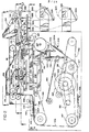
- the section of film drawn into the machine is severed by a knife 120 and the film is folded under the package 100 by a rear underfolder 122 and side underfolders 124 which are activated by the rear underfolder 122.
- the package 100 with a film section thus underfolded on three sides is pushed out of the film underfolding area of the machine by a package pusher 126.
- the package pusher 126 includes a cam roller 128 which lifts the package holddown 116 off the package 100 as the pusher 126 is advanced to facilitate ejection of the package from the film underfolding area by the pusher 126.
- the remaining fourth edge of the film is folded under the package 100 as the package advances onto a conveyor 130.
- the conveyor 130 transports the wrapped package 100 to the sealing and conveying apparatus 132 where the underfolded film is heat sealed to secure the wrapping of the package 100.
- a pivotally mounted package sealing holddown 134 engages the upper surface of the package 100 and forces or holds it firmly against the sealing/conveying apparatus 132.
- a main drive shaft 140 is driven by an electric motor (not shown) and a gear reduction drive (not shown) through a chain 142.
- the main drive shaft 140 includes four machine operating cams with an elevator cam 144 being shown in Fig. 2.
- the main drive shaft 140 also drives a chain 146 around sprockets 147 and, in turn, the platforms 106 which are positioned equidistant from one another and connected to the chain 14G.
- the package feed-in pusher 104 is mounted to a chain 148 which is driven by the chain 146.
- the chain 148 is one-third of the length of the chain 146 so that each time the package feed-in pusher 104 is advanced into the feed-in tray 102, a platform 106 precedes and is synchronized with it.
- the main drive shaft 140 also drives a potentiometer 150 from which a system clock is derived.
- a system clock is derived. The operation of the system clock in the control of the wrapping machine will be fully described hereinafter.
- the elevator 108 is supported on a platform 152 and is readily removable therefrom for cleaning purposes.
- the platform 152 is supported on a shaft 154 which is reciprocated in the vertical direction by a pivotally mounted elevator control arm 156 by means of the elevator cam 144 which engages a cam follower 158.
- a pivotally mounted stabilizing arm 160 is connected to the shaft 154 to maintain the shaft 154 in a generally vertical orientation throughout its reciprocating motions.
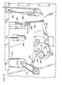
- Fig. 3 shows the right side of the wrapping machine as shown in Fig. 1 and includes two additional cam surfaces to control the film clamps 114 and the underfolders 122, 124.
- a film clamp cam 161 mounted on the drive shaft 140 engages a cam follower 162 and in turn activates a clamp lever arm 164 which reciprocates the side clamps 114 between film engaging and film stretching positions via an adjustable link 166.
- Film clamping jaws of the film side clamps 114 as best seen in Figs. 2 and 7 are closed by electrical solenoids 168 as will be described hereinafter.
- the underfolders 122, 124 are operated via a pivotally mounted lever arm 170 which includes a cam follower 172 which is driven by a cam 173 mounted on the main drive shaft 140.
- the lever arm 170 reciprocates a chain 174 which in turn reciprocates an underfolder drive chain 176, see also Fig. 8.
- a shaft 178 is driven via a chain (not shown) from the main drive shaft 140 to drive continuously chains 180 and 182.
- the chain 180 drives cams 184 shown in Figs. 2 and 6 which activate the film severing knife 120 while the chain 182 drives the conveyor 130, the sealing and conveying apparatus 132, as well as conveying belts included on the sealing holddown 134, as will be described hereinafter.
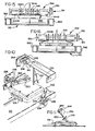
- Figs. 4 and 5 show the left side of the machine as shown in Fig. 1 and illustrate the novel mechanism for selecting the length of film sections drawn or pulled into the film wrapping machine by the gripper 110.
- the main drive shaft 140 is connected to a cam 200 which reciprocates output lever arm 202 approximately between the positions shown in Figs. 4 and 5.
- the output lever arm 202 is pivotally mounted to the wrapping machine by a bearing 203.
- An adjustable lever arm 204 taking the form of a crank in the illustrative embodiment of Figs. 4 and 5, is pivotally mounted to the distal end of the output lever arm 202 by a pin 206.
- the pin 206 is connected to a chain 207 to couple the output lever arm 202 to the chain 207 which drives the package pusher 126 through a fixed stroke.
- One end of the adjustable lever arm 204 is coupled to the gripper 110 by a link 208 and the other end of the adjustable lever arm 204 is connected to a link 209 by a universal coupler 210.
- the opposite end of the link 209 is slidingly engaged within an arcuate slot 211 formed within an adjustment guide plate 212 which is mounted to the wrapping machine.
- the adjustable link 209 can be continuously adjusted to any position along the arcuate slot 211.
- the lower end of the link 209 is positioned along the arcuate slot 21'1 by a bar 213 which engages the lower end of the link 209 and a threaded member 214 which is in turn threadedly engaged by a screw shaft 215.
- a motor 216 is coupled to the screw shaft 215 through a strain relief clutch mechanism 217.
- the screw shaft 215 can be secured against rotation by an electrically activated brake 218 which selectively secures or releases the screw shaft 215.
- a linear potentiometer 219 is coupled to the threaded member 214 and monitors the position of the threaded member 214 so that the control system of the wrapping machine can determine the adjustment of the lower end of the link 209 within the arcuate slot 211 to thereby monitor the setting of the length of film to be drawn for wrapping a package as will be described hereinafter.
- the operation of the novel film length selection mechanism can now be described with reference to Figs. 4 and 5.
- the solid line drawing of the link 209 near the left end of the arcuate slot 211 provides for maximum articulation of the adjustable lever arm 204 when the output lever arm 202 is moved to the gripper extension position shown in Fig. 4.
- This articulation can be reduced by moving the lower end of the link 209 to the right as shown in Figs. 4 and 5 in the arcuate slot 211 to a minimum film length position (shown in phantom in Fig. 4), i.e., near the extreme right end of the arcuate slot 211.
- a continuous adjustment of the film extension position of the film gripper 110 is provided between the solid line position and the phantom line position shown in Fig. 4.
- the extreme left hand and right hand positions of the link 209 within the slot 211 respectively correspond to the maximum and minimum lengths of film to be drawn into the machine for wrapping a package.
- the ability to select a variety of film extension positions is important but is only one aspect of a viable film length selection mechanism. It must be remembered that the film gripper 110 must always be moved initially to a fixed film end engaging position 112 determined by film feeding jaws so that a film end may be gripped. To this end, the arcuate slot 211 is centered upon the point of connection of the link 209 with the adjustable lever arm 204 when the lever arm 202 is in the forward, film end engaging position shown in Fig. 5. Thus, for all the continuously variable positions of the lower end of the link 209 within the arcuate slot 211, the forward position or film end engaging position of the gripper 110 is the same.
- the lower end of the link 209 can be positioned to any film extension setting between and including the maximum and minimum settings defined by the end points of the arcuate slot 211 with no effect on the positioning of the adjustable lever arm 204 when the output lever arm 202 is in the film end engaging position shown in Fig. 5.
- the length of film to be drawn into the wrapping machine is set by positioning the lower end of the link 209 to a desired position within the arcuate slot 211. Once set, a film length can be maintained indefinitely to reciprocate the film gripper 110 between the fixed film end engaging position 112 and a selected film extension position to thereby draw a preferred length of film for wrapping a plurality of packages of the same size.
- An operator of the wrapping machine places a package to be wrapped on the feed-in tray 102.
- the package is placed near the central portion of the feed-in tray 102 and ideally the package should be aligned approximately on the centerline 102A of the feed-in tray.
- a package thus placed on the feed-in tray 102 is engaged by the package feed-in pusher 104 which is continuously circulated on the chains 148.
- the package feed-in pusher 104 is preceded by and synchronized with one of the conveyor platforms 106 each of which comprises a plurality of individual rods 106A attached to and circulating with the chains 146 as previously described.
- the platform 106 which precedes the package feed-in pusher 104 is positioned immediately below the feed-in tray 102. As the package is pushed off the feed-in tray 102 by the package feed-in pusher 104, the platform 106 receives and supports the package and transports it to the elevator 108. At the elevator 108, a stop 220 engages and restrains the package and permits the platform 106 to be moved from beneath the package. The package is then supported on the upper package supporting surface of the elevator 108.
- the elevator 108 comprises a base platform 108A and a plurality of hingedly mounted slats 108B which are resiliently biased toward the upright position, for example, by a plurality of springs (not shown), to receive and support packages placed thereon.
- This structure of the elevator 108 permits the underfolders 122, 124 to collapse the elevator slats 108B and transfer support of a package to the underfolders 122, 124 as film is folded about the package as is well known in the art.
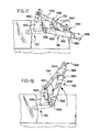
- the longitudinal sensing means comprises a lever arm 230, best seen in Figs. 2, 10 and 11, which is firmly affixed to a pivotally mounted cylindrical shaft 232.
- the lever arm 230 extends downwardly in a generally vertical direction into the package entryway.
- Two Hall effect switches 234 and 236 are coupled to the shaft 232 through adjustable collars 238 and 240 which include vanes 242 and 244 for activating the Hall effect switches 234 and 236 in accordance with the rotational orientation of the shaft 232.
- Hall effect - switches are used to prevent contact bounce which may lead to erroneous readings.
- the Hall effect switch 234 generates a signal immediately upon contact of a package with the lever arm 230 as the package is being pushed into the machine by the feed-in package pusher.104. This signal is used to determine the length of the package entering the machine as will be described hereinafter.
- the lever arm 290 includes a roller end 292 which engages a movable track 294.
- the track 294 is mechanically coupled to the right sidewall of the machine by links to maintain the track in a generally horizontal position as it is moved up and down by a solenoid 296 shown in Fig. 3.
- the lever arm 290 is lifted to rotate and close the lower gripper jaw 284 against the fixed upper jaw 280.
- the roller end 292 of the lever arm 290 permits the film gripper 110 to be moved between the fixed film end engaging position 112 and the variable film extension position.
- the trolley bar 282 rides on guide rails 296 mounted on both sides of the machine and is propelled by the novel film length selection mechanism shown in Figs. 4 and 5 through the link 208.
- the trolley bar 282 is maintained in the orientation shown throughout its reciprocating travel by chains 298 which are interconnected through a rotating shaft 300.
- Film widths usable in the disclosed film wrapping machine range between approximately thirteen (13) and nineteen (19) inches.
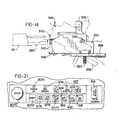
- the film feeding jaws 340, 342 and associated pinch rollers 344, 346 extend between end plates 350 which are mounted between the sidewalls of the wrapping machine to pivot about the point 352.
- the end plates 350 are placed into one position to feed narrow film through film feeding jaws 340 as shown by the solid line drawing in Fig. 14.
- the side plates 350 are pivoted about the point 352 to a second position shown by the dot-dashed line drawing of Fig. 14.
- the film feeding jaws 340 and 342 each comprises a fixed jaw 354.
- the upper film feeding jaws 340 have the lower jaw fixed while the lower film feeding jaws 342 have the upper jaw fixed.
- the movable jaw 356 of the upper film feeding jaws 340 can be pivoted upwardly away from the upper fixed jaw 354 while the movable jaw 358 of the lower film feeding jaws 342 can be pivoted downwardly away from the lower fixed jaw 354.
- Two fixed rollers 360 and 362 are mounted for rotation between the end plates 350.
- the movable jaw 356 is pivotally mounted between arms 364 and the pivotal motion of the movable jaw 356 relative to the arms 364 is limited by pins 366.
- a roller 370 is also mounted between the arms 364.
- the roller 370 is coated with rubber or other film gripping material and includes a one-way clutch to allow rotation only in the clockwise direction as shown in Fig. 12.
- the arms 364 are mounted to be pivoted about screws 372.
- the film feeding jaws 340 and associated pinch rollers 344 are maintained in their closed position as shown by the solid line drawing in Fig. 12 by springs 374 which extend between each arm 364 and an associated lever arm 376.
- the lever arms 376 bias the springs 374 to maintain the arms 364 in the closed position.
- the lever arms 376 are rotated clockwise to the dotted line position shown in Fig. 12.
- tension is relieved from the springs 374.
- tabs 378 engage the lower surfaces 380 of the arms 364 to lift the arms 364 and open the jaws 340 and separate the pinch rollers 344.
- Detents (not shown) on the lever arms 376 and the end plates 350 maintain the lever arms 376 in the closed and opened positions which are thereby stably determined. Once placed in the opened position, narrow film can be readily fed between the pinch rollers 344 and the upper film feeding jaws 340 using both hands.
- the lower film feeding jaws 342 are also mounted to open for film threading purposes.
- the movable jaw 358 is pivotally mounted between arms 381 with the pivotal movement of the jaw being limited by pins 382.
- a roller 384 which comprises the second of the pinch rollers 346 is mounted between the arms 381.
- the roller 384 is covered with rubber or other film gripping material and includes a one-way clutch which permits the roller 384 to rotate only in the counter-clockwise direction as shown in Fig. 12.
- the arms 381 are mounted for pivotal movement about a screw 386.
- Lever arms 388 are mounted to rotate about bolts 390 and are spring loaded against the end plates 350 by springs 392.
- the lever arms 388 can be rotated between a jaws closed position shown by the solid line drawing in Fig. 13 and a jaws opened position shown by the dotted line drawing in Fig. 13.
- a cam surface 394 engages the lower surface 393 of the arms 381, once they have been manually raised by a machine operator, to fully close and lock the lower jaws 342 and the pinch rollers 346 into the closed, film feeding position.
- Detents (now shown) on the lever arms 388 and the end plates 350 similarly serve to define the jaws opened and jaws closed positions of the lever arms 388.
- the jaws 340 when the film feeding jaws 342 and pinch rollers 346 are opened, wide film can be conveniently threaded between and spread across the film feeding jaws 342 and the pinch rollers 346 using both hands. The jaws and pinch rollers can then be closed by manually raising the arms 381 and closing the lever arms 388.
- the film feeding apparatus is rotated about the pivot point 352 by two solenoids.396 and 398, shown in Fig. 4.
- the solenoid 396 pushes the film feeding apparatus into the upper, wide film feeding position and the solenoid 398 pulls the film feeding apparatus into the lower, narrow film feeding position. Due to the mass of the film feeding apparatus, the solenoid 396 is larger than the solenoid 398 which is aided by the gravitational tendency of the film feeding apparatus to assume the narrow film feeding position.
- the connection of the solenoids 396 and 398 to the film feeding apparatus is best seen in Figs. 7 and 13 at 400.
- Fig. 7 also shows the side clamps 114 which engage opposite sides of a film sheet which has been drawn into the machine by the gripper 110 and stretch it outwardly toward the sides of the film wrapping machine. Stretching of the narrow width film 320A is generally illustrated by the dashed stretched film lines 320B in Fig. 7.
- the film clamps 114 are shown in their inserted position by the dashed line drawing and in their extended, stretching position by the solid line drawing.
- the side clamps 114 are reciprocated between the inserted and extended positions as previously described with reference to Fig. 3.
- a link 114A extends from a tab 114B below the hinged mounting 114C of the side clamp mounted in the right hand side of the machine as shown in Fig.
- Fig. 8 illustrates the next level progressing upwardly through the machine and includes a plan view of the underfolders 122, 124, the conveyor 130 and the sealing/conveying apparatus 132.
- the underfolders 122, 124 are driven by the chain 176 as described with reference to Fig. 3.
- the chain 176 drives a shaft 420 which in turn drives underfolder drive chains 422 which are connected to a trolley bar 424.
- the trolley bar 424 rides on guide rails 426 connected to the sides of the wrapping machine.
- the side underfolders 124 include angular extensions 124A and are pivotally mounted to a support bar 428 extending between the sides of the wrapping machine.
- a curvilinear cam surface 430 is formed into each of the side underfolders 124.
- Each cam surface 430 receives a cam driver 432, each of which is firmly connected to and moves with the trolley bar 424.
- the side underfolders 124 are simultaneously pivoted inwardly.
- film is folded under three sides of a package by the simultaneous action of the rear underfolder 122 and the side underfolders 124.
- the extensions 124A tuck in the sides of the leading film edge before the leading film edge is folded under the package by being pushed onto the conveyor 130 by the package pusher 126.
- the rear underfolder 122 comprises a plurality of rods 434 which are mounted between support arms 436 with each of the rods 434 being freely rotatable within the side arms 436.
- the side support arms 436 are spring mounted to the trolley bar 424 by compression springs 437 (see Fig. 2) which encircle bolts 438 so that the support arms 436 are resiliently forced against the trolley bar 424.
- This mounting arrangement for the support arms 436 permits the rear underfolder 122 to be moved away from the trolley bar 424 to facilitate the removal of package jams which may occur between the rear underfolder 122 and the side underfolders 124, the conveyor 130 or other parts of the wrapping machine.
- the sealing/conveying apparatus 132 comprises a heating pad 450 and a continuous conveyor belt 454.
- the temperature of the heating pad 450 is adjustable via a temperature control which is adjusted by rotating a knob 452.
- the conveyor belt 454 is carried over the heating pad 450 by a shaft 456 which is driven by the chain 182 as described with reference to Fig. 3.
- the shaft 456 also drives the conveyor 130 through a chain 458 and the package sealing holddown 134 via a pulley 460 and a "crossed" belt 462 shown in Figs. 17 and 18.
- the belt 462 is crossed so that the conveyor 454 and the holddown 134 are rotated counter to one another to complement each-other in conveying packages from the machine over the heating pad 450.
- the sealing/conveying apparatus 132 is pivotally mounted to the shaft 456.
- the conveyor 130 comprises a plurality of belts 464 which are mounted between a rotating shaft 466 and a shaft 468 which is driven by the chain 458.
- the shafts 466 and 468 include grooves for receiving the belts 464.
- a freely rotating roller 470 is mounted within the belts 464 to support the upper portion of the belts if they are depressed by packages being conveyed by the conveyor 130.
- Fig. 9 illustrates the next level progressing upwardly through the film wrapping machine and includes a plan view of the package holddown 116, the package pusher 126 and the pivotally mounted package sealing holddown 134.
- the package holddown 116 is positioned over the elevator 108 and provides a downward force on packages while film is folded under them by the underfolders 122, 124.
- the package holddown l16 is pivotally mounted at 118 and can be easily removed from the mounting 118 to provide access into the central portion of.the machine.
- the package pusher 126 is hingedly mounted to a trolley bar 500 which rides on rails 502 secured to the sidewalls of the wrapping machine through spacers 504.
- the trolley bar-500 is connected to chains 506 which are driven through a shaft 508 by the chain 207 as previously described with reference to Figs. 4 and 5.
- the cam roller 128 is mounted to the trolley bar 500 for lifting the package holddown 116 off packages as the pusher 126 pushes them onto the conveyor 130 and thereby completes the wrapping of packages by underfolding the leading film edge.
- the package pusher 126 is mounted to the trolley bar 500 by a hinge 510.
- the hinge 510 permits.the package pusher 126 to be elevated together with the rear underfolder 122 to remove jammed packages from the machine.
- Lifter blocks 512 are provided on either side of the pusher 126 to prevent the pusher 126 from jamming against or impeding the upward motion of the rear underfolder 122 as it is lifted.
- the lifter blocks 512 also serve to lift the pusher 126 by contact with the rear underfolder 122 as it is lifted.
- the package sealing holddown 134 comprises side members 530 which are rigidly interconnected by a web 532 and a cylindrical rod 534 to form a generally rectangular framework, see Fig. 9.
- the side . members 530 are mounted for free pivotal movement about a rotatable cylindrical shaft 536.
- the shaft 536 is driven by the belt 462 which engages a pulley 538 firmly affixed to the shaft 536 (see also Figs. 8, 16 and 17).
- the shaft 536 is mounted for rotation in side frame members 540 which are affixed to the sides of the machine through spacers 542.
- a generally cylindrical holddown roller 544 comprises a central section 544A of a first diameter and two outer sections 544B connected to the central section 544A by frustum sections 544C.
- the generally cylindrical roller 544 is mounted for rotation between the side members 530 and is driven by a plurality of belts 546 from a multiply grooved pulley 548 which is firmly affixed to the shaft 536.
- the central section 544A of the generally cylindrical roller 544 includes a plurality of grooves for receiving the belts 546.
- the belts 546 have a generally circular cross-section; however, other shapes of drive belts can be incorporated into the novel sealing holddown 134.
- the pulley 548 is driven in a counter-clockwise direction as viewed from the right side of the machine, as shown in Fig. 1, by the belt 462 to assist the sealer/conveyor apparatus 132 in conveying wrapped packages from the machine (see Fig. 16).
- Figs. 15 and 16 show different width and height packages passing between the sealing/conveying apparatus 132 and the package holddown roller 544.
- the sealing holddown 134 maintains a force against the top of a package passing across the sealing/conveying apparatus 132 and is rotated by the belts 546 in a direction to complement the conveying action of the sealing/conveying apparatus 132.
- the sealing holddown 134 is pivotally mounted as previously described so that the holddown can move upwardly as packages pass thereunder.
- a roller (not shown) comparable to the roller 470 for the conveyor 130 may be mounted within the belts 546 to support the lower portions thereof if the belts are deformed by packages exiting the machine.
- the shape of the holddown roller 544 has been found to provide improved sealing contact between wrapped packages and the sealing/conveying apparatus 132.
- the outer sections 544B of the roller concentrate the holddown force toward the outer side edges of the tray and may even rest against the upper tray edges, see Fig. 15.
- the force is concentrated upon the outer fringe portions of the tray where the majority of the film fold is accumulated and the film fold is then compacted and sealed.
- the roller 544 tends to spread the force laterally across the package and still ensure proper heat sealing of wrapped packages. It is noted that higher packages tend to have more weight and, hence, the force provided by the sealing holddown is less important.
- the interrelationship between the sealing/ conveying apparatus 132 and the sealing holddown 134 is shown in Figs. 17 and 18.
- the sealing/ conveying apparatus 132 When in the machine operating, package conveying position, the sealing/ conveying apparatus 132 is supported on the wrapping machine frame by an extension 560.
- the package sealing holddown 134 is supported on housings 562 by side plates 564 which are constructed from trifluoroethylene, nylon or a similar material.
- the film feeding apparatus is orie.nted generally below the conveyor 130.
- the sealing/conveying apparatus 132 is pivoted upwardly by manually lifting a handle 566.
- the side plates 564 of the sealing holddown 134 are formed to ride against the housings 562 of the sealing/conveying apparatus 132 as that apparatus is pivotally raised from the position shown in Fig. 17 to the position shown in Fig. 18.
- a notch 568 is provided in each of the side plates 564 to engage the edges of the housings 562 when the sealing/conveying apparatus 132 is placed into its fully elevated position as shown in Fig. 17. This maintains the sealing/conveying apparatus 132 and the sealing holddown 134 in an elevated position out of the operator's way to provide free access to the film' feeding apparatus.
- the mechanical operation of the wrapping machine is controlled by the main drive shaft 140 which drives the four control cams 144, 161, 173, 200 and the various chain drives previously described.
- the electrical operation of the wrapping machine is controlled by a microprocessor 600 and associated input/output (I/O) modules 602 which monitor and control electrical devices of the machine in synchronism with the main drive shaft 140.
- Input signals to the microprocessor 600 are received on inputs 604 of the I/O modules 602 and output display and control signals are generated on outputs 606 of the I/O modules 602.
- the wrapping machine is controlled and monitored by an operator through a control panel 607 as shown in Figs. 1 and 21.
- the various switches and displays although to some extent self-explanatory due to functional labelling, will be referred to and explained as the control system is described.
- a "power on" display 607A is lighted by a transformer (not shown).
- a start switch 607B is depressed and to stop the machine an easily accessible, oversized stop switch 607C is depressed.
- Activation of the stop switch 607C also provides for emergency stops of the wrapping machine by stopping the machine within a minimum period of time.
- the analog voltage signal from the potentiometer 150 is converted into binary coded clock counts by an eight bit analog-to-digital (A/D) converter 608 (see Fig. 19).
- the A/D converter 608 is driven from the clock of the microprocessor 600 through a divider or counter circuit 609.
- the eight bit clock counts generated by the A/D converter 604 define 256 distinct operating points for each machine cycle.
- the clock counts are monitored by the microprocessor 600 to perform required electrical operations upon the occurrence of specific clock counts.
- Operation of the microprocessor control system of the wrapping machine can best be understood by referring to the system timing diagram shown in Fig. 20. Clock counts generated by the A/D converter 608 are shown across the top of the system timing diagram. The clock counts and, hence, the operations of the microprocessor control system are synchronized with the mechanical operation of the wrapping machine by setting the clock count of 168 as the point when the package pusher 104 engages a package positioned at the rear-most end 102A of the feed-in tray 102 as shown in Fig. 1.
- a clock count of 194 must be received by the microprocessor 600.
- the microprocessor 600 Upon receipt of the 194 clock count, the microprocessor 600 initiates sensing of the length, width and height characteristics of a package to be wrapped by enabling the package sensing operation. If an auto- film set switch 607E is operated, the machine automatically selects the width and length of film to be used to wrap each package based on the sensed package size characteristics.
- the output signal from the Hall effect switch 234 is monitored through an input Tl of the microprocessor 600 to sense whether a package is present and, if present, the length of the package.
- the package length is determined. The earlier the switch 234 is operated, the longer the package. If no package is sensed, film will not be drawn into the machine for that machine cycle.
- D the largest package size
- C between and including clock counts of 206 to 210
- B between and including.clock counts of 211 to 219
- A the smallest package size
- the four film lengths have been found to be satisfactory for wrapping a large variety of package sizes.
- the film is efficiently used by the wrapping machine while the number of necessary adjustments of the film length selection mechanism shown in Figs. 4 and 5 is reduced to provide longer life.
- the Hall effect switch 236, as previously described, is controlled from the lever arm 230 to detect the height of packages to be wrapped. Reading of the switch 236 is enabled by the microprocessor 600 between and including clock counts of 218 to 240 to detect the height of packages entering the wrapping machine. If the lever arm 230 is deflected by a package equal to or greater than approximately two and one-half (2-1/2) inches high during this portion of the machine cycle, a flag is set indicating that a high package is coming into the machine. The high package flag is read at a clock count of 240 and thereafter cleared for the next package sensing operation.
- next longer film increment i.e., the next larger package size is indicated with the exception that if the minimum film length was initially indicated, the minimum film length will still be used. Of course, if the maximum film length was initially indicated, no adjustment will be made beyond that maximum film length which is used to wrap the package.
- a wide package test is performed.
- a wide package is defined as a package approximately nine (9) inches in width or wider, of course, the definition of a wide package is adjustable in the disclosed wrapping machine.
- a wide package is indicated if both Hall effect switches 226 are activated by deflections of the swing arms 222 by a package entering the wrapping machine. Both switches must be activated since an operator may place a package off-center so that one of the switches 226 may be operated by a narrow package.
- wide film from the roll 322 will be selected at a clock count of 240 by operating the solenoid 396 as previously described. Once a film width has been selected, that width film continues to be provided to the wrapping machine until the other film width is required in accordance with the characteristics of a package sensed during the package sensing window.
- the package sensing window extends between clock counts of 194 and 240 and includes the high package test and wide package test.
- the microprocessor 600 determines what film length is to be used to wrap the package that was just sensed.
- the film width to be used was previously determined at a clock count of 240.
- Film lengths are determined by the sensed package size with the shortest of the four film lengths being drawn for an A size package and incremental increases for B, C and D size packages. Also, as previously noted, if a high package has been detected, the next longer film length will be drawn unless the minimum or maximum film length was indicated.
- the present setting of the film length selection mechanism shown in Figs. 4 and 5 is read from the linear potentiometer 219. If the desired film length and the present setting are the same, no adjustment is necessary; however, if the two are different, the film length selection mechanism must be adjusted to pull the desired length of film.
- the linear potentiometer 219 generates an analog output signal which is directly proportional to the positioning of the lower end of the link 209 along the arcuate slot 211.
- the analog output signal of the linear potentiometer 219 is converted into a four bit binary code by an A/D converter 610 (see Fig. 19).
- This four bit code defines sixteen different film lengths which could be selected by the microprocessor 600'of the electrical control system for the disclosed wrapping machine. As previously noted,.in the disclosed embodiment only four of the available.sixteen film lengths are selected. These four film lengths are the same for both of the two different film widths. It is noted that all sixteen film lengths could be selected if desired and also additional lengths could be defined by the use of an analog-to-digital converter having greater than a four bit output signal.
- the disc brake 218 which normally locks the screw shaft 215 in an adjusted position, is released; and, if the film length to be drawn is less than the present setting of the film length selection mechanism, a motor reversing relay (not shown) is operated to precondition the motor 216 to operate in the proper direction for the required adjustment.
- the jam test is initiated.
- the jam test is performed by monitoring the clock counts during each operating cycle of the microprocessor 600.-
- the microprocessor operating cycle is short compared to the time (approximately 7 milliseconds) between consecutive clock counts.
- Monitoring of the clock counts is performed by incrementing an eight (8) bit jam counter for each microprocessor operating cycle and clearing the jam counter for each change of the clock count.
- the jam counter is maintained within the microprocessor 600 and, hence, is not physically shown in Fig. 19. During smooth operating portions of the film wrapping machine cycle, a count of approximately fourteen microprocessor operating cycles can be anticipated between consecutive clock counts.
- a jam condition is indicated if the jam counter overflows as the result of the main drive shaft 140 hesitating for a sufficient period of time.
- the position of the potentiometer 150 is similarly delayed and the corresponding clock count does not change, which permits the count in the jam counter to accumulate.
- power to the machine motor is interrupted.
- the jam test is disabled at a clock count of 252 as previously described since the "blank portion" of the potentiometer 150 encountered between clock counts of 255 and 0 could be indicated as a machine jam.
- the jam test could have been disabled between clock counts of 255 and 0, however, since other operations are performed at clock counts of 252 and 16, these clock counts were chosen for convenience.
- the tension of the film on wrapped packages is controlled by setting the operate and release times of the film side clamps 114 and the release times of the film gripper 110 in synchronism with or in phased.relation to the underfolders 122, 124.
- the operate and release times of the film side clamps 114 correspond to the film width selected and the release times of the film gripper 110 correspond to the film width selected and also to the package length as determined by the package sensing system.
- the operate time of the film gripper 110 is the same regardless of the film width or length since the film gripper 110 must always operate when it is in the film end engaging position 112 as shown in phantom view in Fig. 7. Hence, whenever film is drawn into the machine, the film gripper 110 is operated at a clock count of 43 regardless of the length or width of the film to be drawn.
- the film side clamps 114 are operated at set clock counts of 134 for narrow film and 146 for wide film. Operation of the film side clamps 114 at a clock count of 134 for the narrow film 320A provides for gripping narrow film when the side clamps are at their innermost position. By delaying operation of the side clamps 114 until a clock count of 146 for the wide film 322A, the side clamps 114 have started their outward movement. Thus, while the wide film 322A is gripped further in from the film side edges than the narrow film, the film clamps l14 are more widely separated from one another when the wide film is gripped. Of course, the exact points of application of the clamps 114 can be adjusted by changing the clock counts at which the clamps are activated.
- the release of the side clamps 114 is set at a base clock count of 189 for narrow film and at a base clock count of 184 for wide film.
- the base clock counts for the release of the film gripper 110 depend upon both the film width selected and the size of the package being wrapped.
- the base clock counts for gripper release are: D package size, 193 clock count; C package size, 194 clock count; B package size, 195 clock count; and A package size, 195 clock count.
- the base clock counts for gripper release are as follows: D package size, 185 clock count; C package size, 192 clock count; B package size, 194 clock count; and A package size, 194 clock count.
- the actual release clock counts for the side film clamps 114 and the film gripper 110 are calculated from the defined base release clock counts.
- the actual release clock counts are calculated to permit compensation for mechanical changes which may occur due to wear and aging of the wrapping machine over its operating life. Such changes can effect the synchronization of the underfolders 122, 124 with the release times of the side clamps 114 and the film gripper 110.
- the film wrapping machine may be operated in a variety of ambient environmental conditions, such as varying temperature and humidity, and also a variety of film gauges may be used in the film wrapping machine.
- Compensation for such aging and environmental conditions is provided in the disclosed wrapping machine by adjusting the actual release clock counts for the side film clamps 114 and the film gripper 110 by up.to plus or minus seven clock-counts from the base clock counts.
- the adjustments are provided by means of adjustment switches 614.
- Four separate switches, 614A through 614D, are provided to adjust the release time individually for the release of the film clamps for wide film (614B); the release of the film gripper for wide film (614A); the release of the film clamps for narrow film (614D); and the release of the film gripper for narrow film (614C).
- a tension adjustment switch 616 is provided to adjust the base release clock counts of the film gripper 110 by from zero to plus seven clock counts.
- the tension control switch 616 is a thumb wheel switch controlled by the operator of the machine.
- the setting of the switch 616 is used to calculate the gripper release clock counts for both narrow and wide film widths.
- the settings of the adjustment switches 614 are normally changed only infrequently due to aging or changed ambient conditions with changes typically being made during routine maintenance. Hence, the switches 614 are normally available only to maintenance service personnel and not to the machine operator.
- the actual release clock counts are calculated by combining the base release clock counts previously defined and the setting of the corresponding film clamp adjustment switch 614B or 614D.
- the actual release clock count is calculated by combining the base clock counts previously defined with both the setting of the corresponding wide or narrow film gripper adjustment" switch 614A or 614C and the setting of the tension control switch 616.
- a package flag is maintained by the microprocessor.600.
- the package flag is cleared prior to each package sensing window (between and including clock counts of 194 to 232) and remains cleared if no package is sensed. If the package flag is cleared, no film is drawn into the wrapping machine even though the mechanical operation of the machine continues. If a package is sensed during the package sensing window, the package flag is set. If the package flag is set, film is drawn into the machine to wrap the sensed package.
- the microprocessor 600 maintains a count of the number of consecutive wrapping machine cycles during which the package flag remains cleared and the wrapping machine is stopped after a programmable number of operations, preferably seven (7) operations.
- an adjustment of the film length mechanism shown in Figs. 4 and 5, if necessary, is initiated by energizing the motor 216.
- the direction of operation of the motor 216 was previously selected at a clock count of 252 to precondition the adjustment.
- the linear potentiometer 219 is monitored while the motor 216 operates until the setting of the film length mechanism corresponds to the desired setting.
- the motor 216 is turned off and the disc brake 218 is activated to secure the screw shaft 215 at the desired setting.
- Activation of the brake 218 prevents creeping of set adjustments of the film length selection mechanism as well as helping to prevent overshoot as adjustments are made.
- Limit switches (not shown) prevent the motor from trying to force the lower end of the link 209 beyond the ends of the arcuate slot 211.
- the disclosed wrapping machine can be incrementally operated or "jogged" in either a forward direction or in a reverse direction by operation of momentary contact switches 617A and 617B, respectively, see Fig. 21.
- Forward jog permits the machine to be operated through a complete package wrapping sequence to ensure the machine is properly set up before being operated at full speed. Operation by forward jogging does not provide a well wrapped package since machine inertia is required for smooth, actual wrapping performance.
- Reverse jog operation facilitates removal of jams from the machine.
- the reverse jog can only be activated between machine clock counts of 8 and 211 inclusive.
- the limitation on the reverse jog operation ensures that the machine is not operated in a reverse direction through the portion of mechanical operation where the underfolders 122, 124 fold down the spring loaded slats 108B of the elevator 108. Reverse operation through this portion of the machine cycle could cause damage to the machine.
- Each activation of one of the jog switches 617A or 617B provides power to the main machine motor for a time period of one clock count. Although the power is provided for only one clock count, the machine moves through more than one clock count due to the mechanical inertia created by the pulsed activation of the motor.
- the operator may also select either wide width film or narrow width film regardless of the film width which is indicated by the automatic package sensing system previously described.
- a wide film switch 620 When a wide film switch 620 is activated, the film selector presents only wide film to the film gripper 110.
- the film length drawn is still determined by the package sensing system and activation of the height switch, i.e., the Hall effect switch 236, again causes the next longer film length to be pulled, except for minimum or maximum lengths as previously described.
- the microprocessor 600 determines whether one of the film sensing switches 328 and 330 was opened due to film being drawn into the film wrapping machine. If no film was drawn, the machine is shut-down. This permits the unwrapped package to be removed from the machine and the film to be refilled or the film problem corrected without contamination to the wrapping machine which could occur if an uncovered package was moved through the wrapping machine.
- a machine stop at a clock count of 92 due to a film problem condition may facilitate threading a new roll of film into the machine in the event that the film has expired.
- a roll of film expires, a short section of the trailing end of the film will remain threaded through the corresponding film feed-in jaws 340 or 342.
- This remaining section of film can be "adhered" to the leading end of the replacement roll of film either by natural adhesion between the two, by tape or otherwise.
- the new film can then be threaded through the film feeding jaws by pulling the remaining section of film through the jaws from inside the machine.
- the disclosed wrapping machine provides two convenient and rapid techniques for threading a new roll of film into the wrapping machine.
- the control panel 607 of Fig. 21 includes various displays 624 which indicate the active film selection or operating mode of the wrapping machine. Other displays 626 on the control panel 607 indicate operations being performed by the machine. Similarly, operation of the microprocessor 600 can be monitored through a light emitting diode display panel 628, with the specific signal displayed being selected by a display function switch 630 (see Fig. 19). Cover panel interlock switches 632 stop the wrapping machine from being'operated if the cover panels are not secured on the machine.
Landscapes
- Engineering & Computer Science (AREA)
- Mechanical Engineering (AREA)
- Basic Packing Technique (AREA)
Applications Claiming Priority (2)
| Application Number | Priority Date | Filing Date | Title |
|---|---|---|---|
| US06/371,707 US4505092A (en) | 1982-04-26 | 1982-04-26 | Package sensing/film control system for film wrapping machine |
| US371707 | 1982-04-26 |
Publications (3)
| Publication Number | Publication Date |
|---|---|
| EP0092759A2 true EP0092759A2 (de) | 1983-11-02 |
| EP0092759A3 EP0092759A3 (en) | 1985-04-17 |
| EP0092759B1 EP0092759B1 (de) | 1988-08-03 |
Family
ID=23465086
Family Applications (1)
| Application Number | Title | Priority Date | Filing Date |
|---|---|---|---|
| EP83103716A Expired EP0092759B1 (de) | 1982-04-26 | 1983-04-18 | Verpackungsabtast-/Folienkontrollsystem für eine Folieneinwickelmaschine |
Country Status (5)
| Country | Link |
|---|---|
| US (1) | US4505092A (de) |
| EP (1) | EP0092759B1 (de) |
| AU (1) | AU555962B2 (de) |
| CA (1) | CA1243595A (de) |
| DE (1) | DE3377573D1 (de) |
Cited By (3)
| Publication number | Priority date | Publication date | Assignee | Title |
|---|---|---|---|---|
| EP0619227A3 (de) * | 1993-03-24 | 1994-12-28 | Awax Progettazione | Verfahren und Vorrichtung zum Umhüllen von Gegenständen mit streckbarer Folie und Hülle hergestellt durch dieses Verfahren. |
| EP0648674A1 (de) * | 1993-10-19 | 1995-04-19 | A.W.A.X. PROGETTAZIONE E RICERCA S.r.l. | Verfahren und Vorrichtung zum Umhüllen von Gegenständen mit streckbarer Folie |
| WO2022112853A1 (en) * | 2020-11-30 | 2022-06-02 | Deltapak S.R.L. | System of activation of packaging machines |
Families Citing this family (33)
| Publication number | Priority date | Publication date | Assignee | Title |
|---|---|---|---|---|
| US4709531A (en) * | 1984-05-23 | 1987-12-01 | Teraoka Seiko Co., Ltd. | Stretch film packaging machine |
| JPS61142109A (ja) * | 1984-11-30 | 1986-06-30 | 株式会社 フジパツクシステム | 包装機における包装用フィルム折込装置及びその方法 |
| US4887412A (en) * | 1987-08-07 | 1989-12-19 | Fuji Pack Systems, Ltd. | Wrapping machine |
| US4805760A (en) * | 1987-08-17 | 1989-02-21 | Hobart Corporation | Package positioning apparatus and method |
| USRE33511E (en) * | 1987-08-17 | 1991-01-01 | Hobart Corporation | Package positioning apparatus and method |
| NZ236008A (en) * | 1989-11-10 | 1992-12-23 | Ishida Scale Mfg Co Ltd | Packaging apparatus has film roll support and film transporting device that are width adjustable |
| US5414974A (en) * | 1993-08-17 | 1995-05-16 | Moore Business Forms, Inc. | Automated document handling system |
| DE69818263T2 (de) * | 1997-07-07 | 2004-07-15 | Sealed Air (Nz) Ltd. | Vorrichtung und verfahren zum herstellen von beuteln verschiedener abmessungen |
| US6363690B1 (en) | 1999-01-19 | 2002-04-02 | Ascom Hasler Mailing Systems, Inc. | Automatic measuring device and method for dispensing materials |
| ITBO20020154A1 (it) * | 2002-03-27 | 2003-09-29 | Awax Progettazione | Pinza mobile e relativi mezzi d'azionamento , per le macchine adibiteal confezionamento di prodotti con film estensibile |
| US7568327B2 (en) | 2003-01-31 | 2009-08-04 | Lantech.Com, Llc | Method and apparatus for securing a load to a pallet with a roped film web |
| US7386968B2 (en) * | 2005-03-30 | 2008-06-17 | Sealed Air Corporation | Packaging machine and method |
| US20060218884A1 (en) * | 2005-03-30 | 2006-10-05 | Sealed Air Corporation | Adjustable infeed bed for packaging apparatus |
| US7707801B2 (en) | 2005-04-08 | 2010-05-04 | Lantech.Com, Llc | Method for dispensing a predetermined amount of film relative to load girth |
| US7607467B2 (en) * | 2006-01-17 | 2009-10-27 | Cryovac, Inc. | Web dispenser |
| AU2007221338A1 (en) | 2006-02-23 | 2007-09-07 | Lantech.Com, Llc | Method and apparatus for securing a load to a pallet with a roped film web |
| US8186896B2 (en) * | 2007-07-16 | 2012-05-29 | Cryovac, Inc. | Apparatus and method for printing and dispensing a web |
| AU2009204214B2 (en) * | 2008-01-07 | 2014-05-22 | Lantech.Com, Llc | Electronic control of metered film dispensing in a wrapping apparatus |
| US9908648B2 (en) * | 2008-01-07 | 2018-03-06 | Lantech.Com, Llc | Demand based wrapping |
| KR100933519B1 (ko) | 2008-06-23 | 2009-12-23 | 주식회사 삼표 | 양감지 센서 |
| CA2814398C (en) | 2010-10-29 | 2018-10-23 | Lantech.Com, Llc | Machine generated wrap data |
| CA2889570C (en) | 2012-10-25 | 2020-10-27 | Lantech.Com, Llc | Rotation angle-based wrapping |
| EP2917114B1 (de) | 2012-10-25 | 2019-12-25 | Lantech.Com, Llc | Wirksame umfangsbasierte umwicklung |
| US9932137B2 (en) | 2012-10-25 | 2018-04-03 | Lantech.Com, Llc | Corner geometry-based wrapping |
| EP3461754B1 (de) | 2013-02-13 | 2020-04-29 | Lantech.Com LLC | Verpackungsmaterialprofilierung für eine kraftbasierte umwicklung |
| US9896229B1 (en) | 2013-08-29 | 2018-02-20 | Top Tier, Llc | Stretch wrapping apparatus and method |
| SMT202400137T1 (it) | 2014-01-14 | 2024-05-14 | Lantech Com Llc | Regolazione dinamica del parametro di forza di avvolgimento in risposta a forza di avvolgimento monitorata e/o per la riduzione di rottura della pellicola |
| US10926906B2 (en) | 2014-10-07 | 2021-02-23 | Lantech.Com, Llc | Load stability-based wrapping |
| WO2017053603A1 (en) | 2015-09-25 | 2017-03-30 | Lantech.Com, Llc | Stretch wrapping machine with automatic load profiling |
| US11667416B2 (en) | 2017-09-22 | 2023-06-06 | Lantech.Com, Llc | Load wrapping apparatus wrap profiles with controlled wrap cycle interruptions |
| WO2020033306A1 (en) | 2018-08-06 | 2020-02-13 | Lantech.Com, Llc | Stretch wrapping machine with curve fit control of dispense rate |
| WO2021050420A1 (en) | 2019-09-09 | 2021-03-18 | Lantech.Com, Llc | Stretch wrapping machine with dispense rate control based on sensed rate of dispensed packaging material and predicted load geometry |
| EP4031455A4 (de) | 2019-09-19 | 2024-04-03 | Lantech.Com, Llc | Klassifizierung von verpackungsmaterial und/oder werksprofilen |
Family Cites Families (13)
| Publication number | Priority date | Publication date | Assignee | Title |
|---|---|---|---|---|
| US2227398A (en) * | 1939-07-14 | 1940-12-31 | Micro Westco Inc | Wrapping material measuring device |
| US3029571A (en) * | 1960-08-16 | 1962-04-17 | Du Pont | Apparatus for dispensing wrapping materials |
| US3182539A (en) * | 1961-03-14 | 1965-05-11 | Jr Lowdon Richard Williams | Paper feeding and cutting machine |
| US3429098A (en) * | 1965-10-24 | 1969-02-25 | Corley Miller Inc | Automatic wrapping machine |
| CH503616A (de) * | 1969-05-20 | 1971-02-28 | Automac Ind Italiana Costruzio | Verfahren und Maschine zur Verpackung von Packstücken in dehnbaren Folien aus Weichkunststoff |
| DE2256360A1 (de) * | 1972-11-17 | 1974-05-22 | Finsterhoelzl Rafi Elekt | Kontaktloser taster und schalter |
| IT995651B (it) * | 1973-10-05 | 1975-11-20 | Smail Srl | Procedimento per l avvolgimento e l impacchettamento di prodotti disposti in contenitori vassoi e scatole con pellicola estendibile trasparente e macchina per la realizzazione dello stesso |
| US4075815A (en) * | 1976-04-30 | 1978-02-28 | Franklin Electric Subsidiaries, Inc. | Automatic package wrapping machine |
| US4205501A (en) * | 1977-04-06 | 1980-06-03 | Reliance Electric Company | Wrapping apparatus |
| US4134246A (en) * | 1977-04-06 | 1979-01-16 | Reliance Electric Company | Apparatus for wrapping with stretch film |
| US4180962A (en) * | 1977-04-06 | 1980-01-01 | Reliance Electric Company | Wrapping apparatus |
| FI58465C (fi) * | 1979-10-19 | 1981-02-10 | Waertsilae Oy Ab | System foer frammatning av foerpackningsomslag pao stora pappersrullar |
| IT1131751B (it) * | 1980-07-22 | 1986-06-25 | Pittacus Ag | Macchina procedimento per il confezionamento di prodotti mediante avvolgimento di una pellicola di materiale plastico attorno a vassoi di dimensioni varibili contenenti i detti prodotti |
-
1982
- 1982-04-26 US US06/371,707 patent/US4505092A/en not_active Expired - Lifetime
-
1983
- 1983-03-21 AU AU12638/83A patent/AU555962B2/en not_active Ceased
- 1983-03-24 CA CA000424385A patent/CA1243595A/en not_active Expired
- 1983-04-18 DE DE8383103716T patent/DE3377573D1/de not_active Expired
- 1983-04-18 EP EP83103716A patent/EP0092759B1/de not_active Expired
Cited By (6)
| Publication number | Priority date | Publication date | Assignee | Title |
|---|---|---|---|---|
| EP0619227A3 (de) * | 1993-03-24 | 1994-12-28 | Awax Progettazione | Verfahren und Vorrichtung zum Umhüllen von Gegenständen mit streckbarer Folie und Hülle hergestellt durch dieses Verfahren. |
| US5528881A (en) * | 1993-03-24 | 1996-06-25 | A.W.A.X. Progettazione E Ricerca S.R.L. | Process and machine for wrapping products with stretchable film, and wrapping formed by this process |
| US5595042A (en) * | 1993-03-24 | 1997-01-21 | A.W.A.X. Progettazione E Ricerca S.R.L. | Process and machine for wrapping products with stretchable film, and wrapping formed by this process |
| EP0648674A1 (de) * | 1993-10-19 | 1995-04-19 | A.W.A.X. PROGETTAZIONE E RICERCA S.r.l. | Verfahren und Vorrichtung zum Umhüllen von Gegenständen mit streckbarer Folie |
| US5603198A (en) * | 1993-10-19 | 1997-02-18 | A.W.A.X. Progettazione E Ricerca S.R.L. | Process and apparatus for wrapping articles with stretchable film |
| WO2022112853A1 (en) * | 2020-11-30 | 2022-06-02 | Deltapak S.R.L. | System of activation of packaging machines |
Also Published As
| Publication number | Publication date |
|---|---|
| EP0092759A3 (en) | 1985-04-17 |
| EP0092759B1 (de) | 1988-08-03 |
| DE3377573D1 (en) | 1988-09-08 |
| AU1263883A (en) | 1983-11-03 |
| US4505092A (en) | 1985-03-19 |
| CA1243595A (en) | 1988-10-25 |
| AU555962B2 (en) | 1986-10-16 |
Similar Documents
| Publication | Publication Date | Title |
|---|---|---|
| US4505092A (en) | Package sensing/film control system for film wrapping machine | |
| US4501106A (en) | Wrapping control system for film wrapping machine | |
| US4501105A (en) | Film supply monitor for film wrapping machine | |
| US4543766A (en) | Packaging system | |
| EP0092758B1 (de) | Folieneinwickelmaschine mit Folienlängenwahlanordnung | |
| US4513558A (en) | Jam detection and removal for wrapping machine | |
| US5157903A (en) | Film-folding device for packaging apparatus | |
| US4674269A (en) | Wrapping machine | |
| US5205104A (en) | Devices for supplying and transporting film for packaging apparatus | |
| EP0092760B1 (de) | Kontrollsystem für eine Folieneinwickelmaschine | |
| EP0223215B1 (de) | Vorrichtung zum Selektieren und Zuführen von Bandmaterial | |
| CA1295928C (en) | Package wrapping method and machine | |
| US4958479A (en) | Package wrapping method and machine | |
| US4507904A (en) | Film and package handling apparatus for wrapping machine | |
| EP0120333B1 (de) | Vorrichtung zum Einpacken, Wiegen und Etikettieren von Waren | |
| CN113165758A (zh) | 包装机及产品包装方法 | |
| US3546836A (en) | Process and equipment for packaging articles | |
| JPS63248612A (ja) | 包装装置 | |
| EP0626311A1 (de) | Transporteinrichtung für Pakete | |
| JPS6160410A (ja) | 包装機の折り込み機構 | |
| JPH0549524B2 (de) | ||
| JPH08282613A (ja) | 包装装置 | |
| HK40053229A (en) | Packaging machine and product packaging method | |
| JPH08169408A (ja) | ストレッチフィルム包装機 | |
| HK40053230A (en) | Packaging machine |
Legal Events
| Date | Code | Title | Description |
|---|---|---|---|
| PUAI | Public reference made under article 153(3) epc to a published international application that has entered the european phase |
Free format text: ORIGINAL CODE: 0009012 |
|
| AK | Designated contracting states |
Designated state(s): CH DE FR GB IT LI |
|
| PUAL | Search report despatched |
Free format text: ORIGINAL CODE: 0009013 |
|
| AK | Designated contracting states |
Designated state(s): CH DE FR GB IT LI |
|
| 17P | Request for examination filed |
Effective date: 19850921 |
|
| 17Q | First examination report despatched |
Effective date: 19860714 |
|
| RAP1 | Party data changed (applicant data changed or rights of an application transferred) |
Owner name: HOBART CORPORATION (A CORPORATION OF THE STATE OF |
|
| RAP1 | Party data changed (applicant data changed or rights of an application transferred) |
Owner name: HOBART CORPORATION (A CORPORATION OF DELAWARE) |
|
| GRAA | (expected) grant |
Free format text: ORIGINAL CODE: 0009210 |
|
| AK | Designated contracting states |
Kind code of ref document: B1 Designated state(s): CH DE FR GB IT LI |
|
| ITF | It: translation for a ep patent filed | ||
| REF | Corresponds to: |
Ref document number: 3377573 Country of ref document: DE Date of ref document: 19880908 |
|
| ET | Fr: translation filed | ||
| PLBE | No opposition filed within time limit |
Free format text: ORIGINAL CODE: 0009261 |
|
| STAA | Information on the status of an ep patent application or granted ep patent |
Free format text: STATUS: NO OPPOSITION FILED WITHIN TIME LIMIT |
|
| 26N | No opposition filed | ||
| ITTA | It: last paid annual fee | ||
| ITPR | It: changes in ownership of a european patent |
Owner name: CAMBIO SEDE;HOBART CORPORATION (A CORPORATION OF D |
|
| REG | Reference to a national code |
Ref country code: CH Ref legal event code: PFA Free format text: PREMARK FEG CORPORATION |
|
| REG | Reference to a national code |
Ref country code: FR Ref legal event code: CD |
|
| REG | Reference to a national code |
Ref country code: GB Ref legal event code: 732E |
|
| REG | Reference to a national code |
Ref country code: CH Ref legal event code: PUE Owner name: PREMARK FEG CORPORATION TRANSFER- PREMARK FEG L.L. |
|
| REG | Reference to a national code |
Ref country code: FR Ref legal event code: TP |
|
| PGFP | Annual fee paid to national office [announced via postgrant information from national office to epo] |
Ref country code: FR Payment date: 20010330 Year of fee payment: 19 |
|
| PGFP | Annual fee paid to national office [announced via postgrant information from national office to epo] |
Ref country code: DE Payment date: 20010402 Year of fee payment: 19 |
|
| PGFP | Annual fee paid to national office [announced via postgrant information from national office to epo] |
Ref country code: GB Payment date: 20010403 Year of fee payment: 19 |
|
| PGFP | Annual fee paid to national office [announced via postgrant information from national office to epo] |
Ref country code: CH Payment date: 20010411 Year of fee payment: 19 |
|
| REG | Reference to a national code |
Ref country code: GB Ref legal event code: IF02 |
|
| PG25 | Lapsed in a contracting state [announced via postgrant information from national office to epo] |
Ref country code: GB Free format text: LAPSE BECAUSE OF NON-PAYMENT OF DUE FEES Effective date: 20020418 |
|
| PG25 | Lapsed in a contracting state [announced via postgrant information from national office to epo] |
Ref country code: LI Free format text: LAPSE BECAUSE OF NON-PAYMENT OF DUE FEES Effective date: 20020430 Ref country code: CH Free format text: LAPSE BECAUSE OF NON-PAYMENT OF DUE FEES Effective date: 20020430 |
|
| PG25 | Lapsed in a contracting state [announced via postgrant information from national office to epo] |
Ref country code: DE Free format text: LAPSE BECAUSE OF NON-PAYMENT OF DUE FEES Effective date: 20021101 |
|
| GBPC | Gb: european patent ceased through non-payment of renewal fee |
Effective date: 20020418 |
|
| REG | Reference to a national code |
Ref country code: CH Ref legal event code: PL |
|
| PG25 | Lapsed in a contracting state [announced via postgrant information from national office to epo] |
Ref country code: FR Free format text: LAPSE BECAUSE OF NON-PAYMENT OF DUE FEES Effective date: 20021231 |
|
| REG | Reference to a national code |
Ref country code: FR Ref legal event code: ST |
|
| REG | Reference to a national code |
Ref country code: LU Ref legal event code: CCP Free format text: PRODUCT NAME: VORAPAXAR OU SON SEL OU SOLVAT PHARMACOLOGIQUEMENT ADMISSIBLE; FIRST REGISTRATION: 20150119 Spc suppl protection certif: 92759 Extension date: 20280414 |