EP0092795A2 - Dispositif d'écoulement pour gaz liquéfié à basse température - Google Patents
Dispositif d'écoulement pour gaz liquéfié à basse température Download PDFInfo
- Publication number
- EP0092795A2 EP0092795A2 EP83103878A EP83103878A EP0092795A2 EP 0092795 A2 EP0092795 A2 EP 0092795A2 EP 83103878 A EP83103878 A EP 83103878A EP 83103878 A EP83103878 A EP 83103878A EP 0092795 A2 EP0092795 A2 EP 0092795A2
- Authority
- EP
- European Patent Office
- Prior art keywords
- liquefied gas
- holes
- low
- temperature liquefied
- closing
- Prior art date
- Legal status (The legal status is an assumption and is not a legal conclusion. Google has not performed a legal analysis and makes no representation as to the accuracy of the status listed.)
- Granted
Links
Images
Classifications
-
- F—MECHANICAL ENGINEERING; LIGHTING; HEATING; WEAPONS; BLASTING
- F17—STORING OR DISTRIBUTING GASES OR LIQUIDS
- F17C—VESSELS FOR CONTAINING OR STORING COMPRESSED, LIQUEFIED OR SOLIDIFIED GASES; FIXED-CAPACITY GAS-HOLDERS; FILLING VESSELS WITH, OR DISCHARGING FROM VESSELS, COMPRESSED, LIQUEFIED, OR SOLIDIFIED GASES
- F17C13/00—Details of vessels or of the filling or discharging of vessels
- F17C13/02—Special adaptations of indicating, measuring, or monitoring equipment
- F17C13/028—Special adaptations of indicating, measuring, or monitoring equipment having the volume as the parameter
-
- B—PERFORMING OPERATIONS; TRANSPORTING
- B05—SPRAYING OR ATOMISING IN GENERAL; APPLYING FLUENT MATERIALS TO SURFACES, IN GENERAL
- B05B—SPRAYING APPARATUS; ATOMISING APPARATUS; NOZZLES
- B05B1/00—Nozzles, spray heads or other outlets, with or without auxiliary devices such as valves, heating means
- B05B1/30—Nozzles, spray heads or other outlets, with or without auxiliary devices such as valves, heating means designed to control volume of flow, e.g. with adjustable passages
- B05B1/3033—Nozzles, spray heads or other outlets, with or without auxiliary devices such as valves, heating means designed to control volume of flow, e.g. with adjustable passages the control being effected by relative coaxial longitudinal movement of the controlling element and the spray head
- B05B1/304—Nozzles, spray heads or other outlets, with or without auxiliary devices such as valves, heating means designed to control volume of flow, e.g. with adjustable passages the control being effected by relative coaxial longitudinal movement of the controlling element and the spray head the controlling element being a lift valve
- B05B1/3046—Nozzles, spray heads or other outlets, with or without auxiliary devices such as valves, heating means designed to control volume of flow, e.g. with adjustable passages the control being effected by relative coaxial longitudinal movement of the controlling element and the spray head the controlling element being a lift valve the valve element, e.g. a needle, co-operating with a valve seat located downstream of the valve element and its actuating means, generally in the proximity of the outlet orifice
-
- F—MECHANICAL ENGINEERING; LIGHTING; HEATING; WEAPONS; BLASTING
- F17—STORING OR DISTRIBUTING GASES OR LIQUIDS
- F17C—VESSELS FOR CONTAINING OR STORING COMPRESSED, LIQUEFIED OR SOLIDIFIED GASES; FIXED-CAPACITY GAS-HOLDERS; FILLING VESSELS WITH, OR DISCHARGING FROM VESSELS, COMPRESSED, LIQUEFIED, OR SOLIDIFIED GASES
- F17C9/00—Methods or apparatus for discharging liquefied or solidified gases from vessels not under pressure
-
- F—MECHANICAL ENGINEERING; LIGHTING; HEATING; WEAPONS; BLASTING
- F17—STORING OR DISTRIBUTING GASES OR LIQUIDS
- F17C—VESSELS FOR CONTAINING OR STORING COMPRESSED, LIQUEFIED OR SOLIDIFIED GASES; FIXED-CAPACITY GAS-HOLDERS; FILLING VESSELS WITH, OR DISCHARGING FROM VESSELS, COMPRESSED, LIQUEFIED, OR SOLIDIFIED GASES
- F17C2203/00—Vessel construction, in particular walls or details thereof
- F17C2203/03—Thermal insulations
- F17C2203/0391—Thermal insulations by vacuum
-
- F—MECHANICAL ENGINEERING; LIGHTING; HEATING; WEAPONS; BLASTING
- F17—STORING OR DISTRIBUTING GASES OR LIQUIDS
- F17C—VESSELS FOR CONTAINING OR STORING COMPRESSED, LIQUEFIED OR SOLIDIFIED GASES; FIXED-CAPACITY GAS-HOLDERS; FILLING VESSELS WITH, OR DISCHARGING FROM VESSELS, COMPRESSED, LIQUEFIED, OR SOLIDIFIED GASES
- F17C2203/00—Vessel construction, in particular walls or details thereof
- F17C2203/06—Materials for walls or layers thereof; Properties or structures of walls or their materials
- F17C2203/0602—Wall structures; Special features thereof
- F17C2203/0612—Wall structures
- F17C2203/0626—Multiple walls
- F17C2203/0629—Two walls
-
- F—MECHANICAL ENGINEERING; LIGHTING; HEATING; WEAPONS; BLASTING
- F17—STORING OR DISTRIBUTING GASES OR LIQUIDS
- F17C—VESSELS FOR CONTAINING OR STORING COMPRESSED, LIQUEFIED OR SOLIDIFIED GASES; FIXED-CAPACITY GAS-HOLDERS; FILLING VESSELS WITH, OR DISCHARGING FROM VESSELS, COMPRESSED, LIQUEFIED, OR SOLIDIFIED GASES
- F17C2205/00—Vessel construction, in particular mounting arrangements, attachments or identifications means
- F17C2205/03—Fluid connections, filters, valves, closure means or other attachments
- F17C2205/0302—Fittings, valves, filters, or components in connection with the gas storage device
- F17C2205/0323—Valves
- F17C2205/0326—Valves electrically actuated
-
- F—MECHANICAL ENGINEERING; LIGHTING; HEATING; WEAPONS; BLASTING
- F17—STORING OR DISTRIBUTING GASES OR LIQUIDS
- F17C—VESSELS FOR CONTAINING OR STORING COMPRESSED, LIQUEFIED OR SOLIDIFIED GASES; FIXED-CAPACITY GAS-HOLDERS; FILLING VESSELS WITH, OR DISCHARGING FROM VESSELS, COMPRESSED, LIQUEFIED, OR SOLIDIFIED GASES
- F17C2205/00—Vessel construction, in particular mounting arrangements, attachments or identifications means
- F17C2205/03—Fluid connections, filters, valves, closure means or other attachments
- F17C2205/0302—Fittings, valves, filters, or components in connection with the gas storage device
- F17C2205/0323—Valves
- F17C2205/0335—Check-valves or non-return valves
-
- F—MECHANICAL ENGINEERING; LIGHTING; HEATING; WEAPONS; BLASTING
- F17—STORING OR DISTRIBUTING GASES OR LIQUIDS
- F17C—VESSELS FOR CONTAINING OR STORING COMPRESSED, LIQUEFIED OR SOLIDIFIED GASES; FIXED-CAPACITY GAS-HOLDERS; FILLING VESSELS WITH, OR DISCHARGING FROM VESSELS, COMPRESSED, LIQUEFIED, OR SOLIDIFIED GASES
- F17C2205/00—Vessel construction, in particular mounting arrangements, attachments or identifications means
- F17C2205/03—Fluid connections, filters, valves, closure means or other attachments
- F17C2205/0302—Fittings, valves, filters, or components in connection with the gas storage device
- F17C2205/0341—Filters
-
- F—MECHANICAL ENGINEERING; LIGHTING; HEATING; WEAPONS; BLASTING
- F17—STORING OR DISTRIBUTING GASES OR LIQUIDS
- F17C—VESSELS FOR CONTAINING OR STORING COMPRESSED, LIQUEFIED OR SOLIDIFIED GASES; FIXED-CAPACITY GAS-HOLDERS; FILLING VESSELS WITH, OR DISCHARGING FROM VESSELS, COMPRESSED, LIQUEFIED, OR SOLIDIFIED GASES
- F17C2221/00—Handled fluid, in particular type of fluid
- F17C2221/01—Pure fluids
- F17C2221/014—Nitrogen
-
- F—MECHANICAL ENGINEERING; LIGHTING; HEATING; WEAPONS; BLASTING
- F17—STORING OR DISTRIBUTING GASES OR LIQUIDS
- F17C—VESSELS FOR CONTAINING OR STORING COMPRESSED, LIQUEFIED OR SOLIDIFIED GASES; FIXED-CAPACITY GAS-HOLDERS; FILLING VESSELS WITH, OR DISCHARGING FROM VESSELS, COMPRESSED, LIQUEFIED, OR SOLIDIFIED GASES
- F17C2223/00—Handled fluid before transfer, i.e. state of fluid when stored in the vessel or before transfer from the vessel
- F17C2223/01—Handled fluid before transfer, i.e. state of fluid when stored in the vessel or before transfer from the vessel characterised by the phase
- F17C2223/0146—Two-phase
- F17C2223/0153—Liquefied gas, e.g. LPG, GPL
- F17C2223/0161—Liquefied gas, e.g. LPG, GPL cryogenic, e.g. LNG, GNL, PLNG
-
- F—MECHANICAL ENGINEERING; LIGHTING; HEATING; WEAPONS; BLASTING
- F17—STORING OR DISTRIBUTING GASES OR LIQUIDS
- F17C—VESSELS FOR CONTAINING OR STORING COMPRESSED, LIQUEFIED OR SOLIDIFIED GASES; FIXED-CAPACITY GAS-HOLDERS; FILLING VESSELS WITH, OR DISCHARGING FROM VESSELS, COMPRESSED, LIQUEFIED, OR SOLIDIFIED GASES
- F17C2225/00—Handled fluid after transfer, i.e. state of fluid after transfer from the vessel
- F17C2225/01—Handled fluid after transfer, i.e. state of fluid after transfer from the vessel characterised by the phase
- F17C2225/0146—Two-phase
- F17C2225/0153—Liquefied gas, e.g. LPG, GPL
- F17C2225/0161—Liquefied gas, e.g. LPG, GPL cryogenic, e.g. LNG, GNL, PLNG
-
- F—MECHANICAL ENGINEERING; LIGHTING; HEATING; WEAPONS; BLASTING
- F17—STORING OR DISTRIBUTING GASES OR LIQUIDS
- F17C—VESSELS FOR CONTAINING OR STORING COMPRESSED, LIQUEFIED OR SOLIDIFIED GASES; FIXED-CAPACITY GAS-HOLDERS; FILLING VESSELS WITH, OR DISCHARGING FROM VESSELS, COMPRESSED, LIQUEFIED, OR SOLIDIFIED GASES
- F17C2250/00—Accessories; Control means; Indicating, measuring or monitoring of parameters
- F17C2250/04—Indicating or measuring of parameters as input values
- F17C2250/0404—Parameters indicated or measured
- F17C2250/0408—Level of content in the vessel
Definitions
- the present invention relates to a low-temperature liquefied gas outflow device, and more particularly to a low-temperature liquefied gas outflow device which can control the flow rate of a low-temperature liquefied gas such as liquid nitrogen.
- low-temperature liquefied gas is naturally of a high vaporability, and once vaporization occurs, the resultant gas mixes with the liquefied gas.
- An object of the present invention is to provide a low-temperature liquefied gas outflow device which removes the above defects and enables an effective control of the outflow rate of low-temperature liquefied gas.
- the low-temperature liquefied gas outflow device is characterized by comprising a heat-insulating container having an opening at the top, a cover member closing the opening, an outflow nozzle having a plurality of through-holes which runs through the base of the heat-insulating container, a control mechanism which selectively opens or closes any desired number of the plurality of through-holes provided in the outflow nozzle, a level sensor located within the heat-insulating container, a liquefied gas supply conduit running through the cover member, a vaporized-gas exhaust conduit provided in the cover member, and a check valve inserted into the liquefied gas supply conduit, operating in response to a signal from the level sensor.
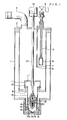
- numeral 1 denotes a heat-insulating container which has an opening at the top and a double-walled structure over the remaining part. The space between the outer and inner walls is kept to vacuum.
- numeral 2 denotes a cover member closing the opening of the container, and
- numeral 3 denotes a low-temperature liquefied gas supply conduit which is inserted into the container 1 through the cover member 2.
- Numeral 4 designates an electromagnetic check valve which is interposed between the supply conduit 3 and a low-temperature liquefied gas source (not shown), and numeral 5 designates a vaporized-gas exhaust conduit which is connected to the cover member 2 so as to communicate with the inside of the container 1 and is of a sufficient size.
- Numeral 6 designates a level sensor insertion tube inserted into the container 1 through the cover member 2, numeral 7 a level sensor provided within the level sensor insertion tube 6 which generates an output for controlling the electromagnetic check valve 4, and numeral 8 a filter provided at the end of the liquefied gas supply conduit 3.
- an opening 9 is provided in the center of the base of the inner wall of the container 1, and the top of a cylindrical member 10 is fitted into the opening 9.
- This cylindrical member 10 has an opening in the top which is closed by a cap 12 which has an aperture 11 in its side surface and another aperture 11' in its upper surface.
- An opening 13 is provided in the center of the base of the outer wall of the container 1, and the cylindrical member 10 also has a lower opening in its base. These openings are both closed by a liquefied gas outflow nozzle 14.
- the nozzle 14 has a plurality of through-holes 15 extending in the axial direction of the container 1, any desired number of which is made to open or close by a valve member 16.
- annular valve seat 17a is formed on the upper surface of the nozzle 14 at a position so as to surround the four central through-holes 15 and another annular valve seat 17b is formed so as to surround the four outer through-holes 15.
- the valve member 16 includes two valve elements corresponding to the central through-holes and the outer through-holes, respectively.
- one of the valve elements is an inner valve element 18 the lower surface of which is seated on the valve seat 17a so as to close the central through-holes 15.
- the other valve element is an outer valve element 19 which retains the inner valve element 18 slidably in the axial direction and its lower surface is seated on the valve seat 17b so as to close the outer through-holes 15.
- the valve member 16 further includes a compression spring 20 which is interposed between the upper surface of the inner valve element 18 and the upper part of the outer valve element 19 so as to force the inner valve element 18 to protrude constantly from the lower surface of the outer valve element 19; a piston rod 21 which is connected to the upper end of the outer valve element 19 and which extends upward through the cap 12 and cover member 2 in a liquid-and- air tight manner; and an elevation cylinder 22 for the piston rod 21.
- a compression spring 20 which is interposed between the upper surface of the inner valve element 18 and the upper part of the outer valve element 19 so as to force the inner valve element 18 to protrude constantly from the lower surface of the outer valve element 19
- a piston rod 21 which is connected to the upper end of the outer valve element 19 and which extends upward through the cap 12 and cover member 2 in a liquid-and- air tight manner
- an elevation cylinder 22 for the piston rod 21.
- the level of low-temperature liquefied gas in the heat-insulating container 1 is maintained constant by the operation of the electromagnetic check valve 4 which operates in response to signals from the level sensor 7. Further, the rate of flow of liquefied gas is maintained constant by the constant liquid level (head) and the constant diameter and number of through-holes 15 in the liquefied gas outflow nozzle 14.
- any vaporized-gas produced in the heat-insulating container 1 and cylindrical member 10 is exhausted directly or through the aperture 11' and the vaporized-gas exhaust conduit 5 to the outside. Accordingly, the inside pressure of the container 1 can be maintained at a constant value, atmospheric pressure, thereby ensuring good conditions for the constant flow of liquefied gas.
- One of the greatest advantages of the present invention is that not one but a plurality of through-holes 15 are formed in the nozzle 14. That is, the provision of a plurality of through-holes 15 means a reduction of the quantity of liquefied gas flowing through each through-hole 15. If the quantity of liquefied gas flow is sufficiently small, the shock of the collision of the liquefied gas against an object can be minimized sufficiently to reduce the rapid evaporation and scattering of the liquefied gas.
- the four through-holes 15 in the center of the nozzle 14 are closed by their contact with the inner valve element 18, thereby reducing the rate of flow of liquefied gas. If the piston rod 21 is lowered as far as its lowest position, the outer through-holes 15 are also closed by the outer valve element 19 in addition to the closing of the central through-holes.
- the arrangement of the through-holes 15 can be modified, for example, to be in a grid pattern of two lines of two through-holes, two lines of three through-holes, three lines of four through-holes, etc.
- the low-temperature liquefied gas outflow device of the present invention is more advantageous than prior art outflow devices of this kind in that a selected quantity of low-temperature liquefied gas can flow out accurately and constantly.
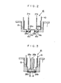
- the liquefied gas outflow nozzle 14 comprises a pair of nozzle members 14a and 14b which are positioned separately in the horizontal direction.
- the nozzle members 14a and 14b have, for example, single through-holes 15a and 15b and single annular valve seats 23a and 23b, respectively.
- a pair of valve elements 24a and 24b, provided at the lower ends of a pair of piston rods 21a and 21b are positioned to face the corresponding valve seats 23a and 23b. These valve elements 24a and 24b are made to open or close the through-holes 15a and 15b by the operation of the piston rods 21a and 21b, respectively.
- the number of through-holes 15 to be opened can be varied as required from zero to two, thereby changing the flow rate of liquefied gas as desired.
- a pair of concentric piston rods 25a and 25b are employed, having valve elements 26a and 26b, respectively at their lower ends which are arranged to be parallel.
- the number of through-holes 15 provided in the outflow nozzle 14 can be varied as desired by the operation of one or both of the piston rods 25a and 25b.
Landscapes
- Engineering & Computer Science (AREA)
- Mechanical Engineering (AREA)
- General Engineering & Computer Science (AREA)
- Filling Or Discharging Of Gas Storage Vessels (AREA)
- Vacuum Packaging (AREA)
Applications Claiming Priority (2)
| Application Number | Priority Date | Filing Date | Title |
|---|---|---|---|
| JP57067671A JPS58184396A (ja) | 1982-04-22 | 1982-04-22 | 低温液化ガス流出装置 |
| JP67671/82 | 1982-04-22 |
Publications (3)
| Publication Number | Publication Date |
|---|---|
| EP0092795A2 true EP0092795A2 (fr) | 1983-11-02 |
| EP0092795A3 EP0092795A3 (en) | 1983-12-14 |
| EP0092795B1 EP0092795B1 (fr) | 1987-03-25 |
Family
ID=13351687
Family Applications (1)
| Application Number | Title | Priority Date | Filing Date |
|---|---|---|---|
| EP83103878A Expired EP0092795B1 (fr) | 1982-04-22 | 1983-04-20 | Dispositif d'écoulement pour gaz liquéfié à basse température |
Country Status (8)
| Country | Link |
|---|---|
| US (1) | US4471627A (fr) |
| EP (1) | EP0092795B1 (fr) |
| JP (1) | JPS58184396A (fr) |
| KR (1) | KR900007255B1 (fr) |
| AU (1) | AU559283B2 (fr) |
| CA (1) | CA1205351A (fr) |
| DE (1) | DE3370526D1 (fr) |
| MX (1) | MX158968A (fr) |
Cited By (2)
| Publication number | Priority date | Publication date | Assignee | Title |
|---|---|---|---|---|
| GB2169998A (en) * | 1985-01-18 | 1986-07-23 | Metal Box Plc | Liquid nitrogen metering device with nozzle of insulating material |
| EP2569570A4 (fr) * | 2010-05-12 | 2014-08-20 | Linde Ag | Procédé de production de liquide cryogénique stérile |
Families Citing this family (6)
| Publication number | Priority date | Publication date | Assignee | Title |
|---|---|---|---|---|
| SE457750B (sv) * | 1986-07-21 | 1989-01-23 | Aga Ab | Apparat foer dosering av smaa maengder kondenserad gas |
| US4715187A (en) * | 1986-09-29 | 1987-12-29 | Vacuum Barrier Corporation | Controlled cryogenic liquid delivery |
| US4865088A (en) * | 1986-09-29 | 1989-09-12 | Vacuum Barrier Corporation | Controller cryogenic liquid delivery |
| US7628342B2 (en) * | 2004-05-11 | 2009-12-08 | Daiwa Can Company | Liquefied gas dispensing nozzle and liquefied gas dispensing apparatus |
| US7769000B2 (en) * | 2006-01-10 | 2010-08-03 | Research In Motion Limited | System and method for managing call routing in a network environment including IMS |
| US9459006B2 (en) * | 2012-05-22 | 2016-10-04 | Alstom Technology Ltd | Radial nozzle assembly for a pressure vessel |
Family Cites Families (6)
| Publication number | Priority date | Publication date | Assignee | Title |
|---|---|---|---|---|
| US2761646A (en) * | 1950-11-30 | 1956-09-04 | Thompson Prod Inc | Nozzle structure |
| US3938347A (en) * | 1974-04-12 | 1976-02-17 | Optical Coating Laboratory, Inc. | Level control apparatus and method for cryogenic liquids |
| FR2302479A1 (fr) * | 1975-02-25 | 1976-09-24 | Air Liquide | Dispositif pour la distribution controlee de fluide cryogenique |
| DE2732318C2 (de) * | 1977-07-16 | 1986-06-26 | Messer Griesheim Gmbh, 6000 Frankfurt | Vorrichtung zum Dosieren kleiner Mengen eines tiefsiedenden verflüssigten Gases |
| JPS5833439B2 (ja) * | 1980-02-05 | 1983-07-19 | 東洋製罐株式会社 | 不活性液化ガス定量滴下法および装置 |
| GB2092552B (en) * | 1980-12-17 | 1984-08-01 | Boc Ltd | Dispensing apparatus |
-
1982
- 1982-04-22 JP JP57067671A patent/JPS58184396A/ja active Granted
-
1983
- 1983-04-13 CA CA000425774A patent/CA1205351A/fr not_active Expired
- 1983-04-14 US US06/485,010 patent/US4471627A/en not_active Expired - Lifetime
- 1983-04-18 AU AU13617/83A patent/AU559283B2/en not_active Ceased
- 1983-04-20 EP EP83103878A patent/EP0092795B1/fr not_active Expired
- 1983-04-20 DE DE8383103878T patent/DE3370526D1/de not_active Expired
- 1983-04-21 MX MX197002A patent/MX158968A/es unknown
- 1983-04-21 KR KR1019830001686A patent/KR900007255B1/ko not_active Expired
Cited By (2)
| Publication number | Priority date | Publication date | Assignee | Title |
|---|---|---|---|---|
| GB2169998A (en) * | 1985-01-18 | 1986-07-23 | Metal Box Plc | Liquid nitrogen metering device with nozzle of insulating material |
| EP2569570A4 (fr) * | 2010-05-12 | 2014-08-20 | Linde Ag | Procédé de production de liquide cryogénique stérile |
Also Published As
| Publication number | Publication date |
|---|---|
| JPH0159170B2 (fr) | 1989-12-15 |
| DE3370526D1 (en) | 1987-04-30 |
| KR900007255B1 (ko) | 1990-10-06 |
| KR840004487A (ko) | 1984-10-15 |
| MX158968A (es) | 1989-04-04 |
| EP0092795B1 (fr) | 1987-03-25 |
| CA1205351A (fr) | 1986-06-03 |
| US4471627A (en) | 1984-09-18 |
| EP0092795A3 (en) | 1983-12-14 |
| JPS58184396A (ja) | 1983-10-27 |
| AU1361783A (en) | 1983-10-27 |
| AU559283B2 (en) | 1987-03-05 |
Similar Documents
| Publication | Publication Date | Title |
|---|---|---|
| US5901820A (en) | Hydraulic shock absorber | |
| US4471627A (en) | Low-temperature liquefied gas outflow device | |
| KR950003161A (ko) | 용기에 액체를 주입하는 액체주입장치 | |
| US3790139A (en) | Injector apparatus | |
| WO2002074571A3 (fr) | Soupape a vapeur de limitation de remplissage, a capacite d'event variable | |
| US4490984A (en) | Low-temperature liquefied gas constant outflow device | |
| US4579135A (en) | Valve for preventing fuel from flowing from the vent of an automobile fuel tank | |
| US3704597A (en) | Cooling apparatus | |
| EP0021202B1 (fr) | Soupape thermostatique de détente | |
| US2668396A (en) | Gas regulator | |
| US4337624A (en) | Cryostatic device | |
| JPH06288488A (ja) | 定流量弁 | |
| JPH0344517A (ja) | 高圧液体用アキュムレータ | |
| GB1456402A (en) | Sorption pumping device | |
| US2654976A (en) | Regulating valve for refrigerating installations | |
| JPS61200494A (ja) | 流量制御シンブル管 | |
| DE973488C (de) | Gaszaehler, insbesondere schiebergesteuerter Trockengaszaehler, mit eingebautem Druckregler | |
| US2278004A (en) | Pressure regulating valve | |
| US3809037A (en) | Valve for introduction of additional air into internal combustion engines | |
| JP2652487B2 (ja) | ライターの火炎の長さの自動調節装置 | |
| JPH0426722B2 (fr) | ||
| GB736711A (en) | Improvements in or relating to thermostatically controlled valves | |
| US2773664A (en) | Restrictor valve | |
| JPS6144491Y2 (fr) | ||
| US842052A (en) | Carbuter. |
Legal Events
| Date | Code | Title | Description |
|---|---|---|---|
| PUAI | Public reference made under article 153(3) epc to a published international application that has entered the european phase |
Free format text: ORIGINAL CODE: 0009012 |
|
| PUAL | Search report despatched |
Free format text: ORIGINAL CODE: 0009013 |
|
| AK | Designated contracting states |
Designated state(s): DE FR GB IT |
|
| AK | Designated contracting states |
Designated state(s): DE FR GB IT |
|
| 17P | Request for examination filed |
Effective date: 19840530 |
|
| GRAA | (expected) grant |
Free format text: ORIGINAL CODE: 0009210 |
|
| AK | Designated contracting states |
Kind code of ref document: B1 Designated state(s): DE FR GB IT |
|
| ITF | It: translation for a ep patent filed | ||
| REF | Corresponds to: |
Ref document number: 3370526 Country of ref document: DE Date of ref document: 19870430 |
|
| ET | Fr: translation filed | ||
| PLBE | No opposition filed within time limit |
Free format text: ORIGINAL CODE: 0009261 |
|
| STAA | Information on the status of an ep patent application or granted ep patent |
Free format text: STATUS: NO OPPOSITION FILED WITHIN TIME LIMIT |
|
| 26N | No opposition filed | ||
| ITTA | It: last paid annual fee | ||
| PGFP | Annual fee paid to national office [announced via postgrant information from national office to epo] |
Ref country code: GB Payment date: 19980402 Year of fee payment: 16 |
|
| PGFP | Annual fee paid to national office [announced via postgrant information from national office to epo] |
Ref country code: FR Payment date: 19980420 Year of fee payment: 16 |
|
| PGFP | Annual fee paid to national office [announced via postgrant information from national office to epo] |
Ref country code: DE Payment date: 19980528 Year of fee payment: 16 |
|
| PG25 | Lapsed in a contracting state [announced via postgrant information from national office to epo] |
Ref country code: GB Free format text: LAPSE BECAUSE OF NON-PAYMENT OF DUE FEES Effective date: 19990420 |
|
| GBPC | Gb: european patent ceased through non-payment of renewal fee |
Effective date: 19990420 |
|
| PG25 | Lapsed in a contracting state [announced via postgrant information from national office to epo] |
Ref country code: FR Free format text: LAPSE BECAUSE OF NON-PAYMENT OF DUE FEES Effective date: 19991231 |
|
| REG | Reference to a national code |
Ref country code: FR Ref legal event code: ST |
|
| PG25 | Lapsed in a contracting state [announced via postgrant information from national office to epo] |
Ref country code: DE Free format text: LAPSE BECAUSE OF NON-PAYMENT OF DUE FEES Effective date: 20000201 |