EP0092881A1 - Verfahren und Vorrichtung zum Versehen eines plastischen Rohrstückes mit einer Muffe - Google Patents
Verfahren und Vorrichtung zum Versehen eines plastischen Rohrstückes mit einer Muffe Download PDFInfo
- Publication number
- EP0092881A1 EP0092881A1 EP83200578A EP83200578A EP0092881A1 EP 0092881 A1 EP0092881 A1 EP 0092881A1 EP 83200578 A EP83200578 A EP 83200578A EP 83200578 A EP83200578 A EP 83200578A EP 0092881 A1 EP0092881 A1 EP 0092881A1
- Authority
- EP
- European Patent Office
- Prior art keywords
- plastic pipe
- pipe part
- sealing member
- mandrel
- support
- Prior art date
- Legal status (The legal status is an assumption and is not a legal conclusion. Google has not performed a legal analysis and makes no representation as to the accuracy of the status listed.)
- Granted
Links
- 238000000034 method Methods 0.000 title claims abstract description 23
- 238000007789 sealing Methods 0.000 claims abstract description 36
- 239000012530 fluid Substances 0.000 claims abstract description 15
- 230000000717 retained effect Effects 0.000 claims description 8
- 238000005452 bending Methods 0.000 description 1
- 238000005352 clarification Methods 0.000 description 1
- 230000001050 lubricating effect Effects 0.000 description 1
- 239000000463 material Substances 0.000 description 1
Images


Classifications
-
- B—PERFORMING OPERATIONS; TRANSPORTING
- B29—WORKING OF PLASTICS; WORKING OF SUBSTANCES IN A PLASTIC STATE IN GENERAL
- B29C—SHAPING OR JOINING OF PLASTICS; SHAPING OF MATERIAL IN A PLASTIC STATE, NOT OTHERWISE PROVIDED FOR; AFTER-TREATMENT OF THE SHAPED PRODUCTS, e.g. REPAIRING
- B29C49/00—Blow-moulding, i.e. blowing a preform or parison to a desired shape within a mould; Apparatus therefor
- B29C49/20—Blow-moulding, i.e. blowing a preform or parison to a desired shape within a mould; Apparatus therefor of articles having inserts or reinforcements ; Handling of inserts or reinforcements
-
- B—PERFORMING OPERATIONS; TRANSPORTING
- B29—WORKING OF PLASTICS; WORKING OF SUBSTANCES IN A PLASTIC STATE IN GENERAL
- B29C—SHAPING OR JOINING OF PLASTICS; SHAPING OF MATERIAL IN A PLASTIC STATE, NOT OTHERWISE PROVIDED FOR; AFTER-TREATMENT OF THE SHAPED PRODUCTS, e.g. REPAIRING
- B29C57/00—Shaping of tube ends, e.g. flanging, belling or closing; Apparatus therefor, e.g. collapsible mandrels
- B29C57/02—Belling or enlarging, e.g. combined with forming a groove
- B29C57/025—Belling or enlarging, e.g. combined with forming a groove combined with the introduction of a sealing ring, e.g. using the sealing element as forming element
-
- B—PERFORMING OPERATIONS; TRANSPORTING
- B29—WORKING OF PLASTICS; WORKING OF SUBSTANCES IN A PLASTIC STATE IN GENERAL
- B29C—SHAPING OR JOINING OF PLASTICS; SHAPING OF MATERIAL IN A PLASTIC STATE, NOT OTHERWISE PROVIDED FOR; AFTER-TREATMENT OF THE SHAPED PRODUCTS, e.g. REPAIRING
- B29C57/00—Shaping of tube ends, e.g. flanging, belling or closing; Apparatus therefor, e.g. collapsible mandrels
- B29C57/02—Belling or enlarging, e.g. combined with forming a groove
- B29C57/08—Belling or enlarging, e.g. combined with forming a groove using pressure difference
-
- B—PERFORMING OPERATIONS; TRANSPORTING
- B29—WORKING OF PLASTICS; WORKING OF SUBSTANCES IN A PLASTIC STATE IN GENERAL
- B29C—SHAPING OR JOINING OF PLASTICS; SHAPING OF MATERIAL IN A PLASTIC STATE, NOT OTHERWISE PROVIDED FOR; AFTER-TREATMENT OF THE SHAPED PRODUCTS, e.g. REPAIRING
- B29C49/00—Blow-moulding, i.e. blowing a preform or parison to a desired shape within a mould; Apparatus therefor
- B29C49/20—Blow-moulding, i.e. blowing a preform or parison to a desired shape within a mould; Apparatus therefor of articles having inserts or reinforcements ; Handling of inserts or reinforcements
- B29C2049/2017—Blow-moulding, i.e. blowing a preform or parison to a desired shape within a mould; Apparatus therefor of articles having inserts or reinforcements ; Handling of inserts or reinforcements outside the article
-
- Y—GENERAL TAGGING OF NEW TECHNOLOGICAL DEVELOPMENTS; GENERAL TAGGING OF CROSS-SECTIONAL TECHNOLOGIES SPANNING OVER SEVERAL SECTIONS OF THE IPC; TECHNICAL SUBJECTS COVERED BY FORMER USPC CROSS-REFERENCE ART COLLECTIONS [XRACs] AND DIGESTS
- Y10—TECHNICAL SUBJECTS COVERED BY FORMER USPC
- Y10S—TECHNICAL SUBJECTS COVERED BY FORMER USPC CROSS-REFERENCE ART COLLECTIONS [XRACs] AND DIGESTS
- Y10S425/00—Plastic article or earthenware shaping or treating: apparatus
- Y10S425/028—Impact
Definitions
- the invention relates to a method of providing a plastic pipe part with a socket end and a head part of an annular sealing member being retained in a groove chamber formed by inwardly rebending an end portion of the socket end.
- Such a method is known in the art.
- use is made of a plastic pipe part with a socket end comprising three widenings, having increasing inner diameters, the last widening being applied in the head part of a sealing sleeve and subsequently an end portion of the third widening being inwardly rebent for forming a groove chamber.
- Said known method is very advantageous as a plastic pipe part with a socket end can be obtained in a plant while the sealing member is retained in a reliable manner, the inward rebending of the endportion of the third widening around the head part of the sealing member causing the assembly to remain undamaged if the front part of the finished plastic pipe with socket end will hit the bottom under a high impact load, for instance, when such pipes are unloaded from a van.
- a disadvantage of this known method is, however, that a plastic pipe first has to be provided with three widenings and subsequently, in a later stage, with the sealing member, followed by inwardly reberding the end portion of the third widening.
- lhe present invention aims to provide a much simpler method in which an initial plastic pipe part, already provided with the required sealing member, can be used for widening said pipe part in order to form the socket end.
- the sealing member forms a seal so that a high fluid pressure can be exerted in the interior of the plastic pipe part, thus causing said plastic pipe part to obtain the shape of an outer mould surrounding said plastic pipe part and provided with walls adapted to the widenings of the socket end.
- An appropriate seal is obtained by means of the head part of the sealing member, the support preferably consisting of a mandrel.
- the widened end of a plastic pipe is very advantageously shaped by pushing the widened end part across a sealing member bearing upon a support.
- a fluid pressure is supplied to the interior of the portion of the plastic pipe part to be deformed, during the movement of the plastic pipe part across the sealing member , whereby the fluid pressure acts as a lubricating means between the plastic pipe part and the sealing member, thus providing a cup-shaped widened end in an easier manner which due to the internal fluid pressure,can subsequently easier be shaped to the desired socket end.
- the present invention in another aspect relates to apparatus for performing the method according to the invention, comprising an outer mould with three mould widenings for receiving three widenings of a socket end, a bending member for inwardly rebending an end portion of the socket end, being characterized in that the apparatus comprises a sealing member support, sealing member support retaining means,and a supply conduit for creating an internal fluid pressure in the interior of the plastic pipe part following the sealing member support.
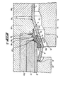
- Figure 1 illsutrates the first step in performing the method according to the invention wherein the head part 3 of a sealing sleeve 4 is placed upon a sealing member support mandrel 8.
- Said sealing sleeve further comprises sealing lips or ribs 4a, 4b, 4c, 4d and 4e, of which the lips 4d and 4e are accommodated in recesses 17.and 18 of a second mandrel 21.
- lip 4c is retained in a space 16 between a first mandrel 20 and second mandrel 21, the sealing member is retained and cannot possibly be shifted.
- an outer mould 11 comprising an inner wall 12 merging via a tapering transitional wall 13, into an inner wall 14 having a greater diameter than the portion comprising the inner wall 12, and subsequently merging into a conically widened end part 15 of the mould.
- a heated plastic pipe portion 1 is pushed across a third mandrel 30 and first mandrel 20 and subsequently across the head part 3 of a sealing member 4, so that a widened end 7 of plastic pipe portion 1 is formed, said widened end 7 merging into a likewise widened end portion 6 having a front end 9. Due to the elastic properties of the plastic material said end part 6 will try to regain its original shape beyond head part 3 of the sealing member.
- a gaseous fluid pressure is supplied through aperture 10 between the third mandrel 30 and first mandrel 20. During said deformation the fluid pressure also supports the heated and deformed portion 7.
- Figure 2 illustrates that outer mould 11 is brought into its working position whereupon a fluid of increased pressure is supplied through aperture 10.
- a fluid of increased pressure is supplied through aperture 10.
- the space 19 between support mandrel 8 and the widened end of the plastic pipe 1 is sealed by the head part 3.
- widened part 7 of the plastic pipe part will be inflated and adjoin walls 12, 13, 14 and 15 of the outer mould 11.
- first socket end widening 22 a second socket end widening 28 as well as the transitional portion 23 between pipe part 1 and the latter socket end widening 28, as well as the transitional portion 24 and the end widening 29, are cooled.
- End portion 6, however, of the widened part is not cooled.
- support mandrel 8 is removed, together with a fourth mandrel 31 disposed within the latter support mandrel 8; this situation is illustrated in fig. 3.
- rebending member 26 having a rounded inner wall 27, together with mandrel 8 and mandrel 31, are displaced into the direction of the first mandrel 20. 1he entire assembly is supported by central portion 21a of the second mandrel. 1he presence of space 25 will enable end portion 6 to be easily rebent.
- a groove chamber 5 has been formed in which the head part 3 of sealing member 4 is retained by inwardly rebent portion 6.
- first mandrel 20 is displaced into the direction of the third mandrel 30 so that lip 4c is no longer subjected to a clamping action.
- the socket end is also provided with a second socket end widening 28, in which the front end of a male pipe part is accommodated. Said second socket end widening merges into the wall of pipe part 1, through a sloping transitional part 23.
Landscapes
- Engineering & Computer Science (AREA)
- Mechanical Engineering (AREA)
- Manufacturing & Machinery (AREA)
- Shaping Of Tube Ends By Bending Or Straightening (AREA)
Priority Applications (1)
| Application Number | Priority Date | Filing Date | Title |
|---|---|---|---|
| AT83200578T ATE16573T1 (de) | 1982-04-23 | 1983-04-19 | Verfahren und vorrichtung zum versehen eines plastischen rohrstueckes mit einer muffe. |
Applications Claiming Priority (2)
| Application Number | Priority Date | Filing Date | Title |
|---|---|---|---|
| NL8201709A NL8201709A (nl) | 1982-04-23 | 1982-04-23 | Werkwijze en inrichting voor het vervaardigen van een kunststofbuisdeel met mofeinde. |
| NL8201709 | 1982-04-23 |
Publications (2)
| Publication Number | Publication Date |
|---|---|
| EP0092881A1 true EP0092881A1 (de) | 1983-11-02 |
| EP0092881B1 EP0092881B1 (de) | 1985-11-21 |
Family
ID=19839648
Family Applications (1)
| Application Number | Title | Priority Date | Filing Date |
|---|---|---|---|
| EP83200578A Expired EP0092881B1 (de) | 1982-04-23 | 1983-04-19 | Verfahren und Vorrichtung zum Versehen eines plastischen Rohrstückes mit einer Muffe |
Country Status (6)
| Country | Link |
|---|---|
| US (1) | US4474723A (de) |
| EP (1) | EP0092881B1 (de) |
| JP (1) | JPS58217314A (de) |
| AT (1) | ATE16573T1 (de) |
| DE (1) | DE3361274D1 (de) |
| NL (1) | NL8201709A (de) |
Cited By (4)
| Publication number | Priority date | Publication date | Assignee | Title |
|---|---|---|---|---|
| EP0264146A3 (en) * | 1986-10-15 | 1988-11-17 | Forsheda Ab | A method and a machine for forming an end portion of a plastic pipe |
| US6170883B1 (en) | 1998-11-06 | 2001-01-09 | Lindab Ab | Tubular element with sealing means and a method for manufacturing the tubular element |
| CN102588704A (zh) * | 2011-01-11 | 2012-07-18 | 无锡众扬金属制品有限公司 | 一种管件连接件 |
| WO2017205327A1 (en) * | 2016-05-26 | 2017-11-30 | Dow Global Technologies Llc | Mandrel and support assembly |
Families Citing this family (7)
| Publication number | Priority date | Publication date | Assignee | Title |
|---|---|---|---|---|
| US5213231A (en) * | 1981-09-18 | 1993-05-25 | Precision Valve Corporation | Aerosol container closure |
| US5024592A (en) * | 1984-05-03 | 1991-06-18 | Abplanalp Robert H | Apparatus for forming an aerosol container closure |
| SE464726B (sv) * | 1987-10-29 | 1991-06-03 | Forsheda Ab | Roermuff och saett att bilda denna |
| US6199592B1 (en) * | 1999-02-05 | 2001-03-13 | Hancor, Inc. | Pipe structure and method of manufacture |
| NL1017510C2 (nl) * | 2001-03-06 | 2002-09-20 | Wavin Bv | Inrichting en werkwijze voor het vervaardigen van een van een afdichtingsring voorzien mofeind van een buisdeel. |
| US6851165B2 (en) | 2002-09-24 | 2005-02-08 | Siemens Vdo Automotive, Inc. | Apparatus for retaining a poppet seal |
| US7314366B2 (en) * | 2005-06-17 | 2008-01-01 | Owens-Illinois Closure Inc. | Apparatus and method for inverting a stop flange on a tamper-indicating closure |
Citations (5)
| Publication number | Priority date | Publication date | Assignee | Title |
|---|---|---|---|---|
| DE2154777A1 (de) * | 1971-11-04 | 1973-05-10 | Wolfram Dr Schiemann | Vorrichtung und verfahren zum formen der wand des stutzenhalses eines extrusionsgeblasenen hohlkoerpers |
| FR2388196A1 (fr) * | 1977-04-20 | 1978-11-17 | Wavin Bv | Element de tuyau a raccord en matiere plastique et procede de fabrication de cet element |
| DE2733604A1 (de) * | 1977-07-26 | 1979-02-08 | Hms Schnallinger Industrieelek | Formkern zur herstellung von ausformungen in werkstuecken aus thermoplasten im aufblasverfahren |
| DE2738431A1 (de) * | 1977-07-29 | 1979-02-15 | Leer Verpackungen Gmbh | Vorrichtung zur herstellung einer inneren auskleidung eines gefaesses |
| NL7909296A (nl) * | 1979-12-21 | 1981-07-16 | Wavin Bv | Werkwijze en inrichting voor het vervaardigen van een buisdeel met mofeinde. |
Family Cites Families (13)
| Publication number | Priority date | Publication date | Assignee | Title |
|---|---|---|---|---|
| US3776682A (en) * | 1971-04-26 | 1973-12-04 | Rieber & Son Plastic Ind As | Apparatus for producing radially-expanded socket ends on thermoplastic pipe lengths |
| NL7209102A (de) * | 1972-06-30 | 1974-01-02 | ||
| NL178491C (nl) * | 1972-10-13 | 1986-04-01 | Polva Nederland Bv | Inrichting voor het aan het einde van een buis van thermoplastische kunststof vormen van een mof. |
| US3998578A (en) * | 1973-04-05 | 1976-12-21 | Polva-Nederland B.V. | Mandril for shaping a bell end on a pipe of thermo-plastic material |
| US4156710A (en) * | 1974-12-04 | 1979-05-29 | Phillips Petroleum Company | Fabrication of a flange adapter for plastic pipe |
| US4065243A (en) * | 1975-02-28 | 1977-12-27 | Polva Nederland B.V. | Apparatus for forming a thickened bell end on thermoplastic pipe |
| JPS5211699A (en) * | 1975-07-15 | 1977-01-28 | Matsushita Electric Works Ltd | Spring cooler head |
| JPS5245352A (en) * | 1975-10-07 | 1977-04-09 | Canon Inc | Scanning device |
| PH16346A (en) * | 1978-10-03 | 1983-09-05 | Kubota Ltd | Method of forming a socket end on a plastic pipe and a molding device for use of the method |
| EP0012480A1 (de) * | 1978-12-12 | 1980-06-25 | Polva-Nederland B.V. | Verfahren und Vorrichtung zum Formen von Kunststoff-Kupplungen |
| US4281979A (en) * | 1979-10-26 | 1981-08-04 | Owens-Illinois, Inc. | Apparatus to form a flat-topped rim on a thin-walled foam plastic container |
| US4386044A (en) * | 1979-11-09 | 1983-05-31 | Owens-Illinois, Inc. | Method of forming a cup-like container |
| FI810891L (fi) * | 1981-03-23 | 1982-09-24 | Asko Upo Oy | Foerfarande och anordning foer framstaellning av en med en taetningsring foersedd muffdel till ett plastroer |
-
1982
- 1982-04-23 NL NL8201709A patent/NL8201709A/nl not_active Application Discontinuation
-
1983
- 1983-04-19 AT AT83200578T patent/ATE16573T1/de not_active IP Right Cessation
- 1983-04-19 EP EP83200578A patent/EP0092881B1/de not_active Expired
- 1983-04-19 DE DE8383200578T patent/DE3361274D1/de not_active Expired
- 1983-04-22 US US06/487,637 patent/US4474723A/en not_active Expired - Fee Related
- 1983-04-22 JP JP58070170A patent/JPS58217314A/ja active Pending
Patent Citations (5)
| Publication number | Priority date | Publication date | Assignee | Title |
|---|---|---|---|---|
| DE2154777A1 (de) * | 1971-11-04 | 1973-05-10 | Wolfram Dr Schiemann | Vorrichtung und verfahren zum formen der wand des stutzenhalses eines extrusionsgeblasenen hohlkoerpers |
| FR2388196A1 (fr) * | 1977-04-20 | 1978-11-17 | Wavin Bv | Element de tuyau a raccord en matiere plastique et procede de fabrication de cet element |
| DE2733604A1 (de) * | 1977-07-26 | 1979-02-08 | Hms Schnallinger Industrieelek | Formkern zur herstellung von ausformungen in werkstuecken aus thermoplasten im aufblasverfahren |
| DE2738431A1 (de) * | 1977-07-29 | 1979-02-15 | Leer Verpackungen Gmbh | Vorrichtung zur herstellung einer inneren auskleidung eines gefaesses |
| NL7909296A (nl) * | 1979-12-21 | 1981-07-16 | Wavin Bv | Werkwijze en inrichting voor het vervaardigen van een buisdeel met mofeinde. |
Cited By (4)
| Publication number | Priority date | Publication date | Assignee | Title |
|---|---|---|---|---|
| EP0264146A3 (en) * | 1986-10-15 | 1988-11-17 | Forsheda Ab | A method and a machine for forming an end portion of a plastic pipe |
| US6170883B1 (en) | 1998-11-06 | 2001-01-09 | Lindab Ab | Tubular element with sealing means and a method for manufacturing the tubular element |
| CN102588704A (zh) * | 2011-01-11 | 2012-07-18 | 无锡众扬金属制品有限公司 | 一种管件连接件 |
| WO2017205327A1 (en) * | 2016-05-26 | 2017-11-30 | Dow Global Technologies Llc | Mandrel and support assembly |
Also Published As
| Publication number | Publication date |
|---|---|
| ATE16573T1 (de) | 1985-12-15 |
| EP0092881B1 (de) | 1985-11-21 |
| NL8201709A (nl) | 1983-11-16 |
| US4474723A (en) | 1984-10-02 |
| DE3361274D1 (en) | 1986-01-02 |
| JPS58217314A (ja) | 1983-12-17 |
Similar Documents
| Publication | Publication Date | Title |
|---|---|---|
| EP0092881A1 (de) | Verfahren und Vorrichtung zum Versehen eines plastischen Rohrstückes mit einer Muffe | |
| JP3325894B2 (ja) | 管連結部の形成方法並びにこの方法の実施に適切に使用される工具及び連結スリーブ | |
| US4805945A (en) | Tube joint comprising means for anchoring a sleeve at its end | |
| US4195390A (en) | Apparatus and method for manipulation and sleeving of tubular members | |
| US1647447A (en) | Method of fastening tubular bodies in holes of other bodies | |
| CA2131291A1 (en) | Method and apparatus for repairing conduits | |
| EP0725908A1 (de) | Verfahren und werkzeug zur aufweitung | |
| US4748836A (en) | Method of forming a ridge in a tube member | |
| JP2007512140A (ja) | パイプに継手を形成する方法及びその継手の製造装置 | |
| EP0761335A1 (de) | Innenhochdruckumformung und -vorrichtung | |
| US3114969A (en) | Method and structure for assembling flexible tubing within a bore, and joint produced thereby | |
| US4500485A (en) | Method for the production of a hose of a shape-cured elastomeric material, such as vulcanized rubber, especially an automotive radiator coolant hose | |
| US6044678A (en) | Method and device for manufacturing a tubular hollow body with spaced-apart increased diameter portions | |
| JPH0929362A (ja) | パイプの接続端部の成形装置及びパイプの接続端部の成形方法 | |
| US6543817B1 (en) | Process for forming radially upset tube flange and tube connector assembly formed thereby | |
| US3575033A (en) | Tubing beader | |
| US6969481B2 (en) | Method for producing a pipe termination box from thermoplastic material | |
| IE902239L (en) | Pipes with integral sockets | |
| AU2003200324A1 (en) | Method and apparatus for making a branch collar in a pipe | |
| EP0675314A1 (de) | Verfahren und Vorrichtung zum flüssigkeits- und/oder gasdichten Verbinden von wenigstens zwei Rohrelementen aus Kunststoff | |
| US3602945A (en) | Apparatus for making a plastic expansion joint | |
| ES552071A0 (es) | Un conjunto de manguito de reparacion para reparar una tuberia danada, y metodo correspondiente | |
| US7254980B2 (en) | Gas supply tube and method of making same | |
| JPH07186254A (ja) | 拡張部の形成方法とその型及びプラスチツクパイプ | |
| EP0502486B1 (de) | Methode zur Verbindung wenigstens einer Förderleitung mit dem Schalldämpfer einer Motor-Kompressoreinheit, und Motor-Kompressor |
Legal Events
| Date | Code | Title | Description |
|---|---|---|---|
| PUAI | Public reference made under article 153(3) epc to a published international application that has entered the european phase |
Free format text: ORIGINAL CODE: 0009012 |
|
| AK | Designated contracting states |
Designated state(s): AT BE CH DE FR GB IT LI LU NL SE |
|
| 17P | Request for examination filed |
Effective date: 19831018 |
|
| GRAA | (expected) grant |
Free format text: ORIGINAL CODE: 0009210 |
|
| AK | Designated contracting states |
Designated state(s): AT BE CH DE FR GB IT LI LU NL SE |
|
| PG25 | Lapsed in a contracting state [announced via postgrant information from national office to epo] |
Ref country code: NL Effective date: 19851121 Ref country code: LI Effective date: 19851121 Ref country code: IT Free format text: LAPSE BECAUSE OF FAILURE TO SUBMIT A TRANSLATION OF THE DESCRIPTION OR TO PAY THE FEE WITHIN THE PRESCRIBED TIME-LIMIT;WARNING: LAPSES OF ITALIAN PATENTS WITH EFFECTIVE DATE BEFORE 2007 MAY HAVE OCCURRED AT ANY TIME BEFORE 2007. THE CORRECT EFFECTIVE DATE MAY BE DIFFERENT FROM THE ONE RECORDED. Effective date: 19851121 Ref country code: CH Effective date: 19851121 Ref country code: BE Effective date: 19851121 |
|
| REF | Corresponds to: |
Ref document number: 16573 Country of ref document: AT Date of ref document: 19851215 Kind code of ref document: T |
|
| PG25 | Lapsed in a contracting state [announced via postgrant information from national office to epo] |
Ref country code: SE Effective date: 19851130 |
|
| REF | Corresponds to: |
Ref document number: 3361274 Country of ref document: DE Date of ref document: 19860102 |
|
| ET | Fr: translation filed | ||
| REG | Reference to a national code |
Ref country code: CH Ref legal event code: PL |
|
| NLV1 | Nl: lapsed or annulled due to failure to fulfill the requirements of art. 29p and 29m of the patents act | ||
| PG25 | Lapsed in a contracting state [announced via postgrant information from national office to epo] |
Ref country code: LU Free format text: LAPSE BECAUSE OF NON-PAYMENT OF DUE FEES Effective date: 19860430 |
|
| PLBE | No opposition filed within time limit |
Free format text: ORIGINAL CODE: 0009261 |
|
| STAA | Information on the status of an ep patent application or granted ep patent |
Free format text: STATUS: NO OPPOSITION FILED WITHIN TIME LIMIT |
|
| 26N | No opposition filed | ||
| PG25 | Lapsed in a contracting state [announced via postgrant information from national office to epo] |
Ref country code: GB Effective date: 19880419 |
|
| GBPC | Gb: european patent ceased through non-payment of renewal fee | ||
| PG25 | Lapsed in a contracting state [announced via postgrant information from national office to epo] |
Ref country code: FR Free format text: LAPSE BECAUSE OF NON-PAYMENT OF DUE FEES Effective date: 19881229 |
|
| REG | Reference to a national code |
Ref country code: FR Ref legal event code: ST |
|
| PGFP | Annual fee paid to national office [announced via postgrant information from national office to epo] |
Ref country code: AT Payment date: 19900316 Year of fee payment: 8 |
|
| PGFP | Annual fee paid to national office [announced via postgrant information from national office to epo] |
Ref country code: DE Payment date: 19900326 Year of fee payment: 8 |
|
| PG25 | Lapsed in a contracting state [announced via postgrant information from national office to epo] |
Ref country code: AT Effective date: 19910419 |
|
| PG25 | Lapsed in a contracting state [announced via postgrant information from national office to epo] |
Ref country code: DE Effective date: 19920201 |