EP0092892A1 - Construction d'amortissement de son - Google Patents
Construction d'amortissement de son Download PDFInfo
- Publication number
- EP0092892A1 EP0092892A1 EP83200596A EP83200596A EP0092892A1 EP 0092892 A1 EP0092892 A1 EP 0092892A1 EP 83200596 A EP83200596 A EP 83200596A EP 83200596 A EP83200596 A EP 83200596A EP 0092892 A1 EP0092892 A1 EP 0092892A1
- Authority
- EP
- European Patent Office
- Prior art keywords
- shaped
- box
- plate
- anyone
- shaped element
- Prior art date
- Legal status (The legal status is an assumption and is not a legal conclusion. Google has not performed a legal analysis and makes no representation as to the accuracy of the status listed.)
- Withdrawn
Links
- 230000008878 coupling Effects 0.000 claims abstract description 28
- 238000010168 coupling process Methods 0.000 claims abstract description 28
- 238000005859 coupling reaction Methods 0.000 claims abstract description 28
- 238000005192 partition Methods 0.000 claims description 9
- 230000003014 reinforcing effect Effects 0.000 claims description 3
- 239000002689 soil Substances 0.000 claims description 3
- 230000007423 decrease Effects 0.000 claims 1
- 238000010276 construction Methods 0.000 description 4
- 210000001331 nose Anatomy 0.000 description 4
- 229920003002 synthetic resin Polymers 0.000 description 2
- 239000000057 synthetic resin Substances 0.000 description 2
- 210000004233 talus Anatomy 0.000 description 2
- 238000007792 addition Methods 0.000 description 1
- 238000004873 anchoring Methods 0.000 description 1
- 230000000994 depressogenic effect Effects 0.000 description 1
- 210000000887 face Anatomy 0.000 description 1
- 210000003128 head Anatomy 0.000 description 1
- 239000000463 material Substances 0.000 description 1
- 239000002184 metal Substances 0.000 description 1
- 230000002787 reinforcement Effects 0.000 description 1
Images


Classifications
-
- E—FIXED CONSTRUCTIONS
- E01—CONSTRUCTION OF ROADS, RAILWAYS, OR BRIDGES
- E01F—ADDITIONAL WORK, SUCH AS EQUIPPING ROADS OR THE CONSTRUCTION OF PLATFORMS, HELICOPTER LANDING STAGES, SIGNS, SNOW FENCES, OR THE LIKE
- E01F8/00—Arrangements for absorbing or reflecting air-transmitted noise from road or railway traffic
- E01F8/02—Arrangements for absorbing or reflecting air-transmitted noise from road or railway traffic specially adapted for sustaining vegetation or for accommodating plants ; Embankment-type or crib-type noise barriers; Retaining walls specially adapted to absorb or reflect noise
- E01F8/021—Arrangements for absorbing or reflecting air-transmitted noise from road or railway traffic specially adapted for sustaining vegetation or for accommodating plants ; Embankment-type or crib-type noise barriers; Retaining walls specially adapted to absorb or reflect noise with integral support structure
- E01F8/023—Arrangements for absorbing or reflecting air-transmitted noise from road or railway traffic specially adapted for sustaining vegetation or for accommodating plants ; Embankment-type or crib-type noise barriers; Retaining walls specially adapted to absorb or reflect noise with integral support structure made of stacked or staggered elements, e.g. hollow
-
- E—FIXED CONSTRUCTIONS
- E02—HYDRAULIC ENGINEERING; FOUNDATIONS; SOIL SHIFTING
- E02D—FOUNDATIONS; EXCAVATIONS; EMBANKMENTS; UNDERGROUND OR UNDERWATER STRUCTURES
- E02D29/00—Independent underground or underwater structures; Retaining walls
- E02D29/02—Retaining or protecting walls
- E02D29/025—Retaining or protecting walls made up of similar modular elements stacked without mortar
Definitions
- the invention relates to a sound deadening structure comprising elements to be connected with one'another.
- the invention has for its object to provide a sound deadening structure which permits structures of varying shape and design in many ways by using a few standard components.
- the structure comprises box-shaped parts provided round about with a plurality of coupling members for connecting filling parts between the box-shaped parts.
- the filling parts can be coupled at various points with the box-shaped parts so that many variations in the development of the sound deadening structure can be obtained, as will become apparent hereinafter.
- the structure may serve as an earth retaining wall, as a reinforcement of tali or otherwise to bridge level differences or to stiffen earth bodies or the like.
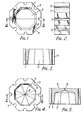
- box-shaped element shown in the accompanying drawings has an octogenal cross-section, but it will be obvious that within the spirit and scope of the invention other cross-sections of the hollow elements may be chosen, for example, circular, elliptical or other sections differing from the octogonal cross-section.
- the box-shaped element shown in Figs. 1 'to 3 is hollow and the wall 1 of the box-shaped element is the boundary wall of a central cavity 2 slightly tapering in the direction of height of the element.
- recesses 3 extend along the full height of the box-shaped element 1.
- the recesses 3 are bounded by a wall 4, which preferably constitutes an arc of a circle, in which the distance between the ends of the wall 4 is smaller than the diameter of the art concerned, which will be apparent from Fig. 1.
- the recesses 3 are also'slightly tapering.
- the height of such a box-shaped element may be 30 cms and the width may be 60 cms, although , of course, other dimensions may be used.
- Figs. 4 and 5 show a similar box-shaped element and corresponding parts are designated by the same reference numerals as in Figs. 1 to 3. In the embodiment shown in Figs. 4 and 5, however the box-shaped element is provided near the end having the smaller
- the element shown in Figs. 4 and 5 may be employed as the top element of a plurality of superposed, box-shaped elements as a terminal element. ,.
- the element shown in Figs. 4 and 5 is furthermore particularly suitable for use as a lowermost, ground-contacting element of a plurality of stfcked elements. Owing to its large surface the closing wall then bearing on the ground ensures a low surface pressure so that sinking into the ground is minimized.
- box-shaped elements may be employed in conjunction with the filling parts shown in Figs. 6 to 8 in the form of plate-shaped elements 7.From Fig. 8 it will be particularly apparent that these plate-shaped elements are constructed so that, in a sectional view, an upwardly extending boundary wall 8 is at right angles to the horizontal base wall 9, whereas the other upwardly extending boundary wall 10 is upwardly inclined from its connection with the base 9 towards the wall 8.
- the upper boundary wall 11 has a stepwise design so that on the side of the upwardly inclined sidewall 10 a protruding nose 12 is formed.
- the ends of the plate-shaped element 7 are joined by coupling members 13 having a sectional areac such that they'can be slipped into the recesses 3 of the box-shaped elements.
- the design is preferably such that when located in recesses 3 the coupling members 13 can still slightly turn about their longitudinal axes with respect to the box-shaped elements concerned.
- the centre lines 14 of the coupling members 13 are in positions such that superposed plates coupled with box-shaped elements can be alternately.disposed as is illustrated in Fig. 8. This design of the plates ensures a satisfactory, sound-deadening,junction between the plates.
- FIG. 9 A further embodiment of a plate-shaped element suitable for use in conjunction with the box-shaped elements is shown in Figs. 9 to 11.
- this plate-shaped element is formed at least mainly by a flat plate 15, the ends of which are slightly tapering. These ends have holes 16. Along a longitudinal side the plate 15 is provided with an upwardly extending nose 17.
- the coupling member 18 shown in Fig. 12 may be employed, said member being formed by a shaft 19 having a thickened central portion 20.
- the thickened central portion 20 fits in a hole 16 in the plate-shaped element, whereas the thinner parts on both sides of said thickened central portion 20 of the shaft 19 are fitting in the recesses 3.
- Fig. 13 is an elevational view of a sound deadening structure formed by stacked box-shaped elements with plate-shaped parts intermediate there between.
- An effective length of the plate-shaped parts is such that the centre-to-centre distance between successive columns of stacked box-shaped elements is about 150 cms,though, of course, other dimensions may be chosen.
- the stacked box-shaped elements may be filled with earth or concrete.
- columns of stacked box-shaped elements may be arranged side by side in the direction of length of the structure, whilst these box-shaped elements extending in the direction of length of the sound deadening structure can be coupled with plate-shaped parts 7 extending transversely of the direction of length of the structure.
- the box-shaped elements may be piled up perpendicularly one above the other or the distance between the box-shaped elements may be varied.
- the horizontal plate-shaped elements 15 or the perpendicularly stacked plate-shaped parts 7 can be arranged between the box-shaped elements in the direction of length of the sound deadening structure.
- plates 7 and 15 may be arranged between box-shaped elements as anchoring elements, is filled out with earth, this earth bearing on the horizontal, plate-shaped elements 15 will form a given talus, where plants can grow between the plate-shaped elements 15.
- the ground layer may have a given thickness up to the front side of the plates so that plants can be grown up to the front side of the plates 15.
- the noses 19 furthermore prevent the earth from being blown or flushed away due to wind or rain.
- the plate-shaped elements may be arranged in a rampart 21 of earth or the like,having a break 22.
- the head ends of the earthen rampart may be surrounded by a wall formed in the manner described above 'by the stacked, box-shaped elements and the intermediate, plate-shaped parts.
- Fig. 19 is a schematic plan view of an embodiment of the sound deadening structure, which will give a clear impression of the many variations in shape and design of the rampart obtainable by using the simple basic elements described above with reference to Figs. 1 to 12.
- the recesses 3 in the box-shaped elements may furthermore be used for accommodating the posts of frames, which is thus disposed between two relatively spaced columns of staeked box-shaped elements.
- doors, transparent or opaque screens and similar elements may be mounted with the aid of the frames in a construction erected with the aid of the elements described above.
- a so-called coupling pin half may be used, that is to say a pin having the shape of the pin shown in Fig. 12, in which the part of the shaft 19 on one side of the thickened central portion is omitted.
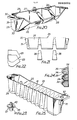
- the embodiment of the trough shown in this Figure comprises a rear wall 24, sidewalls 25 and a front wall 26.
- transverse partitions 27 For reinforcing the connection between the front wall 26 and the rear wall 24 transverse partitions 27 extending more or less parallel to the sidewalls an arranged between the front wall and the rear wall. From Fig. 20 it will be apparent that these transverse partitions are disposed in groups of two partitions near one another, whilst the space between the transverse partitions 27 is covered near the top rims of the transverse partitions 27 by stip-shaped parts 28, below which hollow spaces 29 are thus formed.
- flanges 30 extend outwardly. Below these flanges are arranged coupling members 31, which are preferably hollow and the shape of which matches the recesses 3 in the box-shaped elements 1 so that these coupling elements can be inserted into the recesses 3. The lower ends of the coupling elements 31 are in engagement with strip-shaped parts 32 transversely adjoining the sidewalls 25, which strips will also fall into a recess when a trough 23 is coupled with a box-shaped element 1.
- the troughs 23 described above can be effectively made from synthetic resin; the design may be such that they can be nested for transport purposes as is illustrated in Fig. 22.
- the sidewalls 24 When arranged as filling parts between the box-shaped elements 1 in order to obtain a sound deadening structure the sidewalls 24 will be in line with one another in vertical positions as is shown in Fig. 24.
- the design is such that the top edge of the front wall 26 is located at a lower level than the top edge of the rear wall 24 in a manner such that the line of connection between these two top edges is at an angle of about 30° to 45° to the horizontal, which more or less corresponds to the natural talus of garden soil 34 or the like to be charged into the troughs.
- plants 35 can be grown on the surface of the garden soil in the troughs so that a sound deadening structure is obtained with vegetation on at least one side.
- these cavities can be closed by means of filling pieces 36 in recesses in the rear wall 24 as is schemtaically shown in Fig. 21.
- the auxiliary pieces 37 shown in Fig. 23 are used; they are formed by a disk 38 having a thickness equal to that of the flanges 30, a coupling piece 39 protruding below the disk and fitting in the top end of a recess 3 and a coupling piece 40 protruding above the disk and fitting in the lower end of a recess 3.
- At least in some of the recesses 3 not occupied by coupling pieces 32 associated with troughs 23 are arranged in the coupling pieces 39 of the auxiliary elements 37 so that apart from the flanges 30 a few disks 38 will bear on the top sides of the box-shaped parts concerned. In this manner a satisfactory support of a box-shaped part to be disposed on the first box-shaped part is obtained at various points so that the higher box-shaped part does not tend to tilt.
- Fig. 25 shows a further embodiment of a trough to be used as a filling part. Parts. corresponding with those of the trough described above are designated by the same reference numerals as in the preceding Figures.
- the partitions 27 are omitted and the front wall and rear wall are provided with depressed parts or stiffening ridges 41.
Landscapes
- Engineering & Computer Science (AREA)
- Civil Engineering (AREA)
- Structural Engineering (AREA)
- Architecture (AREA)
- Environmental & Geological Engineering (AREA)
- Life Sciences & Earth Sciences (AREA)
- General Life Sciences & Earth Sciences (AREA)
- Mining & Mineral Resources (AREA)
- Paleontology (AREA)
- General Engineering & Computer Science (AREA)
- Building Environments (AREA)
- Devices Affording Protection Of Roads Or Walls For Sound Insulation (AREA)
Applications Claiming Priority (2)
| Application Number | Priority Date | Filing Date | Title |
|---|---|---|---|
| NL8201735 | 1982-04-27 | ||
| NL8201735A NL8201735A (nl) | 1982-04-27 | 1982-04-27 | Geluidwerende constructie. |
Publications (1)
| Publication Number | Publication Date |
|---|---|
| EP0092892A1 true EP0092892A1 (fr) | 1983-11-02 |
Family
ID=19839660
Family Applications (1)
| Application Number | Title | Priority Date | Filing Date |
|---|---|---|---|
| EP83200596A Withdrawn EP0092892A1 (fr) | 1982-04-27 | 1983-04-26 | Construction d'amortissement de son |
Country Status (2)
| Country | Link |
|---|---|
| EP (1) | EP0092892A1 (fr) |
| NL (1) | NL8201735A (fr) |
Cited By (3)
| Publication number | Priority date | Publication date | Assignee | Title |
|---|---|---|---|---|
| EP0187615A1 (fr) * | 1985-01-11 | 1986-07-16 | Rolf Scheiwiller | Jeu d'éléments pour constructions composites |
| AT387052B (de) * | 1985-09-18 | 1988-11-25 | Knoch Kern & Co | Bauelement fuer schallschutzwaende, wand aus solchen bauelementen sowie vorrichtung zur herstellung solcher bauelemente |
| EP0952260A1 (fr) * | 1998-04-22 | 1999-10-27 | Rolf Scheiwiller | Bloc en beton |
Citations (4)
| Publication number | Priority date | Publication date | Assignee | Title |
|---|---|---|---|---|
| DE7804709U1 (de) * | 1978-02-17 | 1978-07-27 | Emil Adolff Gmbh & Co Kg, 7410 Reutlingen | Schutzwand |
| FR2379650A1 (fr) * | 1977-02-02 | 1978-09-01 | Prieur Francois | Mur-talus ecran aux nuisances a base d'elements modulaires |
| FR2421243A1 (fr) * | 1978-03-31 | 1979-10-26 | Peller Et Cie Entr Albert | Mur d'isolation phonique |
| DE8005242U1 (de) * | 1980-06-04 | Reinschuetz, Hans, 7500 Karlsruhe | Bauelementesatz für eine Schallschutzwand |
-
1982
- 1982-04-27 NL NL8201735A patent/NL8201735A/nl not_active Application Discontinuation
-
1983
- 1983-04-26 EP EP83200596A patent/EP0092892A1/fr not_active Withdrawn
Patent Citations (4)
| Publication number | Priority date | Publication date | Assignee | Title |
|---|---|---|---|---|
| DE8005242U1 (de) * | 1980-06-04 | Reinschuetz, Hans, 7500 Karlsruhe | Bauelementesatz für eine Schallschutzwand | |
| FR2379650A1 (fr) * | 1977-02-02 | 1978-09-01 | Prieur Francois | Mur-talus ecran aux nuisances a base d'elements modulaires |
| DE7804709U1 (de) * | 1978-02-17 | 1978-07-27 | Emil Adolff Gmbh & Co Kg, 7410 Reutlingen | Schutzwand |
| FR2421243A1 (fr) * | 1978-03-31 | 1979-10-26 | Peller Et Cie Entr Albert | Mur d'isolation phonique |
Cited By (3)
| Publication number | Priority date | Publication date | Assignee | Title |
|---|---|---|---|---|
| EP0187615A1 (fr) * | 1985-01-11 | 1986-07-16 | Rolf Scheiwiller | Jeu d'éléments pour constructions composites |
| AT387052B (de) * | 1985-09-18 | 1988-11-25 | Knoch Kern & Co | Bauelement fuer schallschutzwaende, wand aus solchen bauelementen sowie vorrichtung zur herstellung solcher bauelemente |
| EP0952260A1 (fr) * | 1998-04-22 | 1999-10-27 | Rolf Scheiwiller | Bloc en beton |
Also Published As
| Publication number | Publication date |
|---|---|
| NL8201735A (nl) | 1983-11-16 |
Similar Documents
| Publication | Publication Date | Title |
|---|---|---|
| US4524551A (en) | Construction units for the erection of walls and method of utilization | |
| EP0171432B1 (fr) | Modules utilises pour des murs de soutenement et analogues | |
| US5252017A (en) | Setback retaining wall and concrete block and offset pin therefor | |
| US5484234A (en) | Building module for plantable walls with a bulk filling material | |
| JPH057484B2 (fr) | ||
| US4074538A (en) | Wall structures | |
| US4433944A (en) | Structural components for constructing a wall | |
| US5030035A (en) | Earth retaining system | |
| EP0181230B1 (fr) | Blocs de construction | |
| KR101331840B1 (ko) | 옹벽 축조용 식생블록 | |
| US20030140840A1 (en) | Quay wall structure | |
| KR200381301Y1 (ko) | 옹벽 축조용 조립식 블록 | |
| US3486282A (en) | Silo construction | |
| JPH0721633Y2 (ja) | 緑化擁壁構築用ブロック | |
| US4596103A (en) | Stone set for vertical wall assemblies | |
| ES1284815U (es) | Kit con placa de cultivo para plantas y placa de soporte | |
| ES2303276T3 (es) | Ladrillo moldeado. | |
| JP2001295302A (ja) | 擁壁構造及び擁壁構築工法 | |
| KR200245413Y1 (ko) | 보강토 옹벽설치용 조립식 블록 연결장치 | |
| EP4261355A1 (fr) | Panneaux pour structures de drainage | |
| KR200387351Y1 (ko) | 옹벽블럭 | |
| KR200387146Y1 (ko) | 연결식 옹벽축조용 블록 | |
| KR200391039Y1 (ko) | 조립식 옹벽의 구조 | |
| JPS6043527A (ja) | 傾斜面に於ける崩れ止め兼排水枠体用接続具 | |
| KR20060024745A (ko) | 축대옹벽블록 구조체 및 그 시공방법 |
Legal Events
| Date | Code | Title | Description |
|---|---|---|---|
| PUAI | Public reference made under article 153(3) epc to a published international application that has entered the european phase |
Free format text: ORIGINAL CODE: 0009012 |
|
| AK | Designated contracting states |
Designated state(s): AT BE CH DE FR GB IT LI LU NL SE |
|
| STAA | Information on the status of an ep patent application or granted ep patent |
Free format text: STATUS: THE APPLICATION IS DEEMED TO BE WITHDRAWN |
|
| 18D | Application deemed to be withdrawn |
Effective date: 19840703 |
|
| RIN1 | Information on inventor provided before grant (corrected) |
Inventor name: SAVELKOULS, WILHELMUS |