EP0092922A2 - Appareil d'enveloppement dans un film extensible - Google Patents
Appareil d'enveloppement dans un film extensible Download PDFInfo
- Publication number
- EP0092922A2 EP0092922A2 EP83301929A EP83301929A EP0092922A2 EP 0092922 A2 EP0092922 A2 EP 0092922A2 EP 83301929 A EP83301929 A EP 83301929A EP 83301929 A EP83301929 A EP 83301929A EP 0092922 A2 EP0092922 A2 EP 0092922A2
- Authority
- EP
- European Patent Office
- Prior art keywords
- puckering
- frame
- base
- drive
- sub
- Prior art date
- Legal status (The legal status is an assumption and is not a legal conclusion. Google has not performed a legal analysis and makes no representation as to the accuracy of the status listed.)
- Granted
Links
- 239000002985 plastic film Substances 0.000 claims abstract description 14
- 229920006255 plastic film Polymers 0.000 claims abstract description 14
- 230000003028 elevating effect Effects 0.000 claims description 8
- 238000000429 assembly Methods 0.000 claims description 6
- 230000000712 assembly Effects 0.000 claims description 6
- 238000000151 deposition Methods 0.000 claims description 3
- 239000004033 plastic Substances 0.000 description 26
- 229920003023 plastic Polymers 0.000 description 26
- 238000000034 method Methods 0.000 description 9
- 239000000463 material Substances 0.000 description 4
- 239000000155 melt Substances 0.000 description 2
- 230000001681 protective effect Effects 0.000 description 2
- 239000004809 Teflon Substances 0.000 description 1
- 229920006362 Teflon® Polymers 0.000 description 1
- 238000001816 cooling Methods 0.000 description 1
- 230000005484 gravity Effects 0.000 description 1
- 230000000977 initiatory effect Effects 0.000 description 1
- 230000014759 maintenance of location Effects 0.000 description 1
- 238000004904 shortening Methods 0.000 description 1
Images




Classifications
-
- B—PERFORMING OPERATIONS; TRANSPORTING
- B65—CONVEYING; PACKING; STORING; HANDLING THIN OR FILAMENTARY MATERIAL
- B65B—MACHINES, APPARATUS OR DEVICES FOR, OR METHODS OF, PACKAGING ARTICLES OR MATERIALS; UNPACKING
- B65B9/00—Enclosing successive articles, or quantities of material, e.g. liquids or semiliquids, in flat, folded, or tubular webs of flexible sheet material; Subdividing filled flexible tubes to form packages
- B65B9/10—Enclosing successive articles, or quantities of material, in preformed tubular webs, or in webs formed into tubes around filling nozzles, e.g. extruded tubular webs
- B65B9/13—Enclosing successive articles, or quantities of material, in preformed tubular webs, or in webs formed into tubes around filling nozzles, e.g. extruded tubular webs the preformed tubular webs being supplied in a flattened state
- B65B9/135—Enclosing successive articles, or quantities of material, in preformed tubular webs, or in webs formed into tubes around filling nozzles, e.g. extruded tubular webs the preformed tubular webs being supplied in a flattened state for palletised loads
Definitions
- This invention relates to apparatus to wrap an article or a group of articles in plastic film. There are several commercial methods each with its own apparatus for carrying out such wrapping operations.
- shrink wrapping involves the use of a tube or bag of plastic film, the bag is "set” in an expanded condition in a cooling process as the tube is manufactured. The bag is passed over the article or group of articles to be wrapped as a loose cover and it is then released from the "set” condition by the application of heat. The plastic film shrinks as a result and the articles(s) is enveloped in an elastically embracing plastic film sheath.
- the present invention overcomes the problems of both shrink wrapping and stretch wrapping outlined above and is quicker than either of the above known methods.
- the invention is primarily concerned with the apparatus to carry out the proposed wrapping method and accordingly the invention can be broadly said to comprise stretch wrapping apparatus comprising a puckering device and an expandible rectangular frame with curved corners demountably supported on the puckering device, the puckering device is for depositing a length of plastic film tube onto the expandible rectangular frame as a puckered band which band is then stretched by expanding the frame to a size sufficient to allow an article or group of articles to be stretch wrapped to pass freely through the frame and the band thereon;
- the expandible frame has a puckering plate assembly of generally U shape at each corner comprised of a puckering plate interconnected with a band support which are substantially parallel and in planes at right angles to that occupied by the expanding frame, the puckering plates lie outside the perimeter of the expanding frame and the band supports lie within the perimeter of the expanding flame, a jacking screw fixed to
- a puckering device 1 and a transporter 2 which has a puckering frame 3 mounted thereon so as to be movable from an operating position on the puckering device 1 to a use position over a load to be wrapped.
- the steps in the operation can be best seen from Fig.2 and a detailed description of the stages shown in Fig.2 will be given after a detailed description of the members 1 and 2.
- the puckering device 1 broadly comprises a base 4 housing drive means for puckering belts 5 and frame expanding drive heads 6. There is a support frame 7 for rolls of plastic film 8 in the form of a gussetted tube, which may'have transverse seal lines to convert the tube into a number of bags. The feed end of the film passes over guide means 9 so as to align it centrally over the base 4.
- the base 4 is supported on legs 10 each carrying a wheel 11 and there are guide rails 12 joining the front and rear legs 10.
- the drive means can be best seen from Figs.3 and 4 and comprise a first motor 13 coupled through a belt 14 to an idler wheel 15 fixed to a shaft 16 arranged for rotation about a vertical axis in a baring fixed to the sub-frame 26.
- a small diameter sprocket 17 fixed to the shaft 16 is engaged in a chain 18 which passes around sprockets 19 on shafts 20 (see Fig.5) to apply a drive to the belts 5 in the following manner.
- Each belt 5 is supported on two pulleys 21 and 21a fixed to shafts 22 rotatably mounted in a pair of spaced apart members 23 each supported by a pair of links 24, all of the links 24 are connected to a member 25 fixed to the sub-frame 26.
- the members 23,24 and 25 thus provide a parallel link assembly which can move backward and forward in the direction of the arrow A.
- the belt 5 and the pulley 21a are preferably of toothed form.
- the shaft 20 drives the pulley 21a through a universal joint (not shown) but indicated generally as 27, and bevel gears 28.
- a spring 29 applies a biassing force for the parallel link assembly and a stop 32 by engagement with a member 23 limits the movement of the parallel link assembly in the spring biassed direction.
- the sub-frume 26 is mounted on three jacking screws indicated 30 (see Fig.3).
- the upper ends of the screws 30 are rotatably housed in bearings 31 fixed to the sub-frame 26 with collars on the screw preventing axial movement of the screws 30 in the bearings 31.
- the lower ends of the screws are housed in threaded holes in brackets fixed to the base 4.
- the chains 18 through its engagement with the sprockets 33, rotates the jacking screws 30 to elevate the sub-frame 26 relative to the base 4 of the machine, or in the event the rotation of the motor 13 being reversed, lowers the sub-frame.
- the pitch of the threads on the jacking screws 30 and the ratio of the various sprocket sizes and the gearing between the bevel gears 28 is related so as to provide puckering characteristics to be discussed later.
- the other drive means housed in the base 4 comprises a motor 34 with a pulley 35 fixed to the drive shaft, a belt 36 connects the pulley 35 to a pulley 37 fixed to a shaft 38 mounted for rotation about a vertical axis.
- a sprocket 39 fixed to the shaft 38 is engaged by a chain 40 which passes around idlers 41 and sprockets 42 on shafts 43, which are drivingly coupled to the driving heads 6.
- the form of the driving heads 6 is a cup to receive the driven ends 44 of shafts 45 forming parts of the puckering frame assembly 3.
- the preferred drive means is by two diametrically opposed dome ended lugs in the cup to engage with two diametrically opposed dome ended lugs on the shaft 45, the shape of the lugs and small arcuate spaced occupied by them facilitates the entry of the shaft ends 44 into the cups 6.
- the puckering frame 3 is adapted to be mounted on the base 1.
- the frame 3 comprises two outer right angled tubular members 46 engaged telescopically by two like members 47, but of smaller diameter.
- the members 46 and 47 have corner mounted depending brackets comprised of two bars 48 spaced apart sufficiently to allow the belts 5 to enter therebetween.
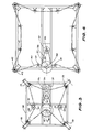
- the inner faces T of the plates 49 are teflon covered to provide minimal friction and the frame members 46 and 47 are coated, plated and/or polished for the same reason. It is to be noted that the outermost surfaces of the members 46 and 47 lie outside the planes occupied by the bars 48, see Fig.l and Fig.6.
- the plates 49 are coupled, as shown, by a ball and socket connections 51 to frame expanding screws 52 (see Fig.5) which are coupled through bevel gears 53 to the shafts 45.
- the bevel gears are housed in grearboxes 54 and the shafts 52 are housed in protective tubes 55, (see Fig.l).
- the puckering frame 3 includes a mounting frame having corner gusset plates to which the gearboxes 54 are fixed.
- the puckering frame is supported by two uprights 57 fixed to a U shaped frame 59.
- the two legs 60 of the frame 59 are end supported on wheels 61 and there are two locators 62 on the legs 50 to laterally centralise the arch frame 59 relative to the base 4 by engagement with the guides 12.
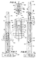
- the uprights 57 telescopically house masts which are raised and lowered as follows, see Figs.7 to 10.
- the base part 56 of the U frame 59 supports a motor 64 which, through gearing 65, drives shafts 66 rotatably supported in the base part 56.
- Sprockets 67 fixed to the shafts 66 are connected by chains 68 to sprockets 69 at the feet of the uprights 57.
- Endless chains 70 around sprockets 69a paired with the sprockets 69 pass up through the uprights 57 and around sprockets 71 at the upper end of the uprights.
- each chain 70 is fixed to an inner mast 72 as at 73 so that as the chains 70 are moved the inner mast 72 will move up or down within the uprights 57 supported at the upper and lower ends by wheel sets 74 and 75 respectively.
- the wire rope 79 is fastened at one end to the upper end of the upright 57 at 80 and passes downwardly around a pulley 81 on the inner mast 72.
- the wire rope then extends upwardly to pass around a pulley 82 at the upper end of the inner mast 72 and then downwardly where the other end of the wire rope is again fixed at 80 to the upper of the upright 57.
- the upward run of wire rope 79a passes through a hole in a plate 83 on the trolley 76 and there is a lifter block 84 fixed to the wire rope run 79a.
- the block 84 has the shape shown in Fig.9 with a pointed head 85-below which there is a reduced section portion 86 providing a shoulder 87.
- On the trolley 76 there is a pair of lever arms 88 of L shape pivoted so as to be movable as shown in Fig.9 so terminal end portions of the arms can be positioned below the head 85 and can be pivoted to a position free of the head, as shown in the enlarged fragmentary view of portion of the trolley shown in Fig.7.
- the arms are pivoted about the pivot pins 89 by a control rod 90 slidably mounted in saddle 91 on the trolley by means of pins 92 connecting the control rod 90 to the lever arms 88.
- the control rods 90 are moved in an upward direction, as the trolleys 76 descend, when the lowermost ends of the control rods 90 engage an abutment members 93 on the base 4.
- the puckering frame raising operation involves initiating the operation of the motor 64. This causes the rotation of the sprockets 69-69a which will move the chains 70 and as the inner masts 72 are fixed to the chains 73 the inner masts 72 will be raised. Movement of the inner masts 72 will cause a shortening of the wire cables below the trolleys and lengthening of the cables above the trolleys which in turn causes the blocks 84 to move to a higher elevation where they will engage under the plates 83 thereby applying a lifting force to the trolleys. This causes the puckering frame fixed to the trolleys to be raised and the shafts 45 to disengage from the heads 6. The raising of the trolleys is terminated when a desired elevation of the puckering frame has been achieved.
- the transporter can be wheeled by the handle H to a use location where the puckered plastic is placed over an object.
- Fig.2a shows the puckering frame in a working position over the puckering unit with the puckering frame released from the cables within the uprights 57 and the driven ends 44 of the shafts 45 of the gearboxes 54 located in the heads 6.
- Plastic is then unrolled from the roll 8 and the open end is located around the periphery of the puckering frame 3. The open end of the plastic is then drawn down over the puckering frame and caught between the belts 5 (which project between the bars 48) and the surfaces T of the puckering plates 49, see Fig.2b.
- the motor 13 is energised in a first direction which will cause the belts 5 to move in a downward direction, anti-clockwise as shown in Fig.5, and at the same time the jacking screws 30 wil be rotated to cause the sub-frame to be raised relative to the base 1.
- the result is a series of puckers P, as shown in Fig.5, which do not overlap.
- the rate of belt feed for puckering and the rate of sub-frame elevation is such that no overlap of puckers occurs. If overlap was to occur there would be difficulty in stripping the puckered plastic from the puckering frame.
- Puckering is continued until a predetermined amount of plastic has been placed as a puckered band on the puckering frame 3 around the bars 48 and then the plastic on the puckering frame is severed from the poll plastic 8, see Fig.2c. leaving a closed end of a plastic bag extending across the top of the puckering frame.
- Fig.2c also indicates the next operation which is to energise motor 34 to rotate the heads 6, the shafts 45 and 52 to expand the puckering frame to a predetermined size which is in excess of the cross-sectional size of the load on the pallet.
- Fig.2d indicates the transportation step which follows the raising of the puckering frame to release the ends 44 of the shafts 45 from the heads 6.
- Fig.2e indicates the puckering frame in a fully raised condition poised over a pallet and load prior to the commencement of the wrapping step.
- Fig,2f indicates to wrapping step during which the puckering frame is lowered, the plastic bag closed end over the top of the load causes the plastic to strip from the puckering frame as it descends thereby depositing the bag over the load.
- the plastic bag will commence to contract to try and achieve its unstretched condition.
- the puckering frame is lowered until the plastic bag is completely stripped from the puckering frame and the length of the bag is preferably such that the terminal end of the bag will close over the edges of the underface of the pallet.
- the pallet is preferably supported on a raised stand smaller in cross-section than the pallet.
- the puckering frame After stripping the plastic bag the puckering frame is raised and returned to its start position over the base 1.
- the controls of the puckering device and the transporter are integrated in the preferred arrangement of the invention and they are interconnected by an aerial cable extending from the top of the legs 7 to an elevated position on the transporter.
- the puckering frame can be manually delivered to a use station.
- the use of a transporter is therefore to be considered a preferred manner of handling the puckering frame and not an essntial of the apparatus of the invention.
Landscapes
- Engineering & Computer Science (AREA)
- Mechanical Engineering (AREA)
- Basic Packing Technique (AREA)
- Shaping By String And By Release Of Stress In Plastics And The Like (AREA)
- Storage Of Harvested Produce (AREA)
- Containers And Plastic Fillers For Packaging (AREA)
- Forklifts And Lifting Vehicles (AREA)
Priority Applications (1)
| Application Number | Priority Date | Filing Date | Title |
|---|---|---|---|
| AT83301929T ATE25221T1 (de) | 1982-04-23 | 1983-04-06 | Dehnfolienumwickelapparat. |
Applications Claiming Priority (2)
| Application Number | Priority Date | Filing Date | Title |
|---|---|---|---|
| AU3728/82 | 1982-04-23 | ||
| AUPF372882 | 1982-04-23 |
Publications (3)
| Publication Number | Publication Date |
|---|---|
| EP0092922A2 true EP0092922A2 (fr) | 1983-11-02 |
| EP0092922A3 EP0092922A3 (en) | 1984-08-22 |
| EP0092922B1 EP0092922B1 (fr) | 1987-01-28 |
Family
ID=3769494
Family Applications (1)
| Application Number | Title | Priority Date | Filing Date |
|---|---|---|---|
| EP83301929A Expired EP0092922B1 (fr) | 1982-04-23 | 1983-04-06 | Appareil d'enveloppement dans un film extensible |
Country Status (11)
| Country | Link |
|---|---|
| US (1) | US4546598A (fr) |
| EP (1) | EP0092922B1 (fr) |
| JP (1) | JPS58193207A (fr) |
| AT (1) | ATE25221T1 (fr) |
| AU (1) | AU553073B2 (fr) |
| BR (1) | BR8302049A (fr) |
| CA (1) | CA1220408A (fr) |
| DE (1) | DE3369493D1 (fr) |
| IE (1) | IE53949B1 (fr) |
| NZ (1) | NZ203825A (fr) |
| ZA (1) | ZA832576B (fr) |
Cited By (4)
| Publication number | Priority date | Publication date | Assignee | Title |
|---|---|---|---|---|
| GB2171976A (en) * | 1985-03-07 | 1986-09-10 | Ladislav Stephan Karpisek | A plastics sleeve stretching and dispensing device |
| AU576058B2 (en) * | 1985-03-07 | 1988-08-11 | Technosearch Pty. Limited | Wrapping equipment |
| EP0460681A1 (fr) * | 1990-06-06 | 1991-12-11 | Bernhard Beumer Maschinenfabrik KG | Installation pour plier en accordéon et/ou étirer une gaine tubulaire d'emballage étirable |
| FR2794720A1 (fr) * | 1999-06-10 | 2000-12-15 | Thimon | Procede et dispositif de mise en forme et de depose d'une housse souple thermoretractable sur une charge palettisee |
Families Citing this family (32)
| Publication number | Priority date | Publication date | Assignee | Title |
|---|---|---|---|---|
| EP0344815B2 (fr) * | 1988-06-03 | 1997-10-15 | Bernhard Beumer Maschinenfabrik KG | Procédé et dispositif pour envelopper des marchandises, en particulier des piles de marchandises avec une housse de film étirable |
| US5046302A (en) * | 1989-02-15 | 1991-09-10 | Transfresh Corporation | Method and apparatus for bagging product units |
| DE3908957C2 (de) * | 1989-03-18 | 1996-12-12 | Beumer Maschf Bernhard | Verfahren und Vorrichtung zum Umhüllen von Stückgut mit Dehnfolie (Stretchfolie) |
| US5014495A (en) * | 1990-01-31 | 1991-05-14 | Bolejack Kevin J | Method and apparatus for bagging product units |
| US5544468A (en) * | 1994-08-17 | 1996-08-13 | Preferred Packaging Systems, Inc. | Portable shipping station |
| DE19732298C1 (de) * | 1997-07-26 | 1999-02-04 | Moellers Maschf Gmbh | Vorrichtung und Verfahren zum Umhüllen eines Stapels |
| DE19819488A1 (de) * | 1998-04-30 | 1999-11-04 | Moellers Maschf Gmbh | Vorrichtung zum Umhüllen eines Stapels |
| DE20109692U1 (de) * | 2001-06-13 | 2002-10-24 | Beumer Maschinenfabrik Gmbh & Co. Kg, 59269 Beckum | Vorrichtung zum Umhüllen von Stückgut mittels einer Stretchfolienhaube |
| ES2233726T3 (es) * | 2001-06-13 | 2005-06-16 | BEUMER MASCHINENFABRIK GMBH & CO. KG | Procedimiento para la envoltura de mercancia,especialmente de pilas de mercancia, con una lamina elastica. |
| ATE296225T1 (de) * | 2001-07-11 | 2005-06-15 | Moellers Maschf Gmbh | Vorrichtung zum überziehen einer stretchfolienhaube über einen gutstapel |
| DE20205780U1 (de) * | 2002-04-10 | 2002-06-27 | Dentz, Hans, 71332 Waiblingen | Vorrichtung zum Verpacken von Gegenständen mittels Verpackungshüllen |
| EP1717148B1 (fr) * | 2002-04-19 | 2008-04-09 | Msk-Verpackungs-Systeme Gesellschaft Mit Beschränkter Haftung | Procédé pour envelopper des marchandises |
| WO2005042346A1 (fr) * | 2003-11-04 | 2005-05-12 | Roboconsult Aps | Dispositif et procede de constitution et d'emballage d'un chargement |
| DE102004063931B8 (de) * | 2004-01-08 | 2010-02-11 | Joachim Braun | Verpackungsvorrichtung zum Verpacken von Paletten |
| FR2893005A1 (fr) * | 2005-11-10 | 2007-05-11 | Thimon Sa | Procede et machine de preparation et de depose d'un manchon d'emballage sur une charge palettisee. |
| WO2007071063A1 (fr) * | 2005-12-23 | 2007-06-28 | Les Plastiques Balcan Limitée | Appareil pour ensacher un matériau |
| CA2582600C (fr) * | 2006-03-22 | 2011-08-23 | Jacques Dussault | Appareil et methode d'ensachage |
| ES2548137T3 (es) | 2008-06-05 | 2015-10-14 | Kellogg Company | Base transportadora unitaria y conformadora y un formador de bastidor deslizante para formar un contenedor transportable |
| WO2009152317A1 (fr) | 2008-06-11 | 2009-12-17 | Kellogg Company | Procédé de remplissage et de formation d'un récipient transportable pour marchandises en vrac |
| US7861500B2 (en) * | 2008-07-14 | 2011-01-04 | Bradley Arthur Bennett | Automatic cart bagger |
| EP2337741B1 (fr) * | 2008-09-03 | 2013-11-27 | Kellogg Company | Procede de formation d'un conteneur transportable pour marchandises en vrac |
| EP2336034B1 (fr) * | 2009-12-21 | 2013-01-09 | MSK - Verpackungs-Systeme GmbH | Dispositif et procédé destinés à l'enveloppement d'une pile de marchandise à l'aide d'une feuille |
| EP2377762B1 (fr) * | 2010-04-15 | 2012-08-29 | MSK - Verpackungs-Systeme GmbH | Dispositif et procédé destinés à l'enveloppement d'une pile de marchandise à l'aide d'une feuille |
| DE102010019282B4 (de) * | 2010-05-04 | 2019-06-19 | Maschinenfabrik Möllers Gmbh | Vorrichtung zum Herstellen einer Verpackungseinheit |
| WO2012075228A2 (fr) | 2010-12-01 | 2012-06-07 | Kellogg Company | Contenant transportable pour les marchandises en vrac et procédé permettant de le constituer |
| US10556721B2 (en) | 2014-03-31 | 2020-02-11 | Encore Packaging Llc | Clasp for tethering |
| US10293975B2 (en) | 2014-03-31 | 2019-05-21 | Encore Packaging Llc | Clasp for tethering |
| US20180127122A1 (en) | 2016-11-06 | 2018-05-10 | Encore Packaging Llc | Automated Box or Object Wrapping |
| USD827002S1 (en) * | 2017-03-03 | 2018-08-28 | Encore Packaging Llc | Wrapping apparatus |
| USD904477S1 (en) * | 2019-03-26 | 2020-12-08 | Rapyuta Robotics Co., Ltd. | Roll pallet opener |
| SG11202113216TA (en) * | 2019-06-10 | 2021-12-30 | Univation Tech Llc | Polyethylene blend |
| USD995589S1 (en) * | 2021-08-06 | 2023-08-15 | Robopac S.P.A. | Packaging machine |
Family Cites Families (6)
| Publication number | Priority date | Publication date | Assignee | Title |
|---|---|---|---|---|
| FR2230549A1 (en) * | 1973-05-23 | 1974-12-20 | Applic Thermiques | Machine for packing an object in a plastic sleeve - compresses sleeve into bellows form before passing object through |
| US3961459A (en) * | 1974-04-16 | 1976-06-08 | Bemis Company, Inc. | Method of and apparatus for wrapping a load in a wrapper of stretchable material |
| SE404160B (sv) * | 1974-05-11 | 1978-09-25 | Moellers Maschf | Anordning for att draga en slang av vermekrymbar plast over en godsstapel |
| US4050219A (en) * | 1976-02-19 | 1977-09-27 | Comptex, Inc. | Bagging machine |
| AU533462B2 (en) * | 1978-08-18 | 1983-11-24 | Technosearch Pty. Limited | Enclosing articles in preformed tubular webs |
| FR2473985A1 (fr) * | 1980-01-17 | 1981-07-24 | Thimon | Machine d'emballage d'une charge dans un troncon de gaine en un materiau souple |
-
1982
- 1982-04-23 AU AU13211/83A patent/AU553073B2/en not_active Ceased
-
1983
- 1983-04-06 DE DE8383301929T patent/DE3369493D1/de not_active Expired
- 1983-04-06 AT AT83301929T patent/ATE25221T1/de not_active IP Right Cessation
- 1983-04-06 IE IE786/83A patent/IE53949B1/en unknown
- 1983-04-06 EP EP83301929A patent/EP0092922B1/fr not_active Expired
- 1983-04-08 NZ NZ203825A patent/NZ203825A/en unknown
- 1983-04-11 CA CA000425625A patent/CA1220408A/fr not_active Expired
- 1983-04-13 US US06/484,476 patent/US4546598A/en not_active Expired - Fee Related
- 1983-04-13 ZA ZA832576A patent/ZA832576B/xx unknown
- 1983-04-20 BR BR8302049A patent/BR8302049A/pt unknown
- 1983-04-23 JP JP58070931A patent/JPS58193207A/ja active Pending
Cited By (5)
| Publication number | Priority date | Publication date | Assignee | Title |
|---|---|---|---|---|
| GB2171976A (en) * | 1985-03-07 | 1986-09-10 | Ladislav Stephan Karpisek | A plastics sleeve stretching and dispensing device |
| AU576058B2 (en) * | 1985-03-07 | 1988-08-11 | Technosearch Pty. Limited | Wrapping equipment |
| EP0460681A1 (fr) * | 1990-06-06 | 1991-12-11 | Bernhard Beumer Maschinenfabrik KG | Installation pour plier en accordéon et/ou étirer une gaine tubulaire d'emballage étirable |
| FR2794720A1 (fr) * | 1999-06-10 | 2000-12-15 | Thimon | Procede et dispositif de mise en forme et de depose d'une housse souple thermoretractable sur une charge palettisee |
| EP1060988A1 (fr) | 1999-06-10 | 2000-12-20 | Thimon S.A. | Procédé et dispositif de mise en forme et de dépose d'une housse souple thermorétractable sur une charge palettisée |
Also Published As
| Publication number | Publication date |
|---|---|
| CA1220408A (fr) | 1987-04-14 |
| AU1321183A (en) | 1983-10-27 |
| BR8302049A (pt) | 1983-12-27 |
| US4546598A (en) | 1985-10-15 |
| ATE25221T1 (de) | 1987-02-15 |
| AU553073B2 (en) | 1986-07-03 |
| IE830786L (en) | 1983-10-23 |
| JPS58193207A (ja) | 1983-11-10 |
| ZA832576B (en) | 1984-01-25 |
| EP0092922A3 (en) | 1984-08-22 |
| EP0092922B1 (fr) | 1987-01-28 |
| IE53949B1 (en) | 1989-04-26 |
| NZ203825A (en) | 1985-09-13 |
| DE3369493D1 (en) | 1987-03-05 |
Similar Documents
| Publication | Publication Date | Title |
|---|---|---|
| US4546598A (en) | Stretch wrapping apparatus | |
| US4747252A (en) | Material positioning and securing apparatus and process | |
| EP0294339A2 (fr) | Une machine pour l'emballage de plusieurs types d'articles dans un film plastique étirable | |
| US6161365A (en) | Method for hermetically bagging material, e.g. lumber pieces, in a tubular plastic tube | |
| JPH03611A (ja) | 束ねられた容器等を連続して包装する方法及び装置 | |
| CN110902577B (zh) | 一种袋装肥料摆放用排板装置 | |
| CN112319902A (zh) | 一种自动化高效水果套网装置及其方法 | |
| JPH0517126B2 (fr) | ||
| KR930011364B1 (ko) | 적재물의 포장장치 | |
| US4721503A (en) | Agricultural storage bag folding apparatus and method | |
| CN119037848B (zh) | 挂绳包装生产线 | |
| CN222572603U (zh) | 夹取组件、抓料机构、接线盒扎带装置及接线盒绕线扎带设备 | |
| EP0399046A1 (fr) | Appareil d'emballage pour enroulement d'un film tendu au prealable | |
| CN214690619U (zh) | 一种全自动除膜机 | |
| CN216916528U (zh) | 一种三角带成品装袋辅助装置 | |
| CN212268632U (zh) | 一种物料供料装置 | |
| CN223356102U (zh) | 一种缠绕膜打包机 | |
| CN210312327U (zh) | 一种皮带包覆旋转装置 | |
| CN221543699U (zh) | 一种内撑件包装分离机 | |
| CN113928629A (zh) | 一种电器线束组件及其捆扎加工生产工艺 | |
| CN214732197U (zh) | 一种电线电缆成品缠绕包装输送装置 | |
| CN119190495B (zh) | 一种可生物降解的胶带缠绕设备及缠绕方法 | |
| CN217533334U (zh) | 一种卧式包装膜缠绕属具 | |
| CN218432570U (zh) | 一链轮生产用搬运装置 | |
| CN212355605U (zh) | 一种可通风的拉伸膜加工用成品膜存贮装置 |
Legal Events
| Date | Code | Title | Description |
|---|---|---|---|
| PUAI | Public reference made under article 153(3) epc to a published international application that has entered the european phase |
Free format text: ORIGINAL CODE: 0009012 |
|
| AK | Designated contracting states |
Designated state(s): AT BE CH DE FR GB IT LI LU NL SE |
|
| PUAL | Search report despatched |
Free format text: ORIGINAL CODE: 0009013 |
|
| AK | Designated contracting states |
Designated state(s): AT BE CH DE FR GB IT LI LU NL SE |
|
| 17P | Request for examination filed |
Effective date: 19850129 |
|
| GRAA | (expected) grant |
Free format text: ORIGINAL CODE: 0009210 |
|
| AK | Designated contracting states |
Kind code of ref document: B1 Designated state(s): AT BE CH DE FR GB IT LI LU NL SE |
|
| REF | Corresponds to: |
Ref document number: 25221 Country of ref document: AT Date of ref document: 19870215 Kind code of ref document: T |
|
| ET | Fr: translation filed | ||
| REF | Corresponds to: |
Ref document number: 3369493 Country of ref document: DE Date of ref document: 19870305 |
|
| ITF | It: translation for a ep patent filed | ||
| PG25 | Lapsed in a contracting state [announced via postgrant information from national office to epo] |
Ref country code: LU Free format text: LAPSE BECAUSE OF NON-PAYMENT OF DUE FEES Effective date: 19870430 |
|
| PGFP | Annual fee paid to national office [announced via postgrant information from national office to epo] |
Ref country code: NL Payment date: 19870430 Year of fee payment: 5 |
|
| PLBE | No opposition filed within time limit |
Free format text: ORIGINAL CODE: 0009261 |
|
| STAA | Information on the status of an ep patent application or granted ep patent |
Free format text: STATUS: NO OPPOSITION FILED WITHIN TIME LIMIT |
|
| 26N | No opposition filed | ||
| PG25 | Lapsed in a contracting state [announced via postgrant information from national office to epo] |
Ref country code: AT Effective date: 19880406 |
|
| PG25 | Lapsed in a contracting state [announced via postgrant information from national office to epo] |
Ref country code: LI Effective date: 19880430 Ref country code: CH Effective date: 19880430 |
|
| BERE | Be: lapsed |
Owner name: KARPISEK LADISLAV STEPHAN Effective date: 19880430 |
|
| PG25 | Lapsed in a contracting state [announced via postgrant information from national office to epo] |
Ref country code: NL Effective date: 19881101 |
|
| NLV4 | Nl: lapsed or anulled due to non-payment of the annual fee | ||
| REG | Reference to a national code |
Ref country code: CH Ref legal event code: PL |
|
| PG25 | Lapsed in a contracting state [announced via postgrant information from national office to epo] |
Ref country code: BE Effective date: 19890430 |
|
| PGFP | Annual fee paid to national office [announced via postgrant information from national office to epo] |
Ref country code: SE Payment date: 19900427 Year of fee payment: 8 |
|
| PG25 | Lapsed in a contracting state [announced via postgrant information from national office to epo] |
Ref country code: SE Effective date: 19910407 |
|
| PGFP | Annual fee paid to national office [announced via postgrant information from national office to epo] |
Ref country code: FR Payment date: 19910409 Year of fee payment: 9 |
|
| PGFP | Annual fee paid to national office [announced via postgrant information from national office to epo] |
Ref country code: DE Payment date: 19910430 Year of fee payment: 9 |
|
| PG25 | Lapsed in a contracting state [announced via postgrant information from national office to epo] |
Ref country code: FR Effective date: 19921230 |
|
| PG25 | Lapsed in a contracting state [announced via postgrant information from national office to epo] |
Ref country code: DE Effective date: 19930101 |
|
| REG | Reference to a national code |
Ref country code: FR Ref legal event code: ST |
|
| PGFP | Annual fee paid to national office [announced via postgrant information from national office to epo] |
Ref country code: GB Payment date: 19930406 Year of fee payment: 11 |
|
| PG25 | Lapsed in a contracting state [announced via postgrant information from national office to epo] |
Ref country code: GB Effective date: 19940406 |
|
| GBPC | Gb: european patent ceased through non-payment of renewal fee |
Effective date: 19940406 |
|
| EUG | Se: european patent has lapsed |
Ref document number: 83301929.2 Effective date: 19911108 |