EP0093176A1 - Structure de disque d'embrayage - Google Patents
Structure de disque d'embrayage Download PDFInfo
- Publication number
- EP0093176A1 EP0093176A1 EP82903188A EP82903188A EP0093176A1 EP 0093176 A1 EP0093176 A1 EP 0093176A1 EP 82903188 A EP82903188 A EP 82903188A EP 82903188 A EP82903188 A EP 82903188A EP 0093176 A1 EP0093176 A1 EP 0093176A1
- Authority
- EP
- European Patent Office
- Prior art keywords
- hub
- plate
- disc
- torque
- friction
- Prior art date
- Legal status (The legal status is an assumption and is not a legal conclusion. Google has not performed a legal analysis and makes no representation as to the accuracy of the status listed.)
- Granted
Links
Images


Classifications
-
- F—MECHANICAL ENGINEERING; LIGHTING; HEATING; WEAPONS; BLASTING
- F16—ENGINEERING ELEMENTS AND UNITS; GENERAL MEASURES FOR PRODUCING AND MAINTAINING EFFECTIVE FUNCTIONING OF MACHINES OR INSTALLATIONS; THERMAL INSULATION IN GENERAL
- F16F—SPRINGS; SHOCK-ABSORBERS; MEANS FOR DAMPING VIBRATION
- F16F15/00—Suppression of vibrations in systems; Means or arrangements for avoiding or reducing out-of-balance forces, e.g. due to motion
- F16F15/10—Suppression of vibrations in rotating systems by making use of members moving with the system
- F16F15/12—Suppression of vibrations in rotating systems by making use of members moving with the system using elastic members or friction-damping members, e.g. between a rotating shaft and a gyratory mass mounted thereon
- F16F15/121—Suppression of vibrations in rotating systems by making use of members moving with the system using elastic members or friction-damping members, e.g. between a rotating shaft and a gyratory mass mounted thereon using springs as elastic members, e.g. metallic springs
- F16F15/123—Wound springs
- F16F15/12353—Combinations of dampers, e.g. with multiple plates, multiple spring sets, i.e. complex configurations
- F16F15/1236—Combinations of dampers, e.g. with multiple plates, multiple spring sets, i.e. complex configurations resulting in a staged spring characteristic, e.g. with multiple intermediate plates
- F16F15/12366—Combinations of dampers, e.g. with multiple plates, multiple spring sets, i.e. complex configurations resulting in a staged spring characteristic, e.g. with multiple intermediate plates acting on multiple sets of springs
Definitions
- This invention relates to the structure of a clutch disc in a clutch apparatus for an automobile, which is constructed for absorbing a torque variation occurring during idling.
- rattling meshing noise is generated from the gears of the transmission due to non-uniform rotation of the engine especially when the engine is idling, that is, when the gears of the transmission are placed in a no-loaded condition.
- the present invention provides a clutch disc structure in which the surface pressure at the sliding surfaces of a hub plate of a hub splined to an output shaft connected to a transmission and a disc plate is reduced so as to prevent generation of noise during idling, and a bush is press-fitted between the disc plate and the hub so as to prevent intrusion of dust into the sliding surfaces, thereby preventing generation of noise.
- the present invention provides a clutch disc structure in which the surface pressure at the sliding surfaces of a hub plate of a hub splined to an output shaft connected to a transmission and a disc plate is reduced so as to prevent generation of noise during idling, a bush is press-fitted between the sliding surfaces of the disc plate and the hub to be located on at least one side of such surfaces so as to prevent intrusion of dust into the sliding surfaces, and the hub, the bush, and a friction member interposed between the hub plate and a friction plate are plated with satisfactory wear-resistive coatings thereby preventing generation of noise from the individual members.
- the present invention provides a clutch apparatus in which, in order to prevent generation of noise during idling and in order that a torsion spring and a sub-torsion spring may not abut and interfere with a friction plate held between the disc plate and the hub plate spring-retaining lugs are formed integrally with the spring holding portions of the hub plate, thereby preventing generation of noise.
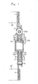
- FIG. 1 to FIG. 4 show the structure of the clutch disc according to the present invention.
- 1 designates friction discs
- 2 designates disc plates fixed to the friction discs 1
- 3 designates a hub splined to an output shaft connected to a transmission (not shown)
- 4 designates a hub plate having four projections extending radially from the hub 3.
- 5 designates a torque plate disposed on the outer diametral side of the hub plate 4 to transmit the torque from the disc plates 2 to the hub 3 through the hub plate 4
- 6 designates stop pins fixing the ends of the disc plates 2 and inserted in grooves formed in the torque plate 5
- 7 and 8 designate a pair of torque springs and a pair of sub-torque springs respectively disposed between the disc plates 2 and the torque plate 5.
- a play having a clearance ⁇ is provided between said pair of the sub-torque springs 8 and the torque plate 5.
- 11a and 11b designate pairs of friction members respectively.
- the former are disposed between the disc plates 2 and the friction plates 9 and are made of a material having a high coefficient of friction, and the latter are disposed between the friction plates 9 and the hub plate 4 and are made of a material having a low coefficient of friction, so as to control the fine adjustment of torque variation when the clutch is engaged.
- 12 and 13 designate a torsion spring disposed between the friction plates 9 and the hub plate 4 and a sub-torsion spring disposed between the friction plates 9 and the hub plate 4, with a play having a clearance r, respectively.
- the torque transmission from the engine is arranged to be transmitted along the system shown in FIG. 1.
- a bush 14 is press-fitted between the sliding surface of the disc plates 2 and hub 3 to be located on at least one side of such surfaces for reducing the surface pressure. As shown in FIG. 3, the bush 14 is formed at its inner peripheral portion with a grease groove 14a for reducing friction with the hub 3.
- a flange 2a is formed on the side of the disc plates 2 remote from the side where the bush 14 is press-fitted, for reducing the surface pressure between the disc plates 2 and the hub 3 and also for preventing intrusion of dust from the exterior.
- the structure may be such that the bush 14 is press-fitted on both sides of the disc plates 2.
- predetermined plated coatings are provided on the hub 3, friction members 1 1a, 11b and bush 14 for improving the resistance to wear.
- an electroless plated Ni coating is provided on the hub 3. It is preferable that the thickness is about 3 - 11 ⁇ , and the plated coating hardness is about Hmv 600 - 1,000.
- a plated teflon-nickel composite coating 14c having a thickness of about 10 - 16 ⁇ and a plated coating hardness of about Hmv 450 - 550 is provided on the Fe base 14b of the bush 14.
- the firction member 11a and 11b are also similarly plated with a composite coating of teflon-nickel.
- the plated composite coating has a low coefficient of friction depending on the content of teflon, and wear is remarkably little when it is combined with the members above described. Most excellent results from the aspect of maintainability of the low coefficient of friction were obtained when the content of teflon was selected to be 9 i 2% (per volume) with the remainder being Ni and the grain size of teflon was selected to be 0.3 - 1 ⁇ .
- spring-retaining lugs 4a are formed integrally with the spring holding portions of the hub plate 4 as shown in FIGs. 4 (a), 4 (b) so that the both ends of these springs may not be lodged or displaced toward the friction plates 9.
- the torque from the engine is transmitted to the torque springs 7 through the friction discs 1 and disc plates 2, and, without deflecting the torque springs 7, the torque is transmitted to the torsion spring 12 through the torque plate 5 and friction plates 9. Consequently, the torsion spring 12 is not appreciably deflected, and the torque is transmitted through the hub plate 4 to the hub 3 to be transmitted to the transmission.
- the friction members 11a and 11b act to ensure smooth operation of the torque springs 7, torsion spring 12 and sub-torsion spring 13.
- the sub-torsion spring 13 is deflected beyond the clearance r , and, under the condition in which the torque plate 5 and the hub plate 4 are unitarily coupled together, the torque springs 7 are deflected by the amount corresponding to the clearance 0 of the sub-torque springs 8 to transmit the torque to the hub 3.
- the bush 14 is interposed between the sliding surfaces of the disc plates 2 and the hub 3, the surface pressure is small, and the predetermined plating applied to the individual members having the sliding surfaces improves the resistance to wear.
- the clutch disc according to the present invention has such a structure that a bush is press-fitted between the sliding surfaces of the hub and the disc plates and thus exhibits very marked practical effects among others that the surface pressure at the sliding surfaces can be reduced, and intrusion of dust into the sliding surfaces can be prevented.
- the bush is press-fitted between the sliding surfaces of the hub and the disc plates so as to reduce the surface pressure at the sliding surfaces, and, also, the individual members having the sliding surfaces are plated so as to decrease the coefficient of friction thereby remarkably improving the wear resistance of the individual members providing the sliding surfaces. Therefore, the present invention exhibits very marked practical effects among others that the noise and vibration can be reduced.
- a torque plate engageable with the hub plate is disposed on the outer diametral side of the hub of the transmission output shaft, and a sub-torsion spring is mounted with a play between said hub plate and the torque plate so as to absorb a torque variation occurring when the clutch is turned ON from the engine idling condition. Therefore, the present invention exhibits such effects among others that generation of collision noise between the hub plate and the torque plate can be prevented and, also, generation of rattling meshing noise in the transmission can be prevented.
- the torsion spring disposed between the friction plates and the hub plate and the sub-torsion spring similarly disposed therebetween with a clearance are retained in position by being positioned at their both ends by the spring-retaining lugs formed on the spring holding portions of the hub plate, so that these springs may not interfere with the friction plates due to lodging or displacement of the springs attributable to a torque variation not only during idling but also during clutch engagement. Therefore, the present invention exhibits very marked practical effects among others that generation of hysteresis torque can be suppressed, and generation of noise can also be prevented.
Landscapes
- Engineering & Computer Science (AREA)
- General Engineering & Computer Science (AREA)
- Physics & Mathematics (AREA)
- Acoustics & Sound (AREA)
- Aviation & Aerospace Engineering (AREA)
- Mechanical Engineering (AREA)
- Mechanical Operated Clutches (AREA)
Abstract
Applications Claiming Priority (6)
| Application Number | Priority Date | Filing Date | Title |
|---|---|---|---|
| JP161632/81U | 1981-10-29 | ||
| JP161631/81U | 1981-10-29 | ||
| JP16163181U JPS5867122U (ja) | 1981-10-29 | 1981-10-29 | クラツチデイスクの構造 |
| JP16163281U JPS5867123U (ja) | 1981-10-29 | 1981-10-29 | クラツチデイスクの構造 |
| JP16163381U JPS5867124U (ja) | 1981-10-29 | 1981-10-29 | クラツチデイスクの構造 |
| JP161633/81U | 1981-10-29 |
Publications (3)
| Publication Number | Publication Date |
|---|---|
| EP0093176A1 true EP0093176A1 (fr) | 1983-11-09 |
| EP0093176A4 EP0093176A4 (fr) | 1984-04-06 |
| EP0093176B1 EP0093176B1 (fr) | 1987-01-21 |
Family
ID=27321895
Family Applications (1)
| Application Number | Title | Priority Date | Filing Date |
|---|---|---|---|
| EP82903188A Expired EP0093176B1 (fr) | 1981-10-29 | 1982-10-29 | Structure de disque d'embrayage |
Country Status (5)
| Country | Link |
|---|---|
| US (1) | US4560054A (fr) |
| EP (1) | EP0093176B1 (fr) |
| AU (1) | AU546271B2 (fr) |
| DE (1) | DE3275224D1 (fr) |
| WO (1) | WO1983001663A1 (fr) |
Cited By (10)
| Publication number | Priority date | Publication date | Assignee | Title |
|---|---|---|---|---|
| DE3810922A1 (de) * | 1987-04-07 | 1988-10-27 | Valeo | Torsionsschwingungsdaempfer, insbesondere reibscheibe fuer ein kraftfahrzeug |
| FR2626641A1 (fr) * | 1988-01-29 | 1989-08-04 | Luk Lamellen & Kupplungsbau | Volant de compensation des a-coups de moteurs a combustion interne |
| DE4090690T1 (de) * | 1989-05-02 | 1991-04-25 | Daikin Mfg Co Ltd | Daempfungsscheibe |
| FR2670852A1 (fr) * | 1990-12-19 | 1992-06-26 | Fichtel & Sachs Ag | Disque d'embrayage pour un embrayage a friction d'un vehicule automobile. |
| GB2287302A (en) * | 1994-03-09 | 1995-09-13 | Fichtel & Sachs Ag | A clutch plate having a torsional vibration damper |
| US5617939A (en) * | 1994-08-23 | 1997-04-08 | Fichtel & Sachs Ag | Friction clutch assembly for a motor vehicle, the friction clutch assembly having a clutch plate with divided hub disc |
| GB2306619A (en) * | 1995-10-20 | 1997-05-07 | Exedy Corp | Damper disc assembly and friction coupling device for clutch |
| FR2750751A1 (fr) * | 1996-07-03 | 1998-01-09 | Exedy Corp | Ensemble formant disque amortisseur |
| DE3844987C2 (de) * | 1987-04-07 | 1998-06-25 | Valeo | Torsionsdämpfer, insbesondere Reibscheibe für ein Kraftfahrzeug |
| DE4090690C2 (de) * | 1989-05-02 | 1999-04-29 | Exedy Corp | Dämpfungsscheibe |
Families Citing this family (24)
| Publication number | Priority date | Publication date | Assignee | Title |
|---|---|---|---|---|
| US4745817A (en) * | 1981-08-05 | 1988-05-24 | Honda Giken Kogyo Kabushiki Kaisha | Piston/crank connection mechanism for an internal combustion engine |
| GB2154704B (en) * | 1983-08-10 | 1986-11-19 | Mitsubishi Motors Corp | Spring-type clutch disk |
| DE3407524A1 (de) * | 1984-03-01 | 1985-09-05 | Fichtel & Sachs Ag, 8720 Schweinfurt | Torsionsschwingungsdaempfer mit weichem uebergang zwischen zwei federsystemen |
| DE3515928C2 (de) * | 1985-05-03 | 1994-04-14 | Fichtel & Sachs Ag | Geteiltes Schwungrad für eine Brennkraftmaschine |
| JPH0612262Y2 (ja) * | 1985-08-20 | 1994-03-30 | アイシン精機株式会社 | トルク変動吸収装置 |
| FR2591690B1 (fr) * | 1985-12-13 | 1991-12-06 | Luk Lamellen & Kupplungsbau | Corps discoide, tel que disque d'embrayage pour vehicule |
| FR2633360B1 (fr) * | 1988-06-22 | 1993-01-08 | Valeo | Dispositif amortisseur de torsion, notamment pour vehicule automobile |
| JPH028533A (ja) * | 1988-06-24 | 1990-01-12 | Daikin Mfg Co Ltd | ダンパーディスク |
| DE68906496T2 (de) * | 1988-09-28 | 1993-10-28 | Toyota Motor Co Ltd | Schwungradvorrichtung mit Torsionsdämpfer. |
| FR2646487B1 (fr) * | 1989-04-28 | 1994-04-22 | Valeo | Dispositif amortisseur de torsion a amortisseur dynamique de vibrations, notamment pour vehicules automobiles |
| US5161660A (en) * | 1990-11-15 | 1992-11-10 | Luk Lamellen Und Kupplungsbau Gmbh | Clutch plate with plural dampers |
| US5246399A (en) * | 1991-12-11 | 1993-09-21 | Borg-Warner Automotive Transmission & Engine Components Corporation | Two-stage torsional vibration damper |
| JP3262241B2 (ja) * | 1993-09-07 | 2002-03-04 | ヴァレオユニシアトランスミッション株式会社 | トーショナルダンパの振動減衰装置 |
| KR950008208A (ko) * | 1993-09-23 | 1995-04-17 | 그레그 지질레워스키 | 비틀림 댐퍼 |
| JPH11303890A (ja) | 1998-04-17 | 1999-11-02 | Exedy Corp | プレート及びダンパーディスク組立体 |
| JPH11303939A (ja) * | 1998-04-17 | 1999-11-02 | Exedy Corp | ダンパーディスク組立体 |
| JPH11303891A (ja) | 1998-04-17 | 1999-11-02 | Exedy Corp | プレート及びダンパーディスク組立体 |
| JPH11303892A (ja) | 1998-04-17 | 1999-11-02 | Exedy Corp | ダンパーディスク組立体 |
| JP2000002263A (ja) | 1998-06-16 | 2000-01-07 | Exedy Corp | ブッシュ |
| JP3619372B2 (ja) | 1998-09-01 | 2005-02-09 | 株式会社エクセディ | ダンパーディスク組立体 |
| JP3732021B2 (ja) | 1998-09-18 | 2006-01-05 | 株式会社エクセディ | ダンパー機構 |
| JP2000179572A (ja) | 1998-12-18 | 2000-06-27 | Exedy Corp | ダンパーディスク組立体 |
| KR101028014B1 (ko) * | 2008-10-31 | 2011-04-13 | 현대자동차일본기술연구소 | 하이브리드 차량의 클러치 전달토크 제어 방법 |
| WO2014203309A1 (fr) * | 2013-06-17 | 2014-12-24 | 株式会社小松製作所 | Niveleuse motorisée |
Family Cites Families (13)
| Publication number | Priority date | Publication date | Assignee | Title |
|---|---|---|---|---|
| GB512009A (en) * | 1938-02-25 | 1939-08-28 | Noel Banner Newton | Improvements in or relating to clutch plates |
| US3138039A (en) * | 1962-08-17 | 1964-06-23 | Borg Warner | Vibration damper assembly |
| JPS4626487Y1 (fr) * | 1968-10-22 | 1971-09-11 | ||
| DE2315946C3 (de) * | 1973-03-30 | 1984-03-22 | LuK Lamellen und Kupplungsbau GmbH, 7580 Bühl | Kupplungsscheibe |
| DE2356559C2 (de) * | 1973-11-13 | 1975-06-05 | Daimler-Benz Ag, 7000 Stuttgart | Kupplungsscheibe für Kraftfahrzeug-Hauptkupplungen |
| DE2430160C2 (de) * | 1974-06-24 | 1975-09-25 | Daimler-Benz Ag, 7000 Stuttgart | Kupplungsscheibe für Kraftfahrzeug-Hauptkupplungen |
| JPS5519314Y2 (fr) * | 1975-09-18 | 1980-05-08 | ||
| FR2386729A1 (fr) * | 1977-04-04 | 1978-11-03 | Ferodo Sa | Dispositif amortisseur de torsion, en particulier friction d'embrayage, notamment pour vehicule automobile |
| JPS5531075U (fr) * | 1978-08-21 | 1980-02-28 | ||
| GB2052683B (en) * | 1979-06-07 | 1983-01-26 | Automotive Prod Co Ltd | Friction clutch driven plate |
| JPS56167919A (en) * | 1980-05-23 | 1981-12-23 | Mazda Motor Corp | Clutch disk |
| FR2503295B1 (fr) * | 1981-04-01 | 1988-04-15 | Automotive Prod France | Disque de sortie d'embrayage a friction |
| US4471863A (en) * | 1981-08-28 | 1984-09-18 | Borg-Warner Corporation | Multi-stage torsional damping device |
-
1982
- 1982-10-29 EP EP82903188A patent/EP0093176B1/fr not_active Expired
- 1982-10-29 AU AU90554/82A patent/AU546271B2/en not_active Ceased
- 1982-10-29 DE DE8282903188T patent/DE3275224D1/de not_active Expired
- 1982-10-29 WO PCT/JP1982/000424 patent/WO1983001663A1/fr not_active Ceased
- 1982-10-29 US US06/514,801 patent/US4560054A/en not_active Expired - Lifetime
Cited By (19)
| Publication number | Priority date | Publication date | Assignee | Title |
|---|---|---|---|---|
| DE3844987C2 (de) * | 1987-04-07 | 1998-06-25 | Valeo | Torsionsdämpfer, insbesondere Reibscheibe für ein Kraftfahrzeug |
| DE3810922C2 (de) * | 1987-04-07 | 1998-07-23 | Valeo | Torsionsschwingungsdämpfer, insbesondere Reibscheibe für ein Kraftfahrzeug |
| DE3810922A1 (de) * | 1987-04-07 | 1988-10-27 | Valeo | Torsionsschwingungsdaempfer, insbesondere reibscheibe fuer ein kraftfahrzeug |
| FR2626641A1 (fr) * | 1988-01-29 | 1989-08-04 | Luk Lamellen & Kupplungsbau | Volant de compensation des a-coups de moteurs a combustion interne |
| GB2214610A (en) * | 1988-01-29 | 1989-09-06 | Luk Lamellen & Kupplungsbau | Flywheel |
| GB2214610B (en) * | 1988-01-29 | 1991-09-25 | Luk Lamellen & Kupplungsbau | Flywheel |
| DE4090690T1 (de) * | 1989-05-02 | 1991-04-25 | Daikin Mfg Co Ltd | Daempfungsscheibe |
| DE4090690C2 (de) * | 1989-05-02 | 1999-04-29 | Exedy Corp | Dämpfungsscheibe |
| FR2670852A1 (fr) * | 1990-12-19 | 1992-06-26 | Fichtel & Sachs Ag | Disque d'embrayage pour un embrayage a friction d'un vehicule automobile. |
| US5588518A (en) * | 1994-03-09 | 1996-12-31 | Fichtel & Sachs Ag | Clutch disc with a reinforced hub |
| GB2287302B (en) * | 1994-03-09 | 1998-04-15 | Fichtel & Sachs Ag | Clutch plate |
| FR2717232A1 (fr) * | 1994-03-09 | 1995-09-15 | Fichtel & Sachs Ag | Disque d'embrayage pour un embrayage à friction dans un véhicule automobile. |
| ES2119617A1 (es) * | 1994-03-09 | 1998-10-01 | Fichtel & Sachs Ag | Disco de embrague con cubo rigidizado. |
| GB2287302A (en) * | 1994-03-09 | 1995-09-13 | Fichtel & Sachs Ag | A clutch plate having a torsional vibration damper |
| US5617939A (en) * | 1994-08-23 | 1997-04-08 | Fichtel & Sachs Ag | Friction clutch assembly for a motor vehicle, the friction clutch assembly having a clutch plate with divided hub disc |
| GB2306619A (en) * | 1995-10-20 | 1997-05-07 | Exedy Corp | Damper disc assembly and friction coupling device for clutch |
| US5816925A (en) * | 1995-10-20 | 1998-10-06 | Exedy Corporation | Damper disk assembly, frictional coupling portion and clutch disk assembly |
| GB2306619B (en) * | 1995-10-20 | 1999-04-14 | Exedy Corp | Damper disk assembly for a clutch |
| FR2750751A1 (fr) * | 1996-07-03 | 1998-01-09 | Exedy Corp | Ensemble formant disque amortisseur |
Also Published As
| Publication number | Publication date |
|---|---|
| DE3275224D1 (en) | 1987-02-26 |
| EP0093176A4 (fr) | 1984-04-06 |
| US4560054A (en) | 1985-12-24 |
| AU9055482A (en) | 1983-05-18 |
| WO1983001663A1 (fr) | 1983-05-11 |
| EP0093176B1 (fr) | 1987-01-21 |
| AU546271B2 (en) | 1985-08-22 |
Similar Documents
| Publication | Publication Date | Title |
|---|---|---|
| EP0093176A1 (fr) | Structure de disque d'embrayage | |
| US4727767A (en) | Torque variation absorbing device | |
| JPH0143545Y2 (fr) | ||
| US3414101A (en) | Driven clutch plate with flexible center | |
| EP0113202A1 (fr) | Plateau d'embrayage à friction | |
| US4850932A (en) | Device for absorbing variation in torque | |
| KR890000270B1 (ko) | 스프링형 클러치 디스크 | |
| US5771999A (en) | Clutch disc with a compound friction disc | |
| US4254855A (en) | Coaxial spring damper drive | |
| JPH0317061Y2 (fr) | ||
| CN101641531B (zh) | 扭转振动减振器 | |
| US4618048A (en) | Clutch disk assembly | |
| US4563165A (en) | Clutch with damper disc assembly | |
| US4669593A (en) | Clutch disc for a motor vehicle friction clutch | |
| EP1521002A2 (fr) | Ensemble de disque amortisseur | |
| JPS60211128A (ja) | ねじり振動ダンパ | |
| US4789374A (en) | Torsional vibration absorber | |
| CS218810B1 (en) | Torsion vibrations absorber particularly for the motor vehicles clutches | |
| EP0086335A1 (fr) | Disque d'embrayage avec ressorts amortisseurs | |
| US6488139B1 (en) | Damper mechanism | |
| US7134963B2 (en) | Frictional resistance generation mechanism | |
| US20200386275A1 (en) | Torsional vibration reduction apparatus | |
| US4651860A (en) | Clutch disk supported by a resin bushing | |
| JPH0135939Y2 (fr) | ||
| US3241643A (en) | Clutch |
Legal Events
| Date | Code | Title | Description |
|---|---|---|---|
| PUAI | Public reference made under article 153(3) epc to a published international application that has entered the european phase |
Free format text: ORIGINAL CODE: 0009012 |
|
| 17P | Request for examination filed |
Effective date: 19830712 |
|
| AK | Designated contracting states |
Designated state(s): DE FR GB |
|
| GRAA | (expected) grant |
Free format text: ORIGINAL CODE: 0009210 |
|
| AK | Designated contracting states |
Kind code of ref document: B1 Designated state(s): DE FR GB |
|
| ET | Fr: translation filed | ||
| REF | Corresponds to: |
Ref document number: 3275224 Country of ref document: DE Date of ref document: 19870226 |
|
| PLBE | No opposition filed within time limit |
Free format text: ORIGINAL CODE: 0009261 |
|
| STAA | Information on the status of an ep patent application or granted ep patent |
Free format text: STATUS: NO OPPOSITION FILED WITHIN TIME LIMIT |
|
| 26N | No opposition filed | ||
| PGFP | Annual fee paid to national office [announced via postgrant information from national office to epo] |
Ref country code: FR Payment date: 19971009 Year of fee payment: 16 |
|
| PGFP | Annual fee paid to national office [announced via postgrant information from national office to epo] |
Ref country code: GB Payment date: 19971020 Year of fee payment: 16 |
|
| PGFP | Annual fee paid to national office [announced via postgrant information from national office to epo] |
Ref country code: DE Payment date: 19971110 Year of fee payment: 16 |
|
| PG25 | Lapsed in a contracting state [announced via postgrant information from national office to epo] |
Ref country code: GB Free format text: LAPSE BECAUSE OF NON-PAYMENT OF DUE FEES Effective date: 19981029 |
|
| GBPC | Gb: european patent ceased through non-payment of renewal fee |
Effective date: 19981029 |
|
| PG25 | Lapsed in a contracting state [announced via postgrant information from national office to epo] |
Ref country code: FR Free format text: LAPSE BECAUSE OF NON-PAYMENT OF DUE FEES Effective date: 19990630 |
|
| REG | Reference to a national code |
Ref country code: FR Ref legal event code: ST |
|
| PG25 | Lapsed in a contracting state [announced via postgrant information from national office to epo] |
Ref country code: DE Free format text: LAPSE BECAUSE OF NON-PAYMENT OF DUE FEES Effective date: 19990803 |