EP0093207A1 - Procédé et appareil de finissage de tissus à poils - Google Patents
Procédé et appareil de finissage de tissus à poils Download PDFInfo
- Publication number
- EP0093207A1 EP0093207A1 EP82302214A EP82302214A EP0093207A1 EP 0093207 A1 EP0093207 A1 EP 0093207A1 EP 82302214 A EP82302214 A EP 82302214A EP 82302214 A EP82302214 A EP 82302214A EP 0093207 A1 EP0093207 A1 EP 0093207A1
- Authority
- EP
- European Patent Office
- Prior art keywords
- fabric
- heater
- nozzle
- cut piles
- process according
- Prior art date
- Legal status (The legal status is an assumption and is not a legal conclusion. Google has not performed a legal analysis and makes no representation as to the accuracy of the status listed.)
- Granted
Links
Images
Classifications
-
- D—TEXTILES; PAPER
- D06—TREATMENT OF TEXTILES OR THE LIKE; LAUNDERING; FLEXIBLE MATERIALS NOT OTHERWISE PROVIDED FOR
- D06C—FINISHING, DRESSING, TENTERING OR STRETCHING TEXTILE FABRICS
- D06C11/00—Teasing, napping or otherwise roughening or raising pile of textile fabrics
Definitions
- This invention relates to the finishing of velvet-like fabrics, especially velvet-like fabrics composed of cut piles of thermoplastic fiber filaments standing upright over the entire ground surface.
- Velvet is a type of warp pile fabric comprised of numerous cut piles, originally of silk or rayon filaments, on a ground surface. Recently, warp pile fabrics utilizing thermoplastic fiber filaments for pile components have become widely available.
- Japanese Patent Publication No. 49-20265 discloses a method in which all cut piles in a fabric to be finished are first forced to tilt in one direction, then, are mechanically straightened with a doctor knife and heated and cooled with air jets to be set upright.
- Japanese Patent Publication No. 40-3638 and No. 50-26676 disclose, methods in which tilted piles on the surface of dyed fabrics are straightened up by ejecting hot air or steam directly to the piles through nozzles disposed against the back surface of the fabric to be finished, the hot air or steam passing through the fabric from the back surface to the pile side surface. Since high temperature air or steam is applied directly to the piles in these cases, however, the piles are softened and, thereafter, are deformed by the forces exerted during the process. Moreover, in certain circumstances, they curl due to their own latent crimps. Therefore, a high grade product having strict evenness in appearance cannot be obtained.
- the present inventors analyzed the cut pile fabrics resulting from the wet-heat process, for example, dip dyeing and jet dyeing. They found that piles of a relatively short length of not more than 5 mm are straight at their free end portions but are deformed at their foot portions. Based on this information, the present inventors researched how to straighten the deformation, i.e., how to bend the foot portion of the pile, and finally completed the invention.
- Another object of the invention is to provide an apparatus suitable for carrying out the above-mentioned process.
- this invention provides a process for finishing a velvet-like fabric provided with a plurality of cut piles composed of thermoplastic fiber filaments, said cut piles being tilted randomly on a surface of said fabric in which the back surface of said fabric is brought closely into face to face contact with a heater until foot portions of said cut piles are plasticized and in that immediately thereafter, a fluid having a temperature lower than that of said heater is ejected onto said cut piles along a direction to make said cut piles stand upright.
- the invention provides an apparatus for carrying out the process comprising a heater provided with a convexed contact surface, a nozzle for ejecting said fluid disposed just behind a rear end of said heater, both said heater and said nozzle being arranged along a path of said fabric, and means for introducing said fabric into said path.
- Fabrics to be finished in the process and the apparatus according to the invention are pile fabrics such as double raschel knit, woven seal, and velvet; one surface of each fabric being covered with a plurality of short cut piles made from thermoplastic fiber such as polyester, polyamide, polyacrylic, and triacetate fibers in the form of filaments.
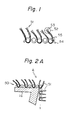
- Figure 1 shows a state of cut piles after having been dyed.
- the cut piles (51) projecting from a ground (54) are tilted over randomly and filaments (53) composing the cut piles are crossing each other.
- Deformation of each cut pile (51) occurs mainly in foot portions (55), while free portion (52) thereof being kept straight.
- the pile fabric to be finished is brought into contact with a heater such that the back surface of the fabric, namely the side opposite to the pile side faces the heated surface of the heater.
- a heater such that the back surface of the fabric, namely the side opposite to the pile side faces the heated surface of the heater.
- fluid having a temperature not higher than that of the heater is ejected from a nozzle to the surface of the fabric in the desired direction of standing of the cut piles.
- This fluid separates individually filaments comprising the cut piles as well as straightening and setting upright the cut piles.
- Air especially normal temperature air
- Various types of ejection are available, depending upon conditions of the pile fabric such as structure, density, pile length, and specific weight. Among them, two are preferable: a first type wherein the fluid is ejected directly to the pile side surface, immediately after heating the foot portion of the cut piles, from a nozzle disposed above a path of the fabric, and a second type wherein the fluid is ejected to the back surface and passes through it to the pile side surface, immediately after heating.
- the first type is preferably utilized for finishing pile fabrics provided with rather shorter cut piles, while the second type is suitable for longer cut piles.
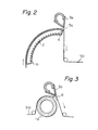
- Figures 2 and 3 show the devices utilized for the first type of ejection.
- an arcuate heater (la) having a little wider width than that of the fabric and having built therein heating wires (2) is disposed along a path of the pile fabric (50) with its convex heated surface in face to face contact with the back surface of the fabric.
- a nozzle (3a) for ejecting a cooling fluid also has a little wider width than that of the fabric and is disposed just above the rear end (4) of the heater (la) to face the pile side surface of the fabric (50).
- An outlet (5a) of the nozzle (3a) is inclined to the running direction of the fabric so as to make the cut piles stand upright.
- a roll heater (lb) which may be rotatable, is provided instead of the arcuate heater (la), and a nozzle (3b) is disposed instead of the nozzle (3a) just above a guide bar (6) located behind the heater (lb).
- An outlet (5b) of the nozzle (3b) is also inclined to the running direction of the fabric (50) as in Fig. 2.
- the running direction of the fabric be turned acutely just behind the heater (la), (lb). The reasons why the above-mentioned turning of the direction is desirable will be apparent later.
- the pile fabric (50) requiring finishing after dyeing is supplied to the heater (la) or (lb).
- the back surface of the fabric comes into face to face contact with the heated surface of the heater (la) or (lb).
- the heat from the back surface raises the temperature of the foot portion of the cut pile (51) (Fig. 1) to the degree necessary to plasticize the material composing the cut pile.
- the free end portion of the cut pile is hardly heated at all because of the material's poor heat conductivity. Since the fabric (50), as stated before, turns acutely in its running direction just behind the heater (la) or (lb), the individual cut piles (51) tend to stand upright at the turning point as shown in Fig. 2A. At the same time, the cooling fluid is ejected from the nozzle (3a) or (3b) to the foot portion along the direction shown by the arrow (A). This sets the cut piles (51) upright.
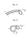
- FIGs 4 and 5 show the devices utilized for the second type of ejection.
- Heaters (lc) and (ld) correspond to heaters (la) and (lb), respectively, and are arranged in the same manner as shown in Fig. 2 and 3 respectively.
- Nozzles (3c) and (3d) correspond to nozzles (3a) and (3b), respectively, and are located at the rear ends of the heaters (lc) and (ld), respectively, positioned with their outlets facing the back surface of the fabric.
- the fabric (50) to be finished is advanced to the heater (lc) or (ld) and heated in the same manner as described before.
- the cooling fluid is supplied from the nozzle (3c) or (3d) to the back surface and passes through it to the pile side surface.
- the cut piles (51) are therefore blown upright from the foot portion and are set as they are. Thus, it is not necessary to turn the fabric running direction at the rear end of the heater (lc) and (ld).
- the region of the heater contacting the back surface of the fabric be convex. If not, close contact between the back surface and heater cannot be obtained and the ejected fluid may enter therebetween, causing uneven heating to the fabric.
- Each of the devices shown from Fig. 2 to 5 may be utilized singlely or repeatedly, or may be combined each other.
- the invention is suitably applied to fabrics provided with cut piles of a length from 0.5 to 5 mm.
- cut piles of a length from 0.5 to 5 mm.
- dishevellment of the cut piles seldom occurs even in the wet heat process and so application of the invention is meaningless.
- longer than 5 mm it is difficult to straighten the dishevellment of the cut piles even with the invention, because the deformation of the cut piles may reach their free end portions.
- the heater temperature utilized for the invention differs in accordance with conditions of the fabrics to be finished, such as the kinds of fibers composing the cut piles and heat careers thereof. It is, however, essential that the temperature be high enough to substantially plasticize the foot portion of the cut pile. Therefore, the heater temperature must be higher than the second order transition temperature of the fiber composing the cut pile, and, preferably, should be higher than the maximum temperature, which the cut pile experienced during the preceding processes.
- Too low a heater temperature reduces the effectiveness of the fluid applied soon after. On the other hand, if the heater temperature is excessively higher than the second order transition temperature, the cut pile will deform to much, thereby stretching, crimping, or discoloring.
- a heating temperature from 150°C to 220°C is preferable for cut piles composed of polyester fibers, from 120°C to 170°C for polyamide fibers, from 110°C to 170°C for polyacrylic fibers, and from 150°C to 220°C for triacetate fibers.
- the fabric to be finished does not have to be in the dry condition and can be dried at the same time as the heating process.
- the nozzle is preferably provided with a slit-like outlet and is connected to a high pressure fluid source.
- the nozzle may have a fixed ejecting direction outlet.
- the ejecting direction be adjustable in accordance with the conditions of the fabric to be finished, such as the length of the cut pile, degree of dishevellment, and treating speed.
- the nozzle should be disposed close to said heater for rapid cooling of the fabric and for greater compactness.
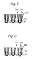
- Figure 7 shows the shape of the resultant cut pile (51a) achieved by means of the invention.
- Figure 8 shows cut pile (51b) obtained by a conventional finishing process in which a pile is first heated directly with hot air, then cooled with cooling air.
- filaments (53a) composing the cut pile are fully separated into individual fibers and stand upright from a ground (54).
- filaments (53b) are bent at the foot portion (55) and are crossed with each other as well as being deformed at the free end portions (52b) thereof.
- the former shows a much better evenness in appearance than the latter.
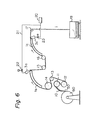
- Figure 6 shows a preferred arrangement according to the invention,.
- the arrangement is a combination of the devices shown in Figs. 2 and 4.
- the same reference numerals are used in Fig. 6 as in Figs. 2 and 4.
- the fabric (50), having been treated in dyeing process, is fed from a rolled package (60) to a spreading plate (10), utilized for removing wrinkles from the fabric, a feed roll (11), tension rolls (12), (13), a guide roll (14), and first arcuate heater (la).
- the fabric (50) is in contact with the first heater (la) such that the back surface of the fabric closely faces the heater surface.
- the foot portion of the cut pile which has been deformed by actions exerted during the dyeing process, are raised to a temperature to plasticize themselves.
- a nozzle (3a) disposed at the rear end of the heater (la) ejects cooling air of a lower temperature than that of the heater (la) to the pile side surface of the fabric (50) just at the turning point of the fabric running direction. The air is ejected in the direction along the fabric to make the cut pile stand upright.
- the filaments composing the cut pile are individually separated and straightened. At the same time, they are set in the shape as they are.
- the fabric (50) is then advanced via guide rolls (15), (16) to a second arcuate heater (lc) for heat treatment. Next, it is subjected to cooling air ejected from a nozzle (3c) disposed beneath the path of the fabric. The cooling air passes through the back surface to the pile side surface of the fabric and has the same effects on the cut pile as nozzle (3a).
- the air ejected from the nozzles (3a) and (3b) is supplied from a compressor (20) through a pipe (21) and control valves (22) and (23).
- Two kinds of gray fabrics having 3 mm and 5 mm length pile respectively were prepared with a 22G double raschel machine using polyester fiber filaments of 50 d/48 f as a ground component and polyacrylic fiber filaments of 100 d/120 f as a pile component.
- the fabrics were introduced into a jet dyeing machine. First, the polyester fiber part was carrier-dyed, then the polyacrylic part was dyed. After being squeezed with a mangle, they were padded with a liquid containing a cationic softener in a ratio of 10 g/i and were dried and tentered with a pintenter at a temperature of 120°C. Finally they were rolled up on a core.
- Cut piles on the resultant fabrics were randomly tilted and dishevelled.
- Both final fabrics obtained had upright standing cut piles with individual filaments separated fully from each other from the foot portion to the free end portion. As a whole, the fabrics had a soft touch and good velvet-like appearance both in evenness and in shade on the pile side surface.
- An gray fabric of 2 mm length pile was prepared with a pile loom using polyester fiber filaments of 50 d/12 f as a ground component and of 50 d/24 f as a pile component.
- the fabric was carrier-dyed with a jet dyeing machine, and was padded with a liquid containing antistatic agent in a ratio of 10 g/ll. After being dried and rolled up, the fabric, having dishevelled piles, was introduced into an arrangement, according to the invention, combining the devices shown in Figs. 3 and 5, in that order.
- the fabric was finished at a rate of 3 m/min under the following conditions:
- the resultant fabric had upright standing cut piles with individual filaments separated fully from each other from the foot portion to the free end portion.
- the fabric was a high class velvet-like fabric good in appearance due to apparent denseness of the cut piles.
- the same prefinishing fabric as stated in example 2 was prepared.
- the fabric was treated separately by two different conventional processes. One was the process usually utilized for finishing rayon velvet, which comprises repeated brushing and shearing. The other comprises ejection of hot air from the nozzle shown in Fig. 2 directly to the pile side surface of the fabric.
- the fabric according to the former process had tilted cut piles with deformed free end portions.
- the fabric according to the latter process had cut piles, with crossed individual filaments and deformed free end portions.
- An gray fabric of 3 mm length pile was prepared with a 22G double raschel machine using polyester fiber filaments of 50 d/48 f as a ground component and polyacrylic fiber filaments of 150 d/60 f as a pile component.
- the fabric was introduced into a jet dyeing machine. First, the polyester fiber part was carrier-dyed, then, the polyacrylic fiber part was dyed. After being aqueezed with a mangle, it was padded with liquid containing a cationic softener in a ratio of 10 g/t and was dried and tentered with a pintenter at a temperature of 120°C. Finally the fabric was rolled up on a core.
- Cut piles on the resulted fabric were randomly tilted all over the surface.
- the fabric was introduced into the device shown in Fig. 2 and was finished at a rate of 4 m/min under the following conditions:
- the same prefinished fabric as treated in example 3 was treated by a conventional process in which hot air was ejected from a nozzle directly to the pile side surface.
- the resultant fabric had cut piles with free end portions crimped by the heat from the hot air.
- the conventional process was very difficult to control in terms of operating conditions, such as ejecting pressure relating to the ejecting direction of the hot air, and was uneconomical due to its high heat-consumption.
- a gray fabric of 2 mm length pile was prepared with a velvet loom using triacetate fiber filaments 120 d/55 f as a pile component and polyester fiber filaments 50 d/48 f as a ground component.
- the fabric was dyed with a jet dyeing machine, padded with a liquid containing antistatic agent in a ratio of 10 g/i, and was dried with a pintenter.
- the fabric thus obtained had cut piles tilted down on the surface randomly. It was introduced into the arrangement shown in Fig. 6 and was finished at a rate of 4 m/min under the following conditions: As the resultant fabric was not satisfactory, the same finishing process was repeated once more whereby the desired product was obtained.
Landscapes
- Engineering & Computer Science (AREA)
- Textile Engineering (AREA)
- Treatment Of Fiber Materials (AREA)
Priority Applications (2)
| Application Number | Priority Date | Filing Date | Title |
|---|---|---|---|
| EP19820302214 EP0093207B1 (fr) | 1982-04-29 | 1982-04-29 | Procédé et appareil de finissage de tissus à poils |
| DE8282302214T DE3272284D1 (en) | 1982-04-29 | 1982-04-29 | Process and apparatus for finishing velvet-like fabrics |
Applications Claiming Priority (1)
| Application Number | Priority Date | Filing Date | Title |
|---|---|---|---|
| EP19820302214 EP0093207B1 (fr) | 1982-04-29 | 1982-04-29 | Procédé et appareil de finissage de tissus à poils |
Publications (2)
| Publication Number | Publication Date |
|---|---|
| EP0093207A1 true EP0093207A1 (fr) | 1983-11-09 |
| EP0093207B1 EP0093207B1 (fr) | 1986-07-30 |
Family
ID=8189652
Family Applications (1)
| Application Number | Title | Priority Date | Filing Date |
|---|---|---|---|
| EP19820302214 Expired EP0093207B1 (fr) | 1982-04-29 | 1982-04-29 | Procédé et appareil de finissage de tissus à poils |
Country Status (2)
| Country | Link |
|---|---|
| EP (1) | EP0093207B1 (fr) |
| DE (1) | DE3272284D1 (fr) |
Cited By (5)
| Publication number | Priority date | Publication date | Assignee | Title |
|---|---|---|---|---|
| EP1016750A3 (fr) * | 1998-12-30 | 2000-12-20 | Eduard Küsters Maschinenfabrik GmbH & Co. KG | Dispositif de redressement du poil d' un tissu |
| EP1775372A3 (fr) * | 2005-10-11 | 2007-12-19 | Kornbusch & Starting GmbH & Co. KG | Matériau textile avec un apprêt cationique et son utilisation. |
| EP1939344A1 (fr) * | 2006-12-16 | 2008-07-02 | Christy (UK) Limited | Appareil et procédé pour lever une pile de feuilles de bande de tissu |
| CN108350647A (zh) * | 2015-11-05 | 2018-07-31 | 帝斯曼知识产权资产管理有限公司 | 制造纺织产品的方法、该纺织产品的用途以及用于应用该方法的装置 |
| CN118029083A (zh) * | 2024-04-12 | 2024-05-14 | 晋江市豪伟织造有限公司 | 一种针织绒布定型工艺及其预缩定型装置 |
Citations (9)
| Publication number | Priority date | Publication date | Assignee | Title |
|---|---|---|---|---|
| FR826390A (fr) * | 1936-09-11 | 1938-03-30 | Procédé pour redresser et friser le poil des étoffes grattées et des tissus à poils en général | |
| FR2123981A5 (en) * | 1971-01-28 | 1972-09-15 | Bosch Balletbo Andres | Velour finishing treatment - for the production of synthetic fibre pile designs or patterns |
| JPS4920265A (fr) | 1972-06-15 | 1974-02-22 | ||
| GB1380071A (en) * | 1971-12-11 | 1975-01-08 | Lamberg Ind Res Ass | Method of processing pile fabrics |
| JPS5026676A (fr) | 1973-04-19 | 1975-03-19 | ||
| FR2299445A1 (fr) * | 1975-01-30 | 1976-08-27 | Craye & Fils | Procede de fabrication d'une peluche ou d'un velours double face et produits obtenus |
| FR2451415A1 (fr) * | 1979-03-15 | 1980-10-10 | Astin France Assist Tech Indle | Dispositif de chauffage pour un materiau souple en defilement |
| US4301577A (en) * | 1979-08-30 | 1981-11-24 | Bigelow-Sanford, Inc. | Process for treating tufted pile fabric |
| DE3031665A1 (de) * | 1980-08-22 | 1982-04-01 | Leo Sistig Kg, 4150 Krefeld | Vorrichtung zum rauhen bzw. aufrichten des pols textiler polware |
-
1982
- 1982-04-29 EP EP19820302214 patent/EP0093207B1/fr not_active Expired
- 1982-04-29 DE DE8282302214T patent/DE3272284D1/de not_active Expired
Patent Citations (9)
| Publication number | Priority date | Publication date | Assignee | Title |
|---|---|---|---|---|
| FR826390A (fr) * | 1936-09-11 | 1938-03-30 | Procédé pour redresser et friser le poil des étoffes grattées et des tissus à poils en général | |
| FR2123981A5 (en) * | 1971-01-28 | 1972-09-15 | Bosch Balletbo Andres | Velour finishing treatment - for the production of synthetic fibre pile designs or patterns |
| GB1380071A (en) * | 1971-12-11 | 1975-01-08 | Lamberg Ind Res Ass | Method of processing pile fabrics |
| JPS4920265A (fr) | 1972-06-15 | 1974-02-22 | ||
| JPS5026676A (fr) | 1973-04-19 | 1975-03-19 | ||
| FR2299445A1 (fr) * | 1975-01-30 | 1976-08-27 | Craye & Fils | Procede de fabrication d'une peluche ou d'un velours double face et produits obtenus |
| FR2451415A1 (fr) * | 1979-03-15 | 1980-10-10 | Astin France Assist Tech Indle | Dispositif de chauffage pour un materiau souple en defilement |
| US4301577A (en) * | 1979-08-30 | 1981-11-24 | Bigelow-Sanford, Inc. | Process for treating tufted pile fabric |
| DE3031665A1 (de) * | 1980-08-22 | 1982-04-01 | Leo Sistig Kg, 4150 Krefeld | Vorrichtung zum rauhen bzw. aufrichten des pols textiler polware |
Cited By (9)
| Publication number | Priority date | Publication date | Assignee | Title |
|---|---|---|---|---|
| EP1016750A3 (fr) * | 1998-12-30 | 2000-12-20 | Eduard Küsters Maschinenfabrik GmbH & Co. KG | Dispositif de redressement du poil d' un tissu |
| EP1775372A3 (fr) * | 2005-10-11 | 2007-12-19 | Kornbusch & Starting GmbH & Co. KG | Matériau textile avec un apprêt cationique et son utilisation. |
| US7919166B2 (en) | 2005-10-11 | 2011-04-05 | Kornbusch & Starting Gmbh & Co. Kg | Cationic finished textile material and its use |
| EP1939344A1 (fr) * | 2006-12-16 | 2008-07-02 | Christy (UK) Limited | Appareil et procédé pour lever une pile de feuilles de bande de tissu |
| CN108350647A (zh) * | 2015-11-05 | 2018-07-31 | 帝斯曼知识产权资产管理有限公司 | 制造纺织产品的方法、该纺织产品的用途以及用于应用该方法的装置 |
| JP2019502416A (ja) * | 2015-11-05 | 2019-01-31 | ディーエスエム アイピー アセッツ ビー.ブイ.Dsm Ip Assets B.V. | 繊維製品を製造するための方法、その使用、及びその方法を適用するための装置 |
| US10815614B2 (en) * | 2015-11-05 | 2020-10-27 | Dsm Ip Assets B.V. | Methods to manufacture a textile product |
| EP3371367B2 (fr) † | 2015-11-05 | 2023-03-29 | Covestro (Netherlands) B.V. | Procédé de fabrication d'un produit textile, son utilisation et dispositif permettant d'appliquer ce procédé |
| CN118029083A (zh) * | 2024-04-12 | 2024-05-14 | 晋江市豪伟织造有限公司 | 一种针织绒布定型工艺及其预缩定型装置 |
Also Published As
| Publication number | Publication date |
|---|---|
| EP0093207B1 (fr) | 1986-07-30 |
| DE3272284D1 (en) | 1986-09-04 |
Similar Documents
| Publication | Publication Date | Title |
|---|---|---|
| US6350504B1 (en) | Printed flocked pile fabric and method for making same | |
| US2815558A (en) | Pile fabrics and method of pile fabric treatment | |
| US4152886A (en) | Process for making yarn having alternate sections of greater and less bulk and product thereof | |
| US4670317A (en) | Production of materials having visual surface effects | |
| EP0093207B1 (fr) | Procédé et appareil de finissage de tissus à poils | |
| US4301577A (en) | Process for treating tufted pile fabric | |
| US3641635A (en) | Pile-fabric-finishing methods and apparatus | |
| CA1093802A (fr) | Fil mousse et methode de production | |
| US20060037154A1 (en) | Multi-colored pile fabric and process | |
| US4109356A (en) | Process for texturing synthetic fibrous material | |
| US3345718A (en) | Process and apparatus for texturizing textile material | |
| US6029328A (en) | Process and equipment for bulk-texturizing and simultaneous interlacing of thermoplastic yarns, using heating fluids | |
| EP0099639A1 (fr) | Installation et procédé pour l'amélioration de l'effet visuel de surface | |
| US3421193A (en) | Process for crimping multifilament yarn | |
| US3656214A (en) | Crimping apparatus for manufacturing a bulky yarn | |
| KR20020003200A (ko) | 제직 직물을 얻기 위한 방법 | |
| US2317375A (en) | Method of treating fabric, and fabric | |
| JPH0123577B2 (fr) | ||
| KR100282589B1 (ko) | 고신축성편지의 제조방법 | |
| JP4553933B2 (ja) | 加工糸の製造方法 | |
| JP4077178B2 (ja) | 加工糸及びその織編物 | |
| EP0909350A1 (fr) | Procede et appareil permettant d'eliminer les spirales dans des tissus tricotes | |
| US3780404A (en) | Process and apparatus for texturizing yarn | |
| JPS5851048B2 (ja) | 筋斑のない捲縮糸の製造方法 | |
| JPH0159367B2 (fr) |
Legal Events
| Date | Code | Title | Description |
|---|---|---|---|
| PUAI | Public reference made under article 153(3) epc to a published international application that has entered the european phase |
Free format text: ORIGINAL CODE: 0009012 |
|
| 17P | Request for examination filed |
Effective date: 19820614 |
|
| AK | Designated contracting states |
Designated state(s): BE DE FR GB IT NL |
|
| GRAA | (expected) grant |
Free format text: ORIGINAL CODE: 0009210 |
|
| AK | Designated contracting states |
Kind code of ref document: B1 Designated state(s): BE DE FR GB IT NL |
|
| REF | Corresponds to: |
Ref document number: 3272284 Country of ref document: DE Date of ref document: 19860904 |
|
| ET | Fr: translation filed | ||
| ITF | It: translation for a ep patent filed | ||
| PLBE | No opposition filed within time limit |
Free format text: ORIGINAL CODE: 0009261 |
|
| STAA | Information on the status of an ep patent application or granted ep patent |
Free format text: STATUS: NO OPPOSITION FILED WITHIN TIME LIMIT |
|
| 26N | No opposition filed | ||
| ITTA | It: last paid annual fee | ||
| PGFP | Annual fee paid to national office [announced via postgrant information from national office to epo] |
Ref country code: FR Payment date: 19950411 Year of fee payment: 14 |
|
| PGFP | Annual fee paid to national office [announced via postgrant information from national office to epo] |
Ref country code: GB Payment date: 19950418 Year of fee payment: 14 |
|
| PGFP | Annual fee paid to national office [announced via postgrant information from national office to epo] |
Ref country code: DE Payment date: 19950421 Year of fee payment: 14 |
|
| PGFP | Annual fee paid to national office [announced via postgrant information from national office to epo] |
Ref country code: NL Payment date: 19950430 Year of fee payment: 14 |
|
| PGFP | Annual fee paid to national office [announced via postgrant information from national office to epo] |
Ref country code: BE Payment date: 19950613 Year of fee payment: 14 |
|
| PG25 | Lapsed in a contracting state [announced via postgrant information from national office to epo] |
Ref country code: GB Effective date: 19960429 |
|
| PG25 | Lapsed in a contracting state [announced via postgrant information from national office to epo] |
Ref country code: BE Effective date: 19960430 |
|
| BERE | Be: lapsed |
Owner name: SAKAI SENI NAGOYA KOJO CO. LTD Effective date: 19960430 Owner name: MITSUBISHI RAYON CO. LTD. Effective date: 19960430 |
|
| PG25 | Lapsed in a contracting state [announced via postgrant information from national office to epo] |
Ref country code: NL Effective date: 19961101 |
|
| GBPC | Gb: european patent ceased through non-payment of renewal fee |
Effective date: 19960429 |
|
| PG25 | Lapsed in a contracting state [announced via postgrant information from national office to epo] |
Ref country code: FR Effective date: 19961227 |
|
| PG25 | Lapsed in a contracting state [announced via postgrant information from national office to epo] |
Ref country code: DE Effective date: 19970101 |
|
| NLV4 | Nl: lapsed or anulled due to non-payment of the annual fee |
Effective date: 19961101 |
|
| REG | Reference to a national code |
Ref country code: FR Ref legal event code: ST |